A Novel Tri-band Microstrip Antenna Design
with T-shaped Slots for C, X and Ku-band
Applications
Iti Sharma1, Amish K Jha2, Sumit Gupta3
M.Tech Scholar, Department of ECE, OCT College, Bhopal, M.P, India1
Assistant Professor, Department of ECE, OCT College, Bhopal, M.P, India2
HOD, Department of ECE, OCT College, Bhopal, M.P, India3
ABSTRACT: In this research, with the purpose of designing Multiband antenna and to enhanced the bandwidth and
gain of Microstrip antenna. The design is proposed in which Microstrip antenna patch is loading with two partially T-slot shaped, the shape of patch is rectangular and partial ground plane is used in design. Feeding is done by using Microstrip feed line. After designing antenna the simulations results shows the improvement multiband which has resonant frequency 4.4GHz, 8GHz, 9.6GHz, and 13GHz is achieved in low cost substrate FR4 Epoxy with highest bandwidth. The partially T-slot shaped patch antenna will operate at frequency above 9 GHz which will make it suitable for Ku band applications.
KEYWORDS:Microstrip antenna, partial ground plane, Tri-band, Microstrip feed line.
I. INTRODUCTION
II. RELATEDWORK
Microstrip antenna has many advantages like low profile to conformal easily, easy to fabricate in PCB, etc. With advantages it also have disadvantages like narrow bandwidth and low gain, to overcome these problems many researchers adopt many techniques due to these the problems can be resolve to a great extent.
Microstrip antenna invented by Bob Munson in 1972 (but earlier work by Dechamps goes back to 1953). This became popular after 1970. The revolution in large-scale integration and circuit miniaturization led to the development with this concept due to which wireless communication makes boom in market by its demand. These antennas widely used in mobile market and as it designed for above than 1GHz frequency this is used as microwave communication antenna. For high frequency this antenna will be best selection.
A Microstrip antenna also called patch antenna. A rectangular shaped Microstrip antenna consists of metal patch, ground plane, dielectric substrate, and feed line. Antenna patch, ground plane, feed line made up of high conductive material usually copper is selected. Substrate which has dielectric constant value between 1-9 can be selected by antenna engineer depends on its application.
Various Mathematical model and software were developed for simulation and modelling of this antenna which makes calculations very easy and less time consume for analysis. Many researchers publish there working antenna in many journals and conferences on this antenna which shows importance gained in research area. The analysis of this antenna can be done by Transmission line model and Cavity Model methods, these two methods or approaches are easy to implement in computer program within short computation time. According to P. Bhartia, 1980 with these two approaches the antenna characteristics are not very accurate which are limited to narrow band Microstrip antennas. But later a full wave analysis method, FDTD and MPIE have been proposed in which antenna characteristics is very accurate solved integral equations by Method of Moment (MoM). This MoM method applied for both single element and array of Microstrip antenna and also applied for single layer and multilayer configuration.
III.FORMULATION METHOD OF ANTENNA DESIGNING
In the process of design we needs to calculate some parameters for subtract and the ground and which will be easily calculated by formulas discussed below. To calculate width of the dielectric subtract
= 1
0 0 2
+ 1 (1)
Where is the resonance frequency, dielectric constant of the subtract & 0, 0 are the permeability and permittivity of free space respectively.
= 0 2
+ 1 (2)
Where 0 show the velocity of wave in free space.Now after calculating width of dielectric next is dielectric constant which we have to calculate and the formulas used to calculate dielectric constant is given by,
Here we considers effective length instead of original length because the Microstrip antenna looks longer as only because of fringing effect and the effective length of the antenna is differ by ∆ from the physical length. This extension in length is simply the ratio of width to the height and which is given by below formula
∆
=0.412(( . )( . )
. ) ( . ) (4)
Now the original length is given by
= −2 ∆ (5)
After calculating all these we have to calculate the dimension of the ground plane which will be varied for same antenna in some amount and this relation is given by
≥( )∗2 + (6)
= ≥
4 ∗2 + (7)
IV.ANTENNADESIGN
In this paper, antenna is designed by using ANSOFT HFSS (High Frequency Structural Simulator). A schematic diagram of the proposed frequency antenna is shown in Figure 1.The configuration comprises of Partial T shape patch antenna on a substrate of a thickness h and dielectric constant Ԑr.
Table 1: Showsthe dimension of various parameters of antenna.
V. EXPERIMENTAL RESULTS
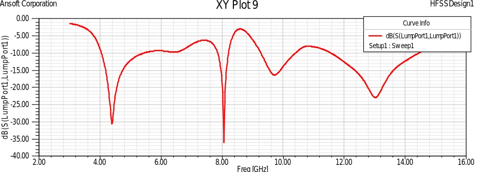
The results shown here are simulated on HFSS software. In HFSS, rectangular patch and partial ground plane are made up of PEC (Perfect Electrical Conductor) and air or vacuum can be used for the radiation box. Figure 2 shows the variation of return loss with frequency. Return loss is the loss of power in the signal returned/reflected by the discontinuity in a transmission line which occurs due to mismatch with terminating load. The gain of the antenna has been studied using a Microstrip patch antenna fabricated on the same substrate.
Fig 2: Return loss v/s frequency curve for varying length of ground plane
From the Figure 2, it is clear that optimum bandwidth is achieved when length of ground plane is 8mm and at resonating frequency 4.4GHz, 8GHz, 9.6GHz and 13GHz. Figure 3 shows VSWR v/s frequency curve at a particular width of ground plane. VSWR is simply the rate of prak amplitude of standing wave to the minimum amplitude of standing wave. VSWR below 2 is considered well for an antenna. For this design, VSWR is less than 2 from 4GHz-16GHz in figure 3.
2.00 4.00 6.00 8.00 10.00 12.00 14.00 16.00
Freq [GHz] -40.00 -35.00 -30.00 -25.00 -20.00 -15.00 -10.00 -5.00 0.00 d B (S (L u m p P o rt 1 ,L u m p P o rt 1 ))
Ansoft Corporation
XY Plot 9
HFSSDesign1Curve Info
dB(S(LumpPort1,LumpPort1)) Setup1 : Sw eep1
S.No Parameters Dimensions Material
1 Substrate Wsub=30 mm
Lsub=30 mm
Hsub= 1.6mm
FR4 EPOXY
2 Rectangular patch Lp= 11.64mm
Wp= 16mm
Copper
3 Ground Plane Wg= 30 mm
Lg= 16mm
Copper
4 Tap-Slot LHs= Varying
Ws= Varying
-
5 Feed line Wf= 3mm
Lf = 8 mm
Figure 3: Variation of VSWR v/s Frequency
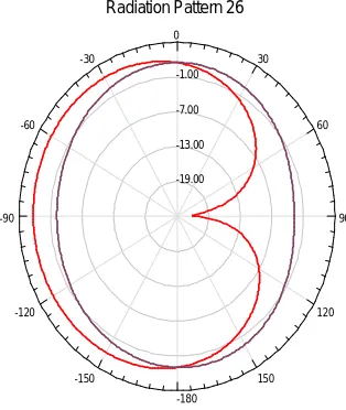
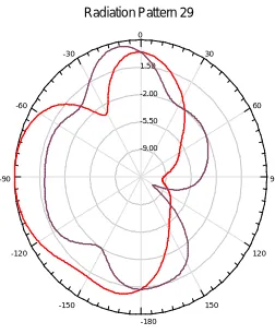
The E-plane is defined as the plane containing the electric field vector and the directions of maximum radiation while the H-plane is the plane containing the magnetic field vector and the direction of maximum radiation. The x-z plane elevation plane with some particular azimuth angle φ is the principle E-plane. While for the x-y plane azimuth plane with some particular elevation angle θ is principle H-plane. Figure 4,5 and Figure 6 shows 2D E-plane radiation pattern at frequency 4.4GHz, 7.2 GHz, 13GHz frequency.
Figure 4: 2D E-plane Radiation Pattern at 4.4 GHz
2.00 4.00 6.00 8.00 10.00 12.00 14.00 16.00
Freq [GHz] 0.00 5.00 10.00 15.00 20.00 25.00 d B (V S W R (L u m p P o rt 1 ))
Ansoft Corporation
XY Plot 8
HFSSDesign1Curve Info
dB(VSWR(LumpPort1)) Setup1 : Sw eep1
-19.00 -13.00 -7.00 -1.00 90 60 30 0 -30 -60 -90 -120 -150 -180 150 120
Ansoft Corporation Radiation Pattern 26 HFSSDesign1
Curve Info
dB(GainTotal) Setup2 : LastAdaptive Freq='4.4GHz' Phi='0deg'
Figure 5: 2D E-plane Radiation Pattern at 7.2 GHz
Figure 6: 2D E-plane Radiation Pattern at 13 GHz
Figure 7 and 8 shows 3D radiation pattern at 9GHz and 13GHz different frequencies within the band 8.1-13 GHz.
12.00 14.00 16.00 18.00
90 60 30 0 -30 -60
-90
-120 -150
-180 150
120
Ansoft Corporation Radiation Pattern 11 HFSSDesign1
Curve Info dB(rETotal) Setup1 : LastAdaptive Freq='7.2GHz' Phi='0deg'
dB(rETotal) Setup1 : LastAdaptive Freq='7.2GHz' Phi='90deg'
-9.00 -5.50 -2.00 1.50
90 60 30 0 -30 -60
-90
-120 -150
-180 150
120
Ansoft Corporation Radiation Pattern 29 HFSSDesign1
Curve Info dB(GainTotal) Setup4 : LastAdaptive Freq='13GHz' Phi='0deg'
Figure 8: 3D Radiation Pattern at 13 GHz
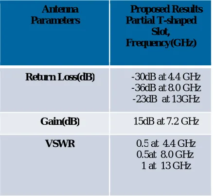
The partial slot antenna is suitable for data transmission at a particular range with less bandwidth which can be improved by making modifications in its length and shape through which the bandwidth can be vary. Table 2 shows some parameters of an antenna.
Antenna Parameters
Proposed Results Partial T-shaped
Slot, Frequency(GHz)
Return Loss(dB) -30dB at 4.4 GHz
-36dB at 8.0 GHz -23dB at 13GHz
Gain(dB) 15dB at 7.2 GHz
VSWR 0.5 at 4.4 GHz
0.5at 8.0 GHz 1 at 13 GHz
Table 2: Parameter of partial T Stair slot antenna
VI. CONCLUSION
television receiving only, the antenna can be used with possible degradation of the TV picture quality particularly during rain period.
REFERENCES
[1] Shuchismita Pani, Parameswar Banerjee, “Design and performance analysis of E shaped patch antenna with different feed point for
Ku-Band application.
[2] K.L. Wong and K.P. Yang ,”Compact dual frequency Microstrip antenna with a pair of bend slot,” Electronic letters, vol34,pp.225-226,
1988
[3] Prasad, P.C., Chattoraj, N., "Design of compact Ku band Microstrip antenna for satellite communication" Communications and Signal
Processing (ICCSP), 2013International Conference on, vol., no., pp.196, 200, 3-5 April.
[4] Mohamed A. Hassanien and Ehab K.I. Hamad, ”Compact Rectangular U-Shaped Slot Microstrip Patch Antenna for UWB
Applications”,2010 Middle East Conference on Antenna and Propagation, Cairo, Egypt
[5] Lida Kouhalvandi, Selcuk Paker , H. Bulent Yagci, “Ku - Band Slotted Rectangular Patch Array Antenna Design”, ©2015 IEEE
[6] Microstrip Patch Antenna Design for Ku Band Application RF circuit design: theory and applications / Reinhold Ludwig,
PavelBretchko, Prentice Hall, 2000, ISBN 0-13-095323-7.
[7] C. A. Balanis, Antenna Theory: Analysis and Design, John Wiley & Sons, 2012. Balanis, C. A., Antenna Theory, 3rd edition, Wiley
Interscience, 2005.
[8] Design of Microstrip Patch Antenna for Ku-Band Satellite Communication Applications, IJCCE, Vol.3, No.6, Nov2014.