Optimization of blank dimensions to reduce
springback in the flexforming process
Hariharasudhan Palaniswamy, Gracious Ngaile, Taylan Altan
∗ERC for Net Shape Manufacturing, The Ohio State University, 339 Baker Systems, 1971 Neil Ave., Columbus, OH 43210, USA
Abstract
In sheet metal forming operations, springback of the part during unloading largely determines whether the part conforms to the design dimensions and tolerances. Finite element simulations were performed in order to study the interrelationship of the blank dimensions and interface conditions on the springback for an axisymmetric conical part manufactured by flexforming. Sensitivity analysis done using the finite element method (FEM) demonstrated that the magnitude of springback and the overall dimensional quality are highly influenced by the initial dimensions of the blank. A conventional optimization method combined with FEM was used to obtain optimum blank dimensions that can reduce springback.
© 2003 Elsevier B.V. All rights reserved.
Keywords: Finite element; Flexforming; Springback; Optimization
1. Introduction
The sheet metal forming process involves a combination of elastic–plastic bending and stretch deformation of the workpiece. These deformations may lead to a large amount of springback of the formed part. It is desired to predict and reduce springback so that the final part dimensions can be controlled as much as possible. Ayres[1]suggested the use of a multiple step process to reduce springback in stamping operations. Liu[2]proposed to vary the binder forces during the forming process thereby providing tensile pre-loading to reduce the springback in the formed part. Techniques that are used in practice to reduce springback include stretch form-ing, arc bottoming and the pinching die technique. However, all these techniques transmit high tensile stresses to the walls of the deforming part thereby increasing the risk of failure by tearing, mainly in parts with complex geometries.
Several analytical methods have been proposed to predict the change in radius of curvature and included angle due to springback for plane-strain conditions and simple axisym-metric shapes. These methods are approximate and asso-ciate the source of springback to non-uniform distribution of strain and bending moment upon unloading.
The finite element method (FEM) is used widely to predict springback in research and industry. Currently, research is
∗Corresponding author.
E-mail address: [email protected] (T. Altan). URL: http://www.ercnsm.org.
focused on implementing hardening models in finite element formulations to accurately predict material behavior during unloading. Most FEM software packages use isotropic and kinematic hardening laws to simulate unloading behavior. However, none of them accurately predicts material behavior during unloading in a cyclic loading process. The material is treated as being much stiffer in isotropic hardening and very weak in kinematic hardening. Accurate prediction requires accounting for translation, rotation and expansion of yield surface in the finite element simulation. Jenn-Terng and Gary [3], Zhao and Lee[4], and Chun et al.[5]showed the use of a combined hardening model in the finite element simulation to accurately capture the Bauschinger effect exhibited by sheet metals during cyclic loading and unloading.
Inana and Chinghua[6]studied the influence of process variables of the methods used in practice to reduce spring-back by an optimization technique for U channel parts. Karafillis and Boyce [7] developed a deformation transfer function for changing the shape of the tool to compensate for springback in sheet metal forming using FEM.
The objective of this study was to estimate and reduce for springback of axisymmetric part manufactured by flforming process. The manufacturing sequence of the ex-ample part is shown in Fig. 1. The manufacturer selected the die and blank dimensions based on the experience and trial-and-error. However, the dimensions of the final part could not meet the design specifications due to its spring-back after forming. Thus, finite element analysis was used to predict springback in the existing manufacturing set-up.
Fig. 1. Process sequence for the example part.
Sensitivity analysis was also carried out to find the optimum process variables that can minimize the springback and ac-quire the reac-quired tolerance of the part.
2. Flexforming process
The flexforming process is similar to the forming opera-tions in stamping but is carried out in a fluid form cell. In the fluid form cell, a press ram with the oil and a flexible rubber diaphragm replaces the solid punch in a conventional press. The blank is kept on the rigid tool half, which defines the shape of the part. The trap ring is kept on the blank that acts as the blank holder (Fig. 2). The hydroforming unit moves downward while the die cavity, blank and the trap ring are stationary. The oil and the diaphragm wrap form and hold the blank over the die cavity, as shown inFig. 2.
Fig. 2. Flexforming process sequence: (i) initial set-up, (ii) closing the die cavity, (iii) forming the part and (iv) return.
Fig. 3. Finite element model of the flexforming process in DEFORM 2D.
3. Finite element analysis of flexforming process
3.1. Finite element model
FE simulations of the flexforming operation were con-ducted using an implicit finite element code DEFORM 2D. In the analysis the geometry was modeled over unit radians about the Z-axis because of the axisymmetric deformation mode,Fig. 3. An axisymmetric four-noded quadrilateral el-ement was used in the analysis. The sheet metal was uni-formly meshed with four elements in the thickness direction to capture the bending stress (Fig. 4). The trap ring was ne-glected due to difficulty in modeling the pressure boundary conditions while deformation of the sheet metal occurs. The presence of the trap ring only increases the shear stress due to friction and its influence is small. The process conditions used in simulations are shown inTable 1.
The friction coefficients (µ) of 0.05 and 0.10 as shown
inTable 1represent the minimum and maximum values of
the friction coefficient for the lubricant used in the actual process. The pressure was applied directly on the sheet metal as a linear function of time (Fig. 3). To predict springback, the contact boundary condition of the blank with the die was removed thereby allowing the metal to deform freely,
0.0 100.0 200.0 300.0 400.0 500.0 600.0 700.0 800.0 900.0 1000.0
0.0000 .200 0.4000 .600 0.8001 .000
True strain (mm/mm)
0.0 14.5 29.0 43.5 58.0 72.5 87.0 101.5 116.0 130.5 145.0
T
rue stress (Mpa)
T
rue stress (Mpa)
Process parameters used in simulation
Blank material AMS 5504
Young’s modulus, E (GPa) 210
Poisson’s ratio,ν 0.3
Flow stress curve Obtained from viscous bulge test (Fig. 4)
Hardening law Isotropic
Friction coefficient,µ 0.05–0.10 Maximum applied pressure (MPa) 22
reflecting unloading. To prevent rigid body movement, the blank was constrained at one node in the Z direction at the hole circumference.
3.2. Results and discussion
3.2.1. Forming
Flexforming of the investigated part is a combined stretch-ing and drawstretch-ing process. Durstretch-ing deformation, the material in the flange is pulled radially inwards. As the deformation proceeds, the area of contact of sheet metal with die cavity increases gradually, thereby increasing the resistance for the sheet metal to flow radially from the flange. Thus, after ini-tial drawing, the sheet metal in the cavity is stretched biaxi-ally to take the shape of the die. Due to biaxial stretching of the material, the hole at the center of blank expands and the material at the center moves radially outwards. This causes the strain to be maximum at the circumference of the hole over major part of deformation (Fig. 5). At the maximum pressure of 22 MPa the maximum strain is at the corner R2
due to stretching and bending (Figs. 6 and 7).
3.2.2. Springback
In the investigated part there were four corners R1–R4
over which the sheet metal is bent to take the die shape as shown in Fig. 7. Upon unloading, the metal springs back about these corners where the sheet metal was subjected to bending stress, and hoop stress. The amount of springback predicted by FE simulations is shown inTable 2.
Fig. 5. Effective strain distribution at a pressure of 3 MPa for friction coefficient (µ) of 0.05: (䊐) maximum effective strain and () minimum effective strain.
Fig. 6. Effective strain distribution at the maximum pressure of 22 MPa for friction coefficient (µ) of 0.05: (䊐) maximum effective strain and () minimum effective strain).
Fig. 7. Schematic representation of the formed part.
The springback was maximum at concave corners R1
and R3 compared to the convex corners R2 and R4. FE
simulation showed that the radial tensile stress at R2 and
R4 increases as the corners R1 and R3 are formed due to
the applied pressure. The tensile stresses due to stretching causes the neutral axis and the elastically deformed portion of the cross-section to shift towards the inner surface. When the tension is sufficiently high the neutral axis disappears and both inner surface and outer surface are deformed plastically. Thus the elastic recovery due to springback is relatively less at R2and R4as shown inTable 2.
Table 2
Formed part dimensions before and after springback for friction coefficient (µ) 0.05 (A, B, C, and D are the angles at corners R1, R2, R3 and R4, respectively, as shown inFig. 7)
Parameters Before springback
After springback
Change due to springback
A 46◦14 42◦55 −3◦19
B 46◦22 44◦54 −1◦28
C 145◦29 147◦10 1◦41
D 34◦32 34◦38 −0◦06
R1(mm) 13.43 14.68 1.25
R2(mm) 4.31 5.08 0.76
R3(mm) 31.77 33.80 2.03
Forming the part with tensile preload can reduce the amount of springback at corners R2 and R4. However, the
amount of tensile preload should be small enough not to initiate crack at the circumference of the inner hole diam-eter (Di) and localized thinning at the corners. It should
be noted that the maximum pressure of 22 MPa was not sufficient to form the corners R1 and R3. Forming the
cor-ners R1and R3, close to the die radius would significantly
increase the hoop stress and can reduce the springback. Po-tential ways to reduce the springback are: (a) changing the interface friction, (b) varying the blank dimensions and (c) increasing the maximum forming pressure. The influence of these variables on the springback was studied through sensitivity analysis.
4. Sensitivity analysis
A sensitivity analysis was carried out to find the influence of three parameters on the springback namely: (a) coefficient of friction (µ), (b) outer diameter of the blank, and (c) inner diameter of the blank. The springback was defined as the sum of the nodal displacement in the final part geometry (in the Z and R directions,Fig. 3) before and after springback divided by the total number of nodes (Eq. (1)):
Springback value= 1
N
N
i=1
(ri−ri)2+(zi−zi)2 (1)
where N is the total number of nodes in the finite element model, ri the R coordinate of the node before springback,
zi the Z coordinate of the node before springback, ri the R coordinate of the node after springback, andzi the Z coor-dinate of the node after springback
4.1. Influence of friction on springback
Finite element simulations of the forming process were conducted to study the influence of interface conditions on springback. In the simulations, the Coulomb friction coeffi-cient between the blank and die was varied fromµ=0.05 to 0.15, keeping the inner blank diameter (Di) and outer blank
diameter (Di) constant at 76.4 and 500.38 mm, respectively.
The maximum forming pressure of 22 MPa was used. FE results on the influence of friction are shown in Fig. 8. A very small increase in springback with increase in interface friction is observed, implying that friction has a negligible effect on springback for this part.
4.2. Influence of inner blank diameter on springback
Finite element simulations of the forming process were conducted to study the influence of inner hole diameter on springback. In the simulations, the inner blank diameter (Di)
was varied from 0 to 100 mm, keeping constant blank outer diameter (Do) of 500.38 mm, Coulomb friction coefficient
0.00 0.10 0.20 0.30 0.40 0.50 0.60
0 0.05 0.1 0.15 0.2
Coulomb friction coefficient
Springback value (mm)
Fig. 8. Sensitivity of springback to interface friction.
0.00 0.20 0.40 0.60 0.80 1.00 1.20 1.40 1.60 1.80
0 25 50 75 100 125
Blank inner hole diameter Di (mm)
Springback value (mm)
Fig. 9. Sensitivity of springback to hole diameter of the blank.
of 0.05, and the maximum forming pressure of 22 MPa. The springback for three inner blank diameters as predicted by FEM is shown inFig. 9. A small increase in springback for the blank without a hole compared to the blank with a hole diameter (Di) of 76.4 mm was observed. This may be due to
low strains in the flange region for the blank without a hole
(Figs. 10 and 11). Large springback was observed for the
blank with a hole diameter (Di) of 107.6 mm compared to
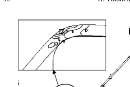
Fig. 11. Effective strain distribution of the formed part with hole diam-eter (Di) of 76.2 mm: (䊐) maximum effective strain and () minimum effective strain.
the blank with a hole diameter (Di) of 76.4 mm. This is due
to low strains at corner R2 for large blank hole diameters
(Figs. 11 and 12).
The trend predicted by FEM for outer diameter (Do) of
500.38 mm will not be the same for all blank outer diameters as the increase or decrease in outer diameter changes the restraining force acting on the blank during the forming. However, an optimum inner hole diameter (Di) is necessary
that can increase the strains in the flange as well as the corners R1–R4to reduce the springback.
4.3. Influence of outer blank diameter on springback
Finite element simulations of the forming process were conducted to study the influence of outer diameter on spring-back. In the simulations, the outer blank diameter (Do) was
varied from 400 to 560 mm. The inner blank diameter (Di)
of 76.4 mm, Coulomb friction coefficient of 0.05, and the maximum forming pressure of 22 MPa were kept constant.
Fig. 13shows that the springback increases with
increas-ing outer blank diameter (Do). Large outer blank diameters
restrain the material flow into the die cavity. Thus, formed corner radii R3and R1are large for large outer blank
diam-Fig. 12. Effective strain distribution of the formed part with hole diameter (Di) of 107.6 mm: (䊐) maximum effective strain and () minimum effective strain.
0.00 0.10 0.20 0.30 0.40 0.50 0.60
350 400 450 500 550 600
Outer blank diameter Do (mm)
Springback value (mm)
Fig. 13. Sensitivity of springback to outer diameter of the blank.
Fig. 14. Effective strain distribution of the formed part with outer blank diameter (Do) of 560 mm: (䊐) maximum effective strain and () mini-mum effective strain.
eter, which results in increased springback (Fig. 14). Also, the low strain in the flange due to less draw-in increases the springback for large blank diameters. For blank outer diam-eter (Do) of 400 mm, the entire flange is drawn into the die
cavity resulting in large strains in the flange and thereby re-ducing springback (Fig. 15). However, the chance of wrin-kling is quite high when the entire flange is drawn into the die cavity. The trend predicted for springback by varying the outer blank diameter (Do) may not be the same for all
hole diameters (Di) as the amount of material draw-in from
the flange during the process is also influenced by both the
blank hole diameter and the blank outer diameter. In the next section, optimum blank dimensions will be determined by combination of FEM and optimization technique.
5. Process optimization
5.1. Problem definition
Sensitivity analysis indicated that an optimum combina-tion of the hole diameter of the blank and outer diameter of the blank could reduce the springback. Therefore, an opti-mization problem was formulated to reduce springback as follows:
Minimizef(xi), i=1 ton, Subject togj(xi)≤0 or j=1 tom
where f(xi) is the objective or cost function that is to be minimized, xi,i=1 to n are the design variables that are to be optimized, gj(xi),j =1 to m are the constraints of the design problem and the design variables.
In this problem, the objective function f(xi) is the spring-back value given inEq. (1). Maximum wall thinning of 20% was used as constraint.
The design variables for the problem were: (i) blank hole diameter, Di; and (ii) outer blank diameter, Do.
The constraints on the design variable were: (1) 200 mm≥Di≥0 mm; and (2) 622.3 mm≥Do≥381 mm.
The maximum hole diameter (Di) is restricted by the size
of the trimmed diameter in the final part geometry. The dimensions of the press and the die restrict the dimension of outer blank diameter (Do).
5.2. Methodology
In this optimization problem, the objective function (springback value) and the constraint (thinning) are not explicit functions of design variables. They are the systems response and are evaluated for given design variable us-ing FEM. Solution to optimization problem involves two stages: (a) determination of the search direction, and (b) magnitude of change in design variable (α) along the search direction. The search direction for this problem was evalu-ated using conjugate gradient method. The gradients of the objective function and the constraints required to evaluate the search direction are obtained by the forward difference method [8]. The golden section method [8] was used for the one-dimensional search to find the magnitude of change in the design variable (α) along the search direction. Con-straints on the design variables were used in finding the initial limits for finding αalong the search direction. The flow chart shown inFig. 16describes the algorithm used to obtain optimum design variables that minimizes springback using FEM.
The one-dimensional search along the direction was ter-minated when the interval of uncertainty was reduced to
Fig. 16. Flow chart for the optimization method used to reduce the springback.
1 mm for both the design variables. The objective function is optimized when the dot product magnitude of the cur-rent iteration gradient vector and previous iteration direction vector is approximately equal to zero[8].
5.3. Results
In the combined optimization and FEM technique, the initial guess for the design variables blank hole diameter (Di) and outer blank diameter (Do) were 76.4 and 500 mm,
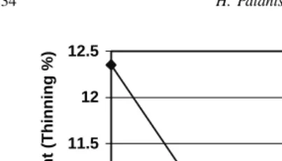
respectively. The evolution of the objective function and the thickness constraint during the optimization are shown in
Figs. 17 and 18, respectively. The objective function and the
0.00 0.05 0.10 0.15 0.20 0.25 0.30 0.35 0.40 0.45 0.50
0 1 2 3
Iteration No
Objective function (Spring
back Value) mm
10.5 11 11.5 12 12.5
0 1 2 3
Iteration No
Constraint (Thinning %)
Fig. 18. Evolution of the thickness constraint (% thinning).
thinning decreased with the change in the design variable during optimization. The percentage thinning was reduced from 12.4 to 10.6 indicating better uniform thickness in the formed part for the optimum blank dimensions compared to initial blank dimensions used in the optimization. During the optimization, the springback value has decreased from 0.45 to 0.28 mm indicating a reduction of 40% for the optimum blank dimensions compared to blank dimensions chosen by manufacturer based on experience. The local optimum inner hole diameter (Di) and outer blank diameter (Do) obtained
were 86.88 and 468.88 mm, respectively.
6. Conclusions and future work
Finite element analysis has been used to simulate a flex-forming operation and to predict the springback in the man-ufacturing of a cone shaped part. Sensitivity analysis on the influence of interface friction and blank dimensions on springback were carried out. Based on the results of the sen-sitivity analysis, an optimization problem was formulated to find the optimum blank dimensions that minimize the springback. The major conclusions drawn from this study are as follows:
1. Interface friction was found to have negligible effect on springback for flexforming process of the conical part considered in this study.
2. Inner hole diameter (Di) and the outer blank diameter
(Do) significantly influence the springback of the formed
part.
3. Optimization techniques combined with FEM can be ef-fectively used to optimize blank dimensions to minimize springback.
4. A local minimum in springback was obtained for the blank hole inner diameter (Di) of 86.88 mm and blank
outer diameter (Do) of 468.88 mm.
5. The optimum blank dimensions obtained by combined FEM and optimization reduced the springback by 40% compared to the blank dimensions chosen by the manu-facturer based on experience.
Future work will be conducted to compensate for spring-back in the die design using FE simulations.
Acknowledgements
Authors wish to acknowledge Pratt and Whitney Canada Corporation for partially funding this project.
References
[1] R.A. Ayres, A process to reduce sidewall curl springback in high strength steel rails, J. Appl. Metalwork. 3 (1984) 127.
[2] Y.C. Liu, The effect of restraining force on shape deviations in flanged channels, Trans. ASME, J. Eng. Mater. Technol. 110 (1988) 389. [3] G. Jenn-Terng, L.K. Gary, A new model for springback prediction
in which the Bauschinger effect is considered, Int. J. Mech. Sci. 43 (2001) 1813–1832.
[4] K.M. Zhao, J.K. Lee, Finite element analysis of the three-point bending of sheet metals, J. Mater. Process. Technol. 122 (2002) 6–11. [5] B.K. Chun, J.T. Jinn, J.K. Lee, Modeling the Bauschinger effect for
sheet metals. Part I. Theory, Int. J. Plasticity 18 (2002) 571–595. [6] C. Inana, H. Chinghua, Finite element analysis and optimization of
springback reduction, Int. J. Mach. Tools Manuf. 39 (1999) 517–536. [7] A.P. Karafillis, M.C. Boyce, Tooling and binder design for sheet metal forming process compensating springback error, Int. J. Mach. Tools Manuf. 36 (4) (1995) 503–526.