Plastic Separation Module for Municipal Solid
Waste
Gopinath E1, Suresh Kumar C2, Surya S3, Tamilselvan K4, Vijayasaravanan M5.
Department of Mechatronics Engineering, Maharaja Engineering College, Avinashi, Coimbatore, India
ABSTRACT: Plastic separation from municipal waste technology is a very difficult to handle. Only possible way is to destroy the plastics, they will burn or dump in ground. As the population of a country increases, the waste produced by them also increases tremendously. There are lot of methods for disposing the wastes such as landfills, incineration, etc. Machines which assist these methods are readily available in the market. The major problem with these types of machines is that they need a lot of space and also cost of the machine is high. This technology requires low cost and occupies a very less space. Simple components and mechanisms are used in this fabrication and an efficient waste separating machine is built.
I. INTRODUCTION
Plastic pollution involves the accumulation of plastic products in the environment that adversely affects wildlife, wildlife habitat or humans. Plastics that act as pollutants are categorized into micro, macro debris based on size. The prominence of plastic pollution is correlated with plastics being inexpensive and durable, which lends to high levels of plastic used by humans. However, it is slow to degrade. Plastic pollution can unfavorably affect lands, waterways and oceans. Living organisms, particularly marine animals can also be affected through entanglement, direct ingestion of plastic waste or through exposure to chemicals within plastics that cause interruptions in biological functions. Humans are also affected by plastic pollution, such as through the disruption of the thyroid hormone axis or hormone levels. Burning of plastic in the open air, leads to environmental pollution due to the release of poisonous chemicals.
Biswajit Ruj et al (2015) Separation of plastic from various types of waste streams represents one of major problematic process in energy recovery through different thermochemical processes. The sorting of plastics is a very essential step in different waste management technique. Manual sorting is suitable when plastic component are present in large amount but it is a labor intensive process[1].
A.Ahsan et al (2014) This study addresses the role of the city authority to meet the demand of the city dwellers in solving this emerging socio environmental issue and the initiatives taken by some nongovernmental organizations and community based organizations. The problems and constraints of the solid wastes management system are also
identified to find a sustainable management concept for the urban are as of Bangladesh[2].
Sesha Sai Ratnamala Bommareddy et al (2017) The aim of that paper is to consider the new capital city of A.P “AMARAVATHI” as a case study which is going to handle a huge population in upcoming years. Municipal solid waste is the key alert which would be soon knocking the city with managing and handling issues[3].
Vipin Upadhyay et al (2012) Solid waste management is a worldwide phenomenon. Improper management of solid waste (SW) causes hazards to inhabitants. It is a big challenge all over the world for human beings. The problem of solid waste management (SWM) is also prevailing in the urban environment of MNIT Campus[4].
Economic Automated Waste Segregator (AWS) which is a cheap and easy to use solution for a segregation system at households, so that it can be sent directly for processing[5].
II. MATERIALS AND EQUIPMENTS
The major parts that are effectively employed in the waste separating machine using belt conveyor drum are described below:
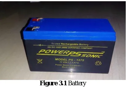
3.1 BATTERY
An electric battery is a device consisting of one or more electrochemical cells with external connections provided to power electrical devices such as flashlights, smartphones, and electric cars. When a battery is supplying electric power, its positive terminal is the cathode and its negative terminal is the anode. The terminal marked negative is the source of electrons that when connected to an external circuit will flow and deliver energy to an external device. This battery gives 12V and 7.5Amps power supply to the module. Figure 3.1 shows battery.
Figure 3.1 Battery
3.2 BEARING
Bearings are used for reducing the frictional force while the rotating motion. The bearings are pressed smoothly to fit into the shafts because if hammered the bearing may develop cracks.
Figure 3.2 Ball Bearing
3.3 SHAFT
Most shafts are made from steel, either low- or medium-carbon. However, high quality alloy steel, usually heat treated, may be chosen for critical applications. Other metals, e.g. brass, stainless steel or aluminium, may be used where corrosion is a problem or lightness is required.
3.4 MOTOR
An electric motor is a machine which converts electrical energy to mechanical energy. Its action is based on the principle that when a current-carrying conductor is placed in a magnetic field, it experiences a magnetic force whose direction is given by Fleming’s left hand rule.
Figure 3.3 DC Wiper Motor
Figure 3.3 shows the DC wiper motor. The very basic construction of a DC motor contains a current carrying armature which is connected to the supply end through commutator segments and brushes and placed within the north, south poles of a permanent or an electro magnet. Now to go into the details of the operating principle of DC motor its important that we have a clear understanding of Fleming’s left hand rule to determine the direction of force acting and the armature conductors of DC motor.
3.5 FRAME
This is made of mild steel material. The whole parts are mounted on this frame structure with the suitable arrangement. Boring of bearing sizes and open bores done in one setting so as to align the bearings properly while assembling. Provisions are made to cover the bearings with grease.
3.6 RACK AND PINION
Figure 3.4 Rack And Pinion
gears which convert rotational motion into linear motion. A circular gear called "the pinion" engages teeth on a linear "gear" bar called "the rack"; rotational motion applied to the pinion causes the rack to move relative to the pinion, thereby translating the rotational motion of the pinion into linear motion.
Rack and pinion combinations are often used as part of a simple linear actuator, where the rotation of a shaft powered by hand or by a motor is converted to linear motion.
3.7 CONVEYOR SETUP
A conveyor system is a common piece of mechanical handling equipment that moves materials from one location to another. Conveyors are especially useful in applications involving the transportation of heavy or bulky materials. Many kinds of conveying systems are available, and are used according to the various needs of different industries. There are chain conveyors (floor and overhead) as well. Chain conveyors consist of enclosed tracks, I- Beam, towline, power & free, and hand pushed trolleys. We use rubber material for conveyor.
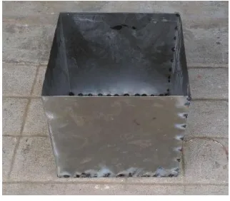
3.8 SHEET METAL
Sheet metal is metal formed by an industrial process into thin, flat pieces. It is one of the fundamental forms used in metalworking and it can be cut and bent into a variety of shapes. Countless everyday objects are fabricated from sheet metal. Thicknesses can vary significantly; extremely thin thicknesses are considered foil or leaf, and pieces thicker than 6 mm (0.25 in) are considered plate. Sheet metal is available in flat pieces or coiled strips. The coils are formed by running a continuous sheet of metal through a roll slitter.
Figure 3.5 Water Tank
We use sheet metal for making the water tank. The sheet metal has been cut by the cutter for required dimensions and it has been made as the tank by bending and welding process. Figure 3.5 shows water tank.
3.9 BELT AND PULLEY
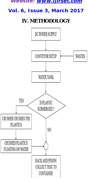
IV. METHODOLOGY
Figure 4.1 Block Diagram
Figure 4.1 shows the block diagram of the plastic separation module. The experimental setup of our project consists of a roller on which the conveyor rests. Near to the conveyor a container in which the crusher is provided. This crusher is used to separate the wastes easily. The motion to the crusher is delivered with the help of the DC motor. The conveyor is operated by using the DC motor and the spur gears. Another motor is used to operate the rack and pinion arrangement which separate the wastes that are crushed.
The end of the rack is attached with a block which moves along with the rack and pinion assembly. The power to all the motors is supplied with the help of the lead acid battery. The wastes irrespective of their type are fed to the conveyor manually. The wastes from the conveyor are automatically fed to the crushing container. The crusher which is operated by a motor crushes the wastes and reduces its sizes. That is the larger pieces of the wastes are broken down into smaller granules.
4.2 CALCULATION
For proper meshing of gears, the gear would be meshed must have more or less same pitch value.
Where,
4.2.1 Pitch Calculation For Pinion Pitch Diameter (D) = 4 cm Number of Teeth (T) = 25 P = 4
25
P = 3.632 cm
Rack :
Number of teeth = 74
Rack length = 38cm Addendum = 0.1cm Dedendum = 0.05cm
4.2.2 Water Tank Details
Length = 25 cm Breadth = 25 cm
Height = 25 cm
Volume = a3
= 253 = 15.625 cm3
Sheet thickness = 0.1 cm
4.2.3 Specifications of Conveyor Belt Material = Rubber Belt Length = 124 cm Width = 10 cm Roller Diameter = 4 cm Roller Length = 13 cm Shaft Length = 25 cm Shaft Diameter = 1.3 cm
4.2.4 Specifications of Crusher Diameter = 4 cm Length = 18.5 cm Shaft Diameter = 1.3 cm Shaft Length = 25 cm Crusher Blade Details:
4.2.5 Specifications of Collector Box Collector Box Length (l) = 24 cm Breadth (b) = 16 cm Height (h) = 6 cm
Volume = l X b X h
= 24 X 16 X 6
=2,304 cm3
4.2.6 Specifications of Belt
Belt size = A20
Type = V-belt
4.2.7 Specifications of Battery
Voltage = 12V Amphere = 7.5Amp
4.2.8 Specifications of Gear Motor
Revolution per minute = 30rpm
Voltage = 12V
4.2.9 Specifications of conveyor Motor
Revolution per minute = 100rpm
Voltage = 12V
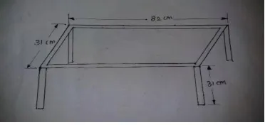
4.3 FRAME DIMENSIONS
Figure 4.2 Frame Dimensions Figure 4.2 shows frame dimensions.
Width of the frame = 31cm Thickness of the frame = 0.2cm
4.4 ADVANTAGES
Simple in construction.
Easy to fabricate and highly reliable.
The components used are easily available.
The wastes can be separated within shorter period of time.
No need of skilled operators to operate this system.
Repairing and replacing of the parts is not a difficult task.
Efficient method of waste separating process.
4.5 APPLICATIONS
These types of waste separating
machines using belt conveyor drum have a wide range of applications in the fields like,
Municipal corporations, Waste disposal industries, Waste recycling departments, All industries.
V. RESULT AND DISCUSSIONS
Existing MSW models that are successfully being implemented. • Door step Collection and transportation of the Waste generated • Waste minimization and promotion of waste for recycling
• Stakeholders engagement in the implementation • Processing, Treatment and Disposal of Waste
• State Level Institutional programs and arrangements.
VI. CONCLUSION
The proposed system is aimed towards the welfare infantry to minimize the causalities to a great extant. Municipal Solid Waste collection from the households at door step and transportation of MSW through trucks and mini vehicles which is collected by from door to door and from small bins on street. This collected municipal waste is transported for the disposal and treatment plants where a successful model idea is suggested which can give up good end results of complete treatment of solid waste by automated solid waste method where plastic is separated automatically and all the bio degradable material is formed as a slurry and released through the equipment.
REFERENCES
1. Abbasi M, Salarirad MM, Ghasemi I.,“Selective Separation of PVC from PET/PVC Mixture Using Floatation by Tannic Acid Depressant”, Iranian Polymer Journal 19(7), 2010 pp: 483-89.
2. Hori K, Tsunekawa M, Ueda M, Hiroyoshi N, Ito M, Okada H., “Development of a New Gravity Separator for Plastics -a Hybrid-Jig”, Materials Transactions, 50, 2009 pp:2844 -47.
3. Houzeaux G, Samaniego C, Calmet H, Aubry R,Vázquez M, Rem P., “Simulation of Magnetic Fluid Applied to Plastic Sorting”. The Open Waste Management Journal, 3, 2010 pp: 127- 38.
Z.,“Identification and Classification of Plastic Resins using Near Infrared, Reflectance Spectroscopy”, International Journal of Mechanical and Industrial Engineering, 6,2012 pp: 213-20.
5. Pappa G, Boukouvalas C, Giannaris C, Ntaras N, Zografos V, Magoulas K,Lygeros A, Tassios D., “The selective dissolution/precipitation technique for polymer recycling: a pilot unit application”, Resources, Conservation and Recycling, 34, 2001 pp: 33 – 44.
6. Park CH, Park JK, Jeon HS, Chun BC,“Triboelectric series and charging properties of plastics using the designed vertical-reciprocation charger”, Journal of Electrostatics, 66, 2008 pp: 578–83.
7. Pascoe RD, O’Connell B., “Development of a method for . Dodbiba G, Fujita T., “Physical separation of PVC and PET using Separation in Science and flame treatment and flotation”,Engineering”, Progress in separatingplastic materials for recycling 13, 2004 pp: 165-182.3.
8. Dodbiba G, Shibayama A, Sadaki J,Fujita T., “Combination of Triboelectrostatic Separation and Air Tabling for Sorting Plastics from a Multi-Component Plastic Mixture”, Special Issue on New Systems and Processes in Recycling and High Performance Waste Treatments ,4412,2003 pp: 2427-35.
9. Edward A Bruno, “ Automated Sorting of Plastics for Recycling”, pp: 3-16.Minerals Engineering, 16, 2003 pp: 1205 -1512.
10. Saiter JM, Sreekumar PM., “Different ways for re-using polymer based wastes”, The examples of works done in European countries. Recent Developments in Polymer Recycling, 2011 pp: 261-91.
11. Sena D, Nardi G, Cenedese C., “The hydraulic separator Multidune: Preliminary tests on fluid-dynamic features and plastic separation feasibility”, Waste Management, 289, 2008 pp: 1560-71.
12. Shen Ha, Forssberg E, Pugh RJ., “Selective flotation separation of plastics by chemical conditioning with methyl cellulose”, Resources, Conservation and Recycling,35, 2002 pp: 229–41.
13. Teichmann D, Masood S, Iovenitti P, Sbarski I, Kosior E., “Development of High Performance Sorting Process for Recycling of Plastics”, pp:122-27.
14. Tilmatine A, Medles K, Younes M, Bendaoud A, Dascalescu L., “Roll-type versus Free-fall Electrostatic Separation of Tribocharged Plastic Particles”, Particles and Instruments, 2009 pp:1-4.
15. Trans Forum, “Transportation Technology R&D Center”,Agronne national laboratory, 04.