ISSN(Online): 2319-8753 ISSN (Print): 2347-6710
I
nternational
J
ournal of
I
nnovative
R
esearch in
S
cience,
E
ngineering and
T
echnology
(An ISO 3297: 2007 Certified Organization)
Website: www.ijirset.com Vol. 6, Issue 8, August 2017
Structural Analysis of Multilayer Pressure
Vessels for Different Shapes of Cross Sections
by Using FEM
G. Lakshmi Praveena 1, S. Eshwari 2, K.Kiran Kumar 3, Dr.M.V.Ramesh 4
P.G. Student, Department of Mechanical Engineering, SVEC Engineering College, Tadepalligudem, Andhra Pradesh, India1
P.G. Student, Department of Mechanical Engineering, SVEC Engineering College, Tadepalligudem, Andhra Pradesh, India2
Associate Professor, Department of Mechanical Engineering, SVEC Engineering College, Tadepalligudem, Andhra Pradesh, India3
Head of the Department, Department of Mechanical Engineering, SVEC Engineering College, Tadepalligudem, Andhra Pradesh, India4
ABSTRACT: Sandwich structures have been widely used in aerospace structures, ship building, infrastructure, etc. due to their light weight and high strength to weight ratio. Traditionally, light-weight core materials such as foam core, truss core, honeycomb core have been used in fabricating sandwich structures with limited success. The aim of this work is to evaluate the effect of core shape in sandwich panels. The different core shapes panels, namely Rectangular Core, Hollow Rectangular Core, Circular Core and elliptical core sandwich panels are taken into study and their mechanical behaviour is compare using simulations techniques. There are many applications based on sandwich structures, but in this project we have taken the pressure vessel as application. The core shape structures are placed in between the layers of the pressure vessel to improve the strength and to reduce the weight of the pressure vessel. To find out the best core shape sandwich structure we have used simulation techniques.
KEYWORDS:ANSYS, SOLID WORKS, Multi Layer Pressure Vessels. I. INTRODUCTION
A sandwich structure is a fabricated material that consists of two thin, stiff facing sheets joined to either side of a low density core material or structure. The separation of the facing by a light weight core acts to significantly increase the second moment of area (and hence the bending stiffness) of the material cross section with only a small increase in weight. The construction is often used in light weight applications such as aircraft, marine applications, wind turbine blades, industrial platform sand floors. The face sheets of sandwich panels provide structural stiffness and protect the core against damage and weathering. During loading, the face sheet stake compressive and tensile loads and core is subjected to shear loads between the faces, thus providing high bending stiffness. Sandwich structures are used in applications requiring high stiffness to weight ratios, since for a given weight, the sandwich structure has a much higher moment of inertia compared to solid.
ISSN(Online): 2319-8753 ISSN (Print): 2347-6710
I
nternational
J
ournal of
I
nnovative
R
esearch in
S
cience,
E
ngineering and
T
echnology
(An ISO 3297: 2007 Certified Organization)
Website: www.ijirset.com Vol. 6, Issue 8, August 2017
been the main motivations for this thesis Sandwich panels are popular in high performance applications where weight must be kept to a minimum for example aeronautical structures high speed marine craft and racing cars in the most weight critical applications composite materials are used for the skins cheaper alternatives such as aluminium alloy. steel or plywood are also commonly used Materials used for cores include polymers aluminium wood and composites To minimise weight these are used in the form of foams honeycombs or with a corrugated construction .As well as mechanical requirements core.
II. LITERATURE REVIEW
V.N. Scoping sky and A.B. Smetankin describes the structural model and stress analysis of nozzle connections in ellipsoidal heads subjected to external loadings. They used Timoshenko shell theory and the finite element method. The features of the structural model of ellipsoid-cylinder shell intersections, numerical procedure and SAIS special-purpose computer program were discussed. A parametric study of the effects of geometric parameters on the maximum effective stresses in the ellipsoid-cylinder intersections under loading was performed. The results of the stress analysis and parametric study of the nozzle connections are presented
Drazan,Pejo, Fra V.N. Scoping sky and A.B. Smetankin describes the structural model and stress analysis of nozzle connections in ellipsoidal heads subjected to external loadings. They used Timoshenko shell theory and the finite element method. The features of the structural model of ellipsoid-cylinder shell intersections, numerical procedure and SAIS special-purpose computer program were discussed. A parametric study of the effects of geometric parameters on the maximum effective stresses in the ellipsoid-cylinder intersections under loading was performed. The results of the stress analysis and parametric study of the nozzle connections are presented
Drazan,Pejo, Franjo and Darko (2010) considered influence of stresses resulting from weld misalignment in cylindrical shell circumferential weld joint on the shell integrity. The stresses estimated analytically by API recommended practice procedure and calculated numerically by using the finite element method
njo and Darko (2010) considered influence of stresses resulting from weld misalignment in cylindrical shell circumferential weld joint on the shell integrity. The stresses estimated analytically by API recommended practice procedure and calculated numerically by using the finite element method
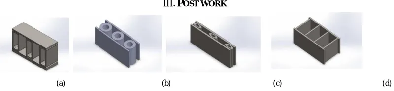
III.POST WORK
Fig. 2. Core Shape Structures (a) Hollow rectangular type of core structure (b) Hollow circle type of core structure (c) Hollow ellipse type core structure (d) Rectangle type core structure.
ISSN(Online): 2319-8753 ISSN (Print): 2347-6710
I
nternational
J
ournal of
I
nnovative
R
esearch in
S
cience,
E
ngineering and
T
echnology
(An ISO 3297: 2007 Certified Organization)
Website: www.ijirset.com Vol. 6, Issue 8, August 2017
Hollow Rectangular section : Rectangle section :
Area = A1-A2 Area = 70*10
= (70*30)-(60*20) = 700mm2 Area = 900mm2
Circular section : Hollow ellipse section :
= = = 20 Area = −
= = = 10 =
∗30∗12− ∗15∗6
Area = − Area = 848.23
= (20) − (10)
AREA =942.47
Upper plate and lower plate :
Upper plate Area A = 150*5 = 750
Lower plate Area A = 150*5 = 750
Calculation of weight of the whole bodies: Hollow rectangular structure: Materialconsidered is Mild steel W = volume*density*gravity
= 7.88 ⁄ Weight W = A*l*ρ*g
= v*ρ*g
= 0.9*0.05*788*9.81 = 347.86
w = + +
w = 1043.58gm
Weight of plate: Rectangular structure:
= 0.75*0.05*788*9.81 Weight of rectangular one = ∗ ∗ ∗
= 289.88 = 0.7*0.05*788*9.81
= + = 270.5598 = 579.771 = + + +
Total weight of structure W = w+ W = 1082.23gm
W =1043.58+579.771 Weight of the plate:- = 0.75∗0.05∗788∗9.81
W = 1.623kg = 289.88gm
= + = 573.771 Total weight of the structure body W = w+ W = 1082.23+579.771
ISSN(Online): 2319-8753 ISSN (Print): 2347-6710
I
nternational
J
ournal of
I
nnovative
R
esearch in
S
cience,
E
ngineering and
T
echnology
(An ISO 3297: 2007 Certified Organization)
Website: www.ijirset.com Vol. 6, Issue 8, August 2017
Hollow circular structure: Hollow ellipse structure:
Weight of the Hollow circular one = ∗ ∗ ∗ Weight of the Hollow ellipse structure one = 0.942*0.05*788*9.81 = ∗ ∗ ∗
= 364.27 = 0.848*0.05*788*9.81 w = + + = 327.85
w = 1092.8gm = + + , Total weight of the plates = + w = 983.55gm
= 579.771 Weight of the plates = +
Total Weight of the structural body = 579.771
W = + Total weight of the structure body W = +
= 1092.8+579.771 = 1.56kg
W = 1.67kg *Approximately Total Weight of the all core structure is 1.62kg
IV.EXPERIMENTAL RESULTS
Simulation of rectangle :
Mesh Information :
Resultant and Forces Reaction Forces :
Selecti on set
Uni
ts Sum X
Sum Y Sum Z
Resulta nt
Entire Model
N -0.01220 99
-0.002197 45
-149.9 66
149.96 6
Reaction Moments :
Selection set Units
Sum X
Sum Y
Sum Z
Resultant
Entire Model
N·m 0 0 0
Name Type
Min
Max
Stress1 VON: von Mises Stress
60.3632 N/m^2 Node: 5827
559536 N/m^2 Node: 2330
rect-Study 1-Stress-Stress1
Name
Type
Min
Max
Displace ment1
URES: Resultant Displacement
0 mm Node: 5049
0.000223408 mm
Node: 3637
ISSN(Online): 2319-8753 ISSN (Print): 2347-6710
I
nternational
J
ournal of
I
nnovative
R
esearch in
S
cience,
E
ngineering and
T
echnology
(An ISO 3297: 2007 Certified Organization)
Website: www.ijirset.com Vol. 6, Issue 8, August 2017
Name
Type
Min
Max
Strain1 ESTRN: Equivalent Strain
3.18091e-010 Element: 4499
1.75067e-006
Element: 402
rect-Study 1-Strain-Strain1
Similarly, by using ANSYS the stress, strain and displacement are found for Hollow Rectangle, Hollow Ellipse and Hollow Circle and the results are tabulated below:
Results obtained from the respective core shapes:
S NO Structure Strain Stress Displacement
(mm)
Factor of Safety
Weight (N)
1 Rectangle 1.75067 x 10⁻⁶ 559536 N/m
2
0.000223408 505.52 2.88387
2 Hollow Rectangle 8.7131 x 10⁻⁷ 246640 N/m
2
9.0047 x 10⁻⁵ 1146.85 2.88487
3 Hollow Ellipse 4.72003 x 10⁻⁶ 1.65431 x 10
6
N/m2
0.000521869 170.96 2.88487
4 Hollow Circle 3.33632 x 10⁻⁶ 1.038 x10⁶ N/m2 0.000383581 272.50 2.88487
Pressure Vessels
Pressure vessels are used to store and transmit liquids, vapour, and gases under pressure in general. The pressure of these finds will exert pressure equally in all direction on the walls and ends of pressure vessels .Because of the internal loading, stresses are including on certain section s of the cylinders (pressure vessels) wall. The pressure vessels (cylindrical or spherical) are generally used in engineering to store fluid under pressure .Major uses of pressure vessels are as follows
Pressure vessels are used in steam boilers.
Pressure vessels are also used in storage of chemical in chemical plants. Used in storage of petroleum products(petrol, diesel etc.).
It is also used in engine cylinders.
Model of Pressure Vessels with various core shapes:
ISSN(Online): 2319-8753 ISSN (Print): 2347-6710
I
nternational
J
ournal of
I
nnovative
R
esearch in
S
cience,
E
ngineering and
T
echnology
(An ISO 3297: 2007 Certified Organization)
Website: www.ijirset.com Vol. 6, Issue 8, August 2017
PRESSURE VESSEL CALCULATIONS : Calculations on pressure vessels:
layers pressure vessel
Diameters of the 3layers pressure vessel 100,130,160,190(in mm) In pressure vessel majorly the failure occurs due to
circumferential stress ( )
Calculating the hoop stress on layer one:- For layer one the inner and outer diameters are 100mm and 130mm
= 100
= 130mm
=
2 = 50
=
2 = 65
Circumferential stress or hoop stress: = [ + 1] K=
=
= ∗ [ + 1]
= 43.47[2.69]
= 116.93 ⁄
Longitudinal stress :
=
−
= ∗
= 43.47 ⁄
Maximum principal stress :
[ ] ≤
K = = =1.3
=
= ( ) Internal pressure = 30 ⁄
30[ .
. ]≤ 260
116.95 ≤ 260
Maximum principal strain :
= +
= 0.3
> [ + 1
−1+ 1
[ −2
−1]] > 30[1.3 + 1
1.3 −1+
1 [1.3 −2
1.3 −1]]
260 ≤ 115.35
Maximum shear stress :
= [ + 1]
=
= ( . )( . )
= 73.47 ⁄
Layer two:-
Diameters: - =130mm =160mm
Radius: - = = 65mm
= = 80mm Hoop stress
= [ + 1]
= k
= ∗ [ + 1] = 58.27[2.51]
= 146.27 ⁄
Longitudinal stress :
=
−
= ∗
= 58.27 ⁄
Max principal stress :
[ ] ≤
K = = =1.23
=
= ( ) Internal pressure = 30 ⁄
30[ .. ]≤ 260
146.98 ≤ 260
Maximum principal strain :
= +
= 0.3
≥ [ + 1
−1+ 1
[ −2
−1]]
≥30[1.23 + 1
1.23 −1+
1
[1.23 −2
1.23 −1]]
260≥30[4.899−0.284]
260≥138.46 safe
Maximum shear stress:
= = [ + 1]
=
= ( . ) ( . ) = 88.49 ⁄
Layer three:-
Diameters: - =160mm =190mm
Radius: - = = 80mm
= = 95mm Hoop stress
= [ + 1]
= k
= ∗ [ + 1] = 73.14[2.41]
= 176.27 ⁄
Longitudinal stress:-
=
−
= ∗
= 73.14 ⁄
Maximum principal stress : [ ] ≤
K = = =1.1875
=
= ( ) Internal pressure = 30 ⁄
30[.
. ]≤ 260
176.28 ≤ 260
Maximum principal strain:
= +
= 0.
> [ + 1
−1
+1[ −2
−1]] > 30[1.1875 + 1
1.1875 −1+ 0.3[
1.1875 −2
1.1875 −1]]
260> 30[4.899−0.284]
260> 163.35
Maximum shear stress:
= = [ + 1]
=
= ( . ) ( . ) = 103.142 ⁄
Considering as a three layer in to single layer:-
single layer pressure vessel
Diameters: - =100mm
=190mm Radius: - = = 50mm
= = 95mm
Hoop stress
= [ + 1]
= k
ISSN(Online): 2319-8753 ISSN (Print): 2347-6710
I
nternational
J
ournal of
I
nnovative
R
esearch in
S
cience,
E
ngineering and
T
echnology
(An ISO 3297: 2007 Certified Organization)
Website: www.ijirset.com Vol. 6, Issue 8, August 2017
= 52.98 ⁄
Longitudinal stress
=
−
= ∗
= 11.49 ⁄
Maximum principal stress: [ ] ≤
K = = =1.9
=
= ( ) Internal pressure = 30 ⁄
30[ .
. ]≤ 260
52.98 ≤ 260
Maximum principal strain: = +
= 0.3
> [ + 1
−1+ 1
[ −2
−1]]
> 30[1.9 + 1
1.9 −1+ 0.3[
1.9 −2
1.9 −1]]
260> 30[1.766 + 0.3∗ .
. ] 260> 58.53 safe
Maximum shear stress:
= = [ + 1]
=
= ( . )( . )
= 41.49 ⁄
Circular core type pressure vessel :
Mesh Information :
Resultant Forces Reaction Forces
Selectio n set
Uni
ts Sum X
Sum Y Sum Z Resu
ltant Entire
Model
N -1.68723
0.129002 -4.28174 4.603 98
Reaction Moments
Selection
set Units
Sum X
Sum Y
Su m Z
Resul tant Entire
Model
N·m 0 0 0 0
Study Results :
Name Type Min Max
Stress1 VON: von Mises Stress
0 N/m^2 Node: 1
1.39552e+008 N/m^2 Node: 20097
Assem3-Study 1-Stress-Stress1
Name Type Min Max
Displacement1 URES: Resultant Displacement
0 mm Node: 1
0.0111916 mm Node: 19797
ISSN(Online): 2319-8753 ISSN (Print): 2347-6710
I
nternational
J
ournal of
I
nnovative
R
esearch in
S
cience,
E
ngineering and
T
echnology
(An ISO 3297: 2007 Certified Organization)
Website: www.ijirset.com Vol. 6, Issue 8, August 2017
Similarly, by using ANSYS the stress, strain and displacement are found for Hollow Rectangle Core Type Vessel, Hollow Ellipse Core Type Vessel and Hollow Circle Core Type Vessel and the results are tabulated below:
Results obtained from the respective core shapes:
S NO Material Structure Strain Displacement (mm)
Factor of Safety
Weigh t (Kg)
1 SS1035 Rectangle 0.00026 0.00692 2.68 6.13
2 SS1035 Hollow Ellipse 0.00047 0.01139 1.68 6.92
3 SS1035 Hollow circle 0.00037 0.011916 2.025 6.92
4 SS1035 Hollow Rectangle 0.000302 0.085 2.53 5.91
V. CONCLUSION
In this project the different core shaped structures, namely Rectangle Core, Hollow Rectangular Core, Hollow Circular Core and Hollow ellipse core sandwich panels are taken into study and their mechanical behavior is compared, For evaluating mechanical behavior of the core sandwich Structures, on the basis of simulations techniques. Compare to all stress values, The Hallow circular cross sections have less stress at same weight and same load. So, at this circular cross section is suitable for application for members subjected to compressive loads. For considering the multilayer sandwich pressure vessels subjected to same pressure at different cross sections, Stresses induced in this cross sections hallow rectangle type is compared to remaining. So, this cross section is suitable for pressure vessels. So by using this kind of cross sections the weight reduces and strength increases. Finally based on the results of the analysis, we observed that hollow rectangular shape has got the optimum values like factor of safety, weight, deformation, stress and strain values
REFERENCES
[1] Impact and Strength Analysis of All-Steel Sandwich Structures For Different Core Shapes (International Journal of Trends and Technology –Volume 32 Number 2-February 2016) Dr.A.Gopichand, B Mahesh Krishna, P S N Raju.
[2] Optimum Design of Three Layer Compound Cylinder(IOSR Journal of Mechanical and Civil Engineering Volume 11, Issue 3 (May-Jun 2014)Tappan Mujumdar ,Dulal Krishna, SusenjitSarkar.
Name Type Min Max
Strain1 ESTRN: Equivalent Strain
0
Element: 1
0.000374341 Element: 10089
ISSN(Online): 2319-8753 ISSN (Print): 2347-6710
I
nternational
J
ournal of
I
nnovative
R
esearch in
S
cience,
E
ngineering and
T
echnology
(An ISO 3297: 2007 Certified Organization)
Website: www.ijirset.com Vol. 6, Issue 8, August 2017
[3] Stress Analysis of Multilayer Pressure Vessel(International Journal of Engineering and Technical Research Volume 2, Issue 9, Sep 2014)Dr.D.V.Bhope, prof.S.D.khamankar.
[4] L Valdevit, JW Hutchinson, AG Evans (2004), "Structurallyoptimized sandwich panels with prismatic cores", InternationalJournal of Solids and Structures, 41(18), pp.5105-5124.
[5] B Sharma, CT Sun (2016), "Impact load mitigation in sandwichbeams using local resonators", Journal of Sandwich Structuresand Materials, 18(1), pp.50-64.
[6] Ch. Naresh, A. Gopi Chand, K. Sunil Ratna Kumar,P.S.B.Chowdary (2013), "Numerical Simulation to Study the Effectof Core Type on Impact Performance of Honeycomb SandwichPanel", IJRMET, 4(1), pp.19-23.