ISSN(Online): 2319-8753 ISSN (Print): 2347-6710
I
nternational
J
ournal of
I
nnovative
R
esearch in
S
cience,
E
ngineering and
T
echnology
(An ISO 3297: 2007 Certified Organization) Website: www.ijirset.com
Vol. 6, Issue 7, July 2017
A Comparative Study of PEB Frames TCCS
& TCMS1
Ajay Gopal Mishra
1, Mohd. Ahtasham
2, Dr. J.M Banday
3Design Head, Department of Design and Drafting, Apex Buildsys, Noida, India1
Post Graduate Structural Engineer, Department of Design and Drafting, Apex Buildsys, Noida, India2
Associate Professor, Department of Civil Engineering, N.I.T Srinagar J & K, India3
ABSTRACT: Pre-Engineering Building is the recently trend for construction of industrial building, residential building, aircraft hangers, metro stations, malls, warehouse, etc. in India. Now a days,a large scopeof PEB buildings withmany advantageslike light weight, short erection time period, easy maintenance, weather proof,provision of future expansion and also good control over quality. Another advantage of PEB, a wide space can be utilized without any obstruction or intermediate column and can be provided desirable section as per optimum requirement. In this paper, a comparative study of Pre-Engineering Building (PEB) with 324m length, 40m width and clear height 9.5m and slope 5.71 degree, location Kolkata is considered to analyses and designed for 2D frame. There are two frames are analyzed and designed namely tapered column clear span (TCCS) & tapered column multi span (TCMS1). TCMS1 frame is analyzed with HSTC & CFST columns. This PEB structureisanalysed and design on Stadd.Pro to understand the behavior of PEB. An intermediate column is modelled to analyses with circular hollow steel tubular and composite column to ascertain the effect of intermediate column with respect to weight as well as strength. In the present study,An innovative idea is developed of concrete filled steel tubular (CFST) column, which is used as intermediate column in TCMS1 frame. The strength of concrete filled steel tube (CFST)is calculated manually with the help of British standard. The design is done by IS 800:2007, “Code of practice for general construction in steel structures” and latest draft code IS 875 part 3 for wind load. A 2D model of PEB framesis modelled on Stadd. Pro and various loads like dead load, live load, earthquake load, and wind load and theirload combinations are applied to analyses and design.
KEYWORDS: PEB frames TCCS & TCMS1, Composite column, Tapered sections, Steel tube, BS& IS Standard, Stadd pro.
I. INTRODUCTION
ISSN(Online): 2319-8753 ISSN (Print): 2347-6710
I
nternational
J
ournal of
I
nnovative
R
esearch in
S
cience,
E
ngineering and
T
echnology
(An ISO 3297: 2007 Certified Organization) Website: www.ijirset.com
Vol. 6, Issue 7, July 2017
beam at equal distance to support mezzanine slab with the help of deck sheet, this system provide good stiffness to the structure. Mezzanine beam consists of joist,which is tapered section can be provided for long span to make economical of the structure.Pre–engineering buildings are generally single story; however the maximum heights can go upto 30 meters and clear width upto 100 meter.
II. LITERATURE REVIEW
Swati Wakchaure,N.C Dubey (2016)2 Compare the Pre- Engineering building (PEB) and conventional steel building (CSB) with weight. The construction of PEB in place of CSB design concept resulted in many advantages as members are as per bending moment diagram and thus reducing steel as per requirement. In this study, PEB and CSB structure are analyzed and designed as per IS: 800-2007, IS: 800-1984. The economy of the structure is discussed in terms of weight comparison, between Indian code IS: 800-2007 and IS: 800-1984 and in between PEB & CSB building structure.
K.K.Mitra – Gen. Manager Lloyd Insulations (India) Limited (2009)2 has studied about the latest trend in building construction. The Pre-Engineered steel building is the combination of hot rolled, cold form, and built-up members. It can be fitted with various structural accessories including mezzanine floors, canopy, fascia, gutter down take pipe and crane system etc. Pre-Engineered building can be erected up to 25m to 30m height and 100 m clear width. Now a day, there is a wide scope of PEB building in India. Solar power is the conversion of energy from sunlight to electricity for generation of this electricity a large space is required on earth and on roof. For which PEB structure can be used for installed the solar system on roof easily.
The concept is designed to provide a complete building envelope
system which is air tight, energy efficient, optimum in weight, cost and above all.
C.M Meera (2013)1 this paper present the comparison of Pre Engineered building and Conventional steel building concept. The study is achieved by designing a typical frame of a proposed Industrial Warehouse building using both the concepts and analyzing the designed frames using the structural analysis and design software Staad.Pro. PEB structure has many advantages over conventional steel building, lower weight, low cost, fast erection, durability and designed with various countries code.
III. METHODOLOGY
In this research paper, a Pre- Engineering Building 324m length, 40m width, clear height 9.5m from ground level with constant bay spacing 9m, 3m brickwork and slope is 1:10 is located in Kolkata, for this PEB structure two frames are analyzed. TCCS & TCMS1.TCCS & TCMS1 are analyzes and designedon Staad Pro. Software. TCMS1 is analyzed with circular hollow steel tubular column & concrete filled steel tubular (CFST) column at ridge. Support condition for thesePEB frames is fixed supported andanalyzed as an enclosed building.The support condition of intermediate circular column is pinned. In this PEB building an intermediate composite column (CFST) is used for knowing the behavior, strength and weight effect. The strength of concrete filled steel tubular column (CFST) is calculated by British standard BS-5400 part 5 for taking effect of confinement of concrete. Wind load is confirmed by latest draft code IS: 875-part 3(third revision) for considering importance factor (K4) for cyclonic region. Earthquake loads are considered as per IS 1893-2002 part1.
3.1 Structural Configuration
ISSN(Online): 2319-8753 ISSN (Print): 2347-6710
I
nternational
J
ournal of
I
nnovative
R
esearch in
S
cience,
E
ngineering and
T
echnology
(An ISO 3297: 2007 Certified Organization) Website: www.ijirset.com
Vol. 6, Issue 7, July 2017
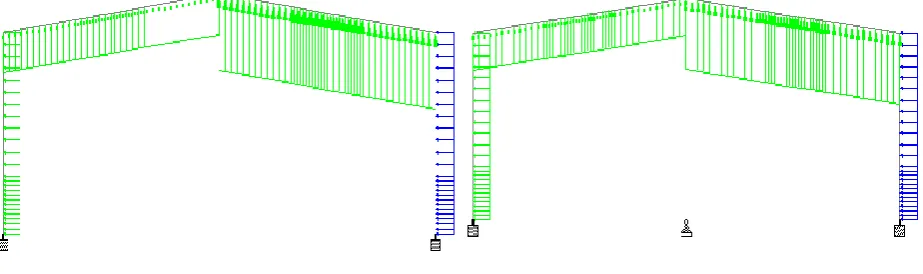
TCCS frame TCMS1 frame
Figure1 PEB frames TCCS & TCMS1
IV. LOAD CALCULATION, COMBINATION AND DEFLECTION CRITERIA
4.1.0 Design Detail Specification
Location of building = Kolkata
Length of building= 324 m Width of building= 40m
Intermediate column at = 20m Bay spacing = 9 m
Eave Height (clear) = 9.5m
Seismic Zone = III Wind Speed = 50 m/s Terrain category = Category 2 Slope = 1:10
Soil type = Medium
Response reduction factor = 4 Importance factor = 1.
4.1.1Dead Load
Dead Load = .15 kN/m2 As per IS 875 Part1 Total dead load =.15*9(Bay Spacing)
=1.35 kN/m
4.1.2Live Load
Live Load =.75 kN/m2As per IS 875 Part2
Total Live Load =.75*9(Bay Spacing) = 6.75kN/m
4.1.3Earthquake Load
Dead Load = .15 kN/m2As per IS 875 Part2
Live load = .1875kN/m2(25% live load considered as per IS 1893 (part1):2002) Total load = .3375 kN/m2
ISSN(Online): 2319-8753 ISSN (Print): 2347-6710
I
nternational
J
ournal of
I
nnovative
R
esearch in
S
cience,
E
ngineering and
T
echnology
(An ISO 3297: 2007 Certified Organization) Website: www.ijirset.com
Vol. 6, Issue 7, July 2017
4.1.4Wind load calculation
Basic wind speed = 50 m/sec Risk coefficient (k1) = 1
Terrain height & size factor (k2)= 1 Topography factor (k3)= 1
Importance factor (k4) =1
Design wind speed (Vz) =Vb x K1 x K2 x K3 x K4 =50 m/s
Design wind pressure (pz) = 0.6x (Vz)2
pz= 1.5KN/m²
Design wind pressure (Pd) = Kd*Ka*Kc*pz> 0.7pz
Wind directionality factor (Kd) = 1 Area averaging factor (Ka) =0.9 Combination factor (Kc) = 1
Design wind pressure (Pd) = 1.35 kN /m2
Wind load is applied as per IS 875 part 3. The wind load is applied as uniformly distributed load acting away from the structure over roof. For side wall, the wind load is applied as uniformly distributed load acting away and toward to the structure according to the wind load cases.
Figure 2 Wind load on TCCS & TCMS1frames
4.1.5 Parameters for Intermediate concrete filled steel tubular (CFST) column Limiting values for CFST as per BS-5400 part 5
1. The wall thickness of concrete filled steel tube should not be less than De
s y
E
f
8
for circular section.
2. The concrete should be of normal density (Not less than 23 kN/m3) with characteristic 28 day cube strength of not
less than 20 N/mm2 for concrete filled tube.
3. The ratio of effective length to its least lateral dimension should not exceed 55 for concrete filled circular section.
ISSN(Online): 2319-8753 ISSN (Print): 2347-6710
I
nternational
J
ournal of
I
nnovative
R
esearch in
S
cience,
E
ngineering and
T
echnology
(An ISO 3297: 2007 Certified Organization) Website: www.ijirset.com
Vol. 6, Issue 7, July 2017
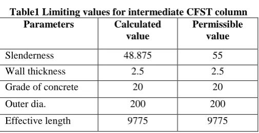
Table1 Limiting values for intermediate CFST column
Circular hollow tube is used as an intermediate column for taking axial load because it is pin supportedat mid of
building. In above table effective length 9.775m, wall thickness 2.5mm, yield strength 250 N/mm2 these parameters
are used for analysis CFST column as per BS-5400.
4.1.6 Analysis of CFST intermediate column by British Standard Equation
Axially load column formed from concrete filled circular hollow steel tube. The axial load is calculated by BS-5400 Squash load equation of CFST column by BS-5400 part 5
Nu = 0.95*fy’*As +0.45*fcc*Ac Where
fcc= is an enhanced characteristic strength of tri-axially contained concrete under axial load
fcc = fcu + C1*t*fy
De
f’y=is a reduction nominal yield strength of steel casing
f’y = C2*fy
fyYield strength of steel tube material (250 N/mm2)
As Cross sectional area of steel tube (mm2)
Ac Cross section area of concrete in tube (mm2)
fcu is the characteristic 28 day cube strength of the concrete (20 N/mm2)
Esis the modulus elasticity of steel (2*E+005 N/mm2)
Table 2 Values of constants C1 & C2 for axially loaded CFST circular column
Le/De C1 C2
0 9.47 0.76
5 6.40 0.80
10 3.81 0.85
15 1.80 0.90
20 0.48 0.95
25 0 1.0
4.1.7 Concrete Contribution Factor
The concrete contribution factor lies between the following limit For concrete filled hollow steel sections 0.1 < αc < 0.8
Where αc = 0.45*Ac*fcu
Nu
Nu = Squash load
αc =Concrete contribution factor
Parameters Calculated value
Permissible value
Slenderness 48.875 55
Wall thickness 2.5 2.5
Grade of concrete 20 20
Outer dia. 200 200
ISSN(Online): 2319-8753 ISSN (Print): 2347-6710
I
nternational
J
ournal of
I
nnovative
R
esearch in
S
cience,
E
ngineering and
T
echnology
(An ISO 3297: 2007 Certified Organization) Website: www.ijirset.com
Vol. 6, Issue 7, July 2017
4.1.8 Pre-Engineering Building by Staad. Pro.
Staad pro. is the most popular tool for analysis and design of 2D & 3Dstructure modeling with various properties. The procedure for design of structure modeling, specification to structure, support, loading and load combination, of analyzing and design of the structure. Staad pro software is not only for building analysis but also facilities available for bridge analysis. In staad pro utilization ratio indicates the suitability of the member as per code, the value above 1 is indicates not suitable for given load, and the value below 1 indicates the member capacity available. Staad pro also gives the other useful information about the structure that it fail in compression, tension, slenderness, flexural and shear. In staad Pro. is the powerful tool by which, structure can be designed with various material, properties, and any desirable properties can be generate.
4.1.9 Load combination and deflection limit as per IS code
Load combinations include different combination of loads according to IS 800-2007 by considering serviceability and strength criteria.
Table 3 Load Combination as per IS: 800-2007
S.No. Limit state of serviceability Limit state of strength
1 2 3 4 5 6 7 8 9 10 11 12
DL+LL DL+WL DL+EQ
DL+0.8LL+0.8WL DL+0.8LL+0.8EQ
1.5(DL+LL) 1.5(DL+WL) 1.5(DL+EQ) 0.9DL+ 1.5WL 0.9DL+1.5EQ 1.5DL+1.05LL 1.5DL+1.05LL 1.2DL+1.2LL+0.6WL 1.2DL+1.2LL+0.6EQ 1.2DL+1.05LL+0.6WL 1.2DL+1.05LL+0.6WL 1.2DL+0.5LL+2.5EQ 0.9DL+2.5EQ
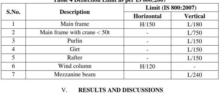
In table3, the load combinations for limit state of serviceability & limit state of strength are applied to the TCCS & TCMS1 as per IS800-2007. Higher factor to the load combination is also the reason to increase the weight. In table 4 deflection limit is applied to the all frames for every member.
Table 4 Deflection Limit as per IS 800:2007
S.No. Description Limit (IS 800:2007)
Horizontal Vertical
1 Main frame H/150 L/180
2 Main frame with crane < 50t - L/750
3 Purlin - L/150
4 Girt - L/150
5 Rafter - L/150
6 Wind column H/120 -
7 Mezzanine beam L/240
V. RESULTS AND DISCUSSIONS
ISSN(Online): 2319-8753 ISSN (Print): 2347-6710
I
nternational
J
ournal of
I
nnovative
R
esearch in
S
cience,
E
ngineering and
T
echnology
(An ISO 3297: 2007 Certified Organization) Website: www.ijirset.com
Vol. 6, Issue 7, July 2017
combination and compare the weights by using Staad pro. And British Standard BS-5400 part 5 is used for calculating load of pin ended intermediate column.
Table 5 Load calculated of Intermediate HSTC by Staad.
HSTC
Shape fy(N/mm2)
Wall thickness
tw(mm)
De Outer dia. (mm) Axial load (kN)Staad. TCMS1 Frame wt. (ton) TCCS Frame wt. (ton) I.C column wt. (ton)
Circular 250 3 300 284.78 6.66 4.35 .247
The most important parameter in this study, Intermediate circular column, once TCMS1 frame is analyzed with circular hollow steel tubular column (HSTC) and second TCMS1 frame is analyzed with concrete filled steel tubular column (CFST) and compare the weight between frames and intermediate columns. For CFST column capacity, M20 grade of concrete is filled in steel tube for taking the effect of confinement of concrete and axial load capacity by using BS-5400 part 5.
Table 6 Load calculation by BS-5400 part 5
CFST column or composite columnis the advanced application in Pre-Engineering Building due to which a significant weight can be reduced. In table 6, And axial load for circular concrete filled steel tubular column is calculated by BS-5400 part 5, CFST column is more capable to take axial load higher than HSTC because concrete strength and confinement of concrete are play the important role to increasing the strength of CFST column.In short column, tri axial strength is the most important factor, CFST column ismore capable to take the large axial load than circular hollow steel tube due to tri-axial strength.
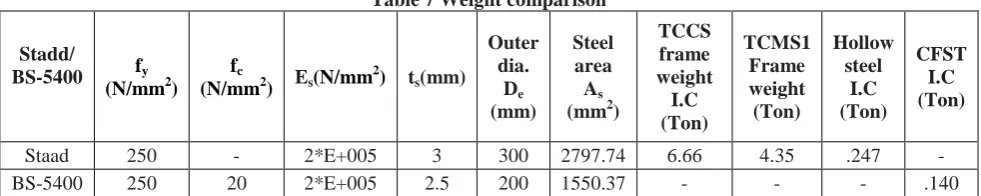
Table 7 Weight comparison
Stadd/
BS-5400 fy
(N/mm2) fc
(N/mm2) Es(N/mm
2) t
s(mm) Outer dia. De (mm) Steel area As (mm2)
TCCS frame weight I.C (Ton) TCMS1 Frame weight (Ton) Hollow steel I.C (Ton) CFST I.C (Ton)
Staad 250 - 2*E+005 3 300 2797.74 6.66 4.35 .247 -
BS-5400 250 20 2*E+005 2.5 200 1550.37 - - - .140
In above results, concrete filled steel tubular column and hollow steel tubular column are used as intermediate columns for knowing the behavior of frame, frame weight. Results shows above, CFST column is more capable to take the higher load than HSTC column with lesser weight, economical, and more efficient. In this paper, the support condition for TCCS frame and TCMS1 frame is fixed, TCCS frame weight much higher than TCMS1frame due to higher moments are generated at fixed supports,negative moments at column rafter end and deflection at mid span.In TCMS1, two different type of intermediate column are used hollow steel tubular & concrete filled steel tubular column. Axial load in intermediate circular hollow steel tubular column is taking from staad.
CFST column shape fy (N/mm2) fc
(N/mm2)
Wall thickness tw Slenderness ratio De outer dia. (mm) Axial Load (kN) Staad Calculated Load by BS
code (kN)
CFST I.C wt.(ton)
ISSN(Online): 2319-8753 ISSN (Print): 2347-6710
I
nternational
J
ournal of
I
nnovative
R
esearch in
S
cience,
E
ngineering and
T
echnology
(An ISO 3297: 2007 Certified Organization) Website: www.ijirset.com
Vol. 6, Issue 7, July 2017
Weight comparison between TCMS1& TCCS Weight comparisons between HSTC & CFST
Figure 3 Weight comparison
In above graph, in fig.3 weight comparison between tapered column multi span one and tapered column clear span frame. The weight ofTCMS1 with circular hollow steel tubular and concrete filled steel tubular column is less than TCCS frame. In next fig. the weight, strength, and buckling capacity of concrete filled steel tubular column is more efficient than HSTC.
VI. CONCLUSION
1. Tapered column clear span (TCCS) frame is almost 34% heavier than tapered column multi span one(TCMS1)
with hollow steel tubular column at ridge.
2. Tapered column clear span (TCCS) frame is almost 36% heavier than tapered column multi span one (TCMS1)
with concrete filled steel tubular (CFST) column at ridge.
3. Hollow steel tubular column is 43% heavier than concrete filled steel tubular column (CFST) in TCMS1 frame.
4. In TCMS1, consumption of steel in CFST column much lesser than hollow steel tubular column. Not only lesser
steel consumption but also provide higher load carrying capacity, confinement of concrete, good ductility and low cost.
5. Overall TCMS1frame with CFST column at ridge is proved more efficient and economical, good ductility higher
load capability than other frames.
6. Steel quantity depends on primary members & purlins. As bay spacing of frames is increased steel consumption
decreased for primary member and increased for secondary members up to certain limit.
REFERENCES
1. Pre-Engineered Metal Buildings the latest trend in building construction” By K.K.Mitra – Gen. Manager (marketing) Lloyd Insulations (India) Limited.
2. Neha R. Kolate, ShilpaKewate“Cost Effectiveness of Pre-engineered and Conventional Steel Frames”, International Journal of Innovative Research in Science, Engineering and Technology, ISSN:2319-8753, volume 4 Issue 8, 2015
3. Swati Wakchaure, N.C Dubey“Design and Comparative Study of Pre-Engineered Building”, International journal of Engineering development and research-( IJEDR) ISSN:2321-9939 volume 4, Issue 2, 2016
4. G. Sai Kiran, A. kailasaRao, R. Pradeep Kumar, “ Comparison of Design Procedures for Pre-Engineering Buildings(PEB): A case study”, International Journal of Civil, Environmental, Structural, Construction and Architectural Engineering, Volume 8 issue 4,2014
5. C. M. Meera,”Pre-Engineered Building Design of an IndustrialWarehouse”, international journal of engineering sciences & emergingtechnologies, volume 5, Issue 2, pp: 75-82. 2013
6. N. Subramanian, Design of Steel Structures
7. IS: 875 (Part 1)-1987 Code of Practice for design loads (other than earthquake) for buildings and structures (Dead load). 8. IS: 875 (Part 2)-1987 Code of Practice for design loads (other than earthquake) for buildings and structures (Imposed load).
0 1 2 3 4 5 6 7
TCMS1 TCCS
WEIGHT
0 0.05 0.1 0.15 0.2 0.25 0.3
HSTC CFST
ISSN(Online): 2319-8753 ISSN (Print): 2347-6710
I
nternational
J
ournal of
I
nnovative
R
esearch in
S
cience,
E
ngineering and
T
echnology
(An ISO 3297: 2007 Certified Organization) Website: www.ijirset.com
Vol. 6, Issue 7, July 2017
9. IS: 875 (Part 3)-2015 Code of Practice for design loads (other than earthquake) for buildings and structures (Wind load) 10. IS: 800-2007 Indian Standard General Construction in Steel – Code of Practice.
11. IS: 801-1975 Code of practice for use of Cold formed light gauge steel Structural members in general building construction. 12. BS 5400 part5-2005 Code of practice for the design of composite bridges.
13. BS 5400 part4-1984 Code of practice for the design of concrete bridges.
BIOGRAPHY
MOHD AHTASHAM has received his B.Tech. in Civil Engineering from B.B.D N.I.T.M
Lucknow & M.Tech. in Structural Engineering from N.I.T Srinagar J & K. He is presently working in Apex Buildsys, Noida, India. His research interests include Bridge
Engineering,RCC Design & Steel Structures. He is a chartered Engineer from Institution of