PI Controller Over IP Network
Yodyium Tipsuwan
, Member, IEEE,
and Mo-Yuen Chow
, Senior Member, IEEE
Abstract—The potential use of networks for real-time high-per-formance control and automation is enormous and appealing. Replacing a widely used proportional-integral (PI) controller by a new networked controller for networked control capability can be costly and time-consuming. This paper proposes a methodology based on gain scheduling with respect to real-time IP traffic conditions to enhance the existing PI controller so it can be used over IP networks with a general network protocol like Ethernet. This paper first describes the gain scheduling approach based on constant network delays using a rational function approach. The formulation is extended to random IP network round-trip time (RTT) delays by using the generalized exponential distribution model. Simulation results show that the PI controller with gain scheduling provides significantly better networked control system performance.
Index Terms—Adaptive control, control systems, dc motors, dis-tributed control, Internet, networks, real-time system.
I. INTRODUCTION
A
N ADVANCING trend is to substitute specialized indus-trial networks with a general network such as Ethernet to control applications in distributed control, industrial electronics, and factory automation areas remotely over an Internet Protocol (IP) network [1]–[3]. A protocol like Ethernet has several ad-vantages due to its well-developed infrastructure, widespread usage, and affordability, for IP connection. Of course, a con-troller can be connected to a plant to form a local closed-loop control system and the status of the system can be monitored via an IP network as well as simple on-off control. However, this configuration does not have good interaction with an operator or an automatic controller located on a remote side. When an anomaly occurs, the remote side can only notice it from reported messages and may not be able to respond in time. Researchers have proposed a scheme to have a controller connected to a plant via a network as a closed-loop networked control system [1] so that the remote controller could interact with the plant via the network more quickly. Several methodologies on this topic have been developed to handle the time-varying network delay effects. These methodologies are based on various tech-niques such as state augmentation [4], optimal stochastic controlManuscript received January 20, 2004; revised May 4, 2004. This work was supported in part by the Royal Thai Government.
Y. Tipsuwan was with the Department of Electrical and Computer Engi-neering, North Carolina State University, Raleigh, NC 27695-7911 USA. He is now with the Department of Computer Engineering, Kasetsart University, Bangkok, 10900 Thailand (e-mail: [email protected]).
M.-Y. Chow is with the Department of Electrical and Computer Engineering, North Carolina State University, Raleigh, NC 27695-7911 USA (e-mail: [email protected]).
Digital Object Identifier 10.1109/TMECH.2004.834645
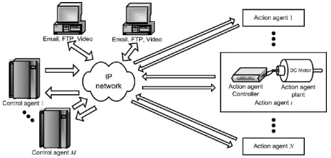
Fig. 1. Overall distributed networked control system over an IP network.
[5], nonlinear control [6], robust control [7], buffering and pre-diction [8], [9], Smith predictor [10], event-based control [11], sampling time scheduling [12], [13], optimal gain scheduling [14], scattering transformation [15], and fuzzy logic [16], [17]. Many of these techniques require a completely redesigned con-troller to handle network delays. Practical concon-trollers that exist in industrial applications such as a proportional-integral (PI) controller have to be replaced. This replacement is time-con-suming and costly.
This paper proposes a methodology that enhances the widely used PI controller so it can be used over IP networks with a general computer protocol like Ethernet without requiring re-design and reinstallation of a new networked control system. The proposed approach is based on PI controller gain sched-uling. The optimal PI controller gains are scheduled in real time with respect to the monitored IP network traffic condition in order to maintain the best possible system performance. There-fore, changes in IP network traffic conditions are always cap-tured by the proposed approach.
II. SYSTEMDESCRIPTION
A. System Configuration
In this paper, we consider a distributed networked control system configured over an IP network as shown in Fig. 1.
1) IP Network: The IP network under consideration links all networked control devices. In this paper, we assume that the net-worked control devices use the User Datagram Protocol (UDP) as the layer-4 protocol on the IP network to avoid additional de-lays from retransmissions.
2) Control Agent: Each control agent can be a high-perfor-mance computing unit to manage operations of action agents. In this paper, we consider one of the control agents that uses a PI controller to control each action agent in the low level. Periodi-cally, the control agent converts the sensory signals in a packet sent across the IP network from each action agent to numerical
Fig. 2. Point-to-point networked control system formulation.
feedback data for a PI control response. The control signal from the PI controller is then sent back as a packet to each action agent via the IP network as well.
3) Action Agent: Each action agent contains an action agent controller and an action agent plant. The action agent controller is a simple hardware unit to periodically convert the control signal in a packet from the control agent to an actual signal to drive the action agent plant. The sensory output of the action agent plant such as motor speed is also monitored and sent back to the control agent.
B. Mathematical Formulation
In order to analyze how to schedule the PI controller gains on the control agent with respect to an IP network traffic con-dition, let us consider an action-agent–control-agent pair and formulate the problem mathematically in a continuous-time ap-proach by firstassumingIP network delays are constant. A typ-ical single networked control system is formulated as shown in
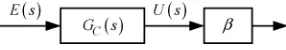
Fig. 2, where , , , and are
the reference, control, output, and error signals in Laplace do-main, respectively. The other action agents and control agents can be controlled using a similar formulation.
The action agent plant dynamics is expressed as a transfer function , where the PI controller is described by
(1)
where and are the proportional gain and integral gain, respectively, and is a constant. The network delays for sending the control to the action agent plant , and for sending the system output to the PI
con-troller , are represented by and ,
re-spectively, of which the analytical forms are
(2) (3)
where and are the delay from the controller to the plant, and the delay from the plant to the controller in time do-main, respectively. The closed-loop transfer function including the network delays becomes
(4)
In order to analyze the closed-loop control system with net-work delay effects, a typical approach is to use a rational func-tion with the numerator degree zero to approximate the delays as follows [18]:
(5)
Fig. 3. Adaptation of PI controller gains at the controller output by.
where can be or . This approximation is adequate for many practical applications, because the primary branches of the system root locus usually contain the dominant eigenvalues of the system [18]. Moreover, (5) is suitable for real-time appli-cations due to its computational simplicity.
C. Case Study
A dc motor speed control problem is used as a case study to demonstrate the proposed approach throughout this paper. The dc motor transfer function from [19] is used to represent the action agent plant dynamics, and is described by
(6)
Let us assume that the practical dc motor PI speed controller is designed and tuned without concerning for the network delays to have the relative damping ratio of 0.707 and to satisfy the following specifications with the step response:
1) Percentage overshoot (P.O.): ; 2) Settling time : s;
3) Rise time : s.
Using the root locus design approach without considering network delays, a feasible choice of
, and these gains satisfy all the design specifica-tions as listed.
III. PARAMETERIZATION FOR GAINSCHEDULING: CONSTANTNETWORKDELAY
A. PI Controller Parameterization
With network delays in the control loop, the initial
may no longer satisfy the specifications. The system perfor-mance will degrade, and the system may become unstable. To maintain the best possible system performance with network delays, the controller gains need to be adapted with respect to the current network condition. In this section, we introduce the gain to externally adapt without completely re-designing the existing controller. The idea of gain adaptation is adopted from [20]. The gain has to be greater than zero to avoid positive feedback. The gain is placed in front of the ini-tial PI controller as depicted in Fig. 3.
Analytically, adjusts both and , while keeping the ratio between both gains at as follows:
(7)
this approach may not be suitable for real-time on-line analysis. In addition, by searching for instead, the feasible region is only one dimensional, which makes it easier to search for the optimal value.
B. Optimizing
In order to evaluate the best possible system performance with respect to under different IP network conditions, we min-imize the following cost function to find the optimal :
(8)
(9)
(10)
(11)
where
(12)
is the mean-squared error, is the nominal mean-squared error, is the nominal percentage overshoot, and is the nominal rise time. The weights , , and are used to specify the relative significance of , , and , respec-tively, on the overall system performance. The error
is computed by sampling at , where is the sampling period, and is the time index. The costs , , and are mainly used to provide the penalty when the system performance degrades from the nominal system performance. In this case, the nominal performance can be adopted from the design specifications mentioned earlier such that , , whereas has to be determined from a simulation or an experiment. In this paper, we use
. Therefore, when without network delays in the
system, .
With network delays, may no longer be optimal. Thus, the optimal gain has to be obtained by evaluating with con-cern for current network delays. Unfortunately, usually does not have a closed-form relationship with . Therefore, a feasible approach to search for the optimal is to rely on a simulation according to the feasible set of . We define as the feasible set containing all that do not cause system instability. The fea-sible set can be estimated by the root locus analysis and the approximation in (5) with the following approximated charac-teristic equation:
(13)
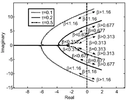
Fig. 4. Primary branches of the root locus of the networked dc motor PI speed control system using the approximation in (5) to approximate delays.
where is defined as . For example, setting , the root locus of (13) with respect to
and are shown in Fig. 4. Only the primary branches of the root locus are shown in Fig. 4 to determine the stability of the closed-loop system. As discussed in [18], the primary branches are sufficient to be used for stability region approximation.
In a stable system, can range from 0 to the value at which the root locus crosses the imaginary axis. Thus, can be defined as , where is the gain at the point that the root locus crosses the imaginary axis with respect to . In fact, does not need to be very precise since the optimal is unlikely to be close to . If is closed to , and can be very large because the closed-loop system is nearly unstable. As indicated in Fig. 4,
becomes smaller and less sensitive to when increases. This implies that a longer delay gives a smaller feasible set . Simple search for the optimal for a specific can be easily accomplished by iteratively running simulations with various in the feasible region, and comparing the cost to optimize for
. Various optimization methods could be used for . In this paper, for example, we optimize by a lookup table approach using (2) and (3) as delays for and , respectively, in
simulations with , , ,
s, where the final time for simulations s. The cost from this optimization is shown in Fig. 5. As shown in Fig. 5, when the delay is longer, the optimal shifts to the left, and becomes moresensitiveto .
IV. PARAMETERIZATION FORGAIN SCHEDULING: ACTUALIP NETWORKDELAY
A. IP Network Delay Characteristics
Fig. 5. CostJfrom optimization using (2) and (3) to delayU(s)andY (s), respectively, withw = 1:64902,w = 0:00833,w = 0:01395,t = 10s,
= 0:1; 0:2; 0:6s.
TABLE I
STATISTICALMEASURES(MINIMUM, MEDIAN, MEAN,ANDMAXIMUM)OF RTT DELAYSMEASUREDFROMADAC LAB ATNCSUTOwww.lib.ncsu.edu,
www.visitnc.com, www.utexas.edu,ANDwww.ku.ac.th
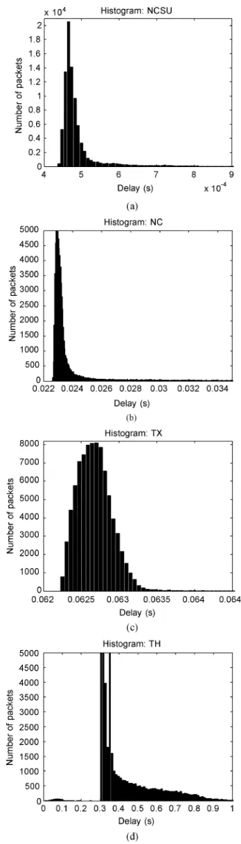
(00:00–24:00). Statistical measures of the RTT delays are also shown in Table I. The corresponding histograms of the RTT de-lays to approximate probability densities are shown in Fig. 6.
B. Parameterization of IP Network Delay Characteristics for Gain Scheduling
Fig. 6 shows that the histograms skew to the left. These shapes of the histograms indicate the higher probability to have RTT delay that is shorter than the median and mean. RTT delay can be much longer than the median and mean, but with much lower probability. In this paper, we will focus more on well-regulated traffic IP networks with a small number of hops that have the probability density of RTT delay similar to Fig. 6(a) and (b). To investigate how this stochastic behavior can affect the op-timality of , RTT delay is modeled by a random probability distribution. The random distribution model should be simple in order to estimate in real time for gain scheduling, while pro-viding reasonable accuracy in representing different IP network conditions. Based on these reasons, we propose to use the gen-eralized exponential distribution to describe IP network delays as follows:
(14)
where the expected value of the RTT delay , and variance . If is known, can be easily approximated from and an experimental value of or the mean . Some
Fig. 6. Histograms of RTT delays measured from ADAC Laboratory at NCSU to: (a) www.lib.ncsu.edu; (b) www.visitnc.com; (c) www.utexas.edu; (d) www.ku.ac.th.
Fig. 7. Typical effect of variouson the optimalselecting while holding constant at = 0:01.
and parameters have to be updated frequently with respect to the current IP traffic condition. This concern relates to how to generalize the approach based on a constant in the pre-vious section. RTT delay can be treated as the delay except that RTT delay is stochastic and happens as discrete events. In this paper, we treat the IP network stochastic behavior as a pa-rameter variation of the system transfer function. Therefore, should be an appropriate value to serve as a base for the param-eter variation described as , where is the delay parameter variation. Also, based on (14), should be the peak of the probability density function. A feasible choice of is the median of RTT delay. The median can be easily com-puted in real time and is representative for a majority of RTT delay. For example, the medians in Table I are very representa-tive because they locate closely to the peaks of the histograms in Fig. 6, which are the majority of RTT delays. We ignore the case (i.e., ) since this variation is relatively small. In addition, could be used as the worst case RTT delay distribution for . Based on (14) and the RTT delay statis-tics, we also assume that RTT delays have .
C. Optimizing With Actual IP Network Delay Concern
If RTT delay is constant, will be zero, and the optimal for can be immediately applied. With the stochastic behavior of actual IP networks, could affect the optimal setting of the PI controller as the delay transfer functions in the control loop are changed. Thus, the optimal under different actual IP network traffic conditions has to be evaluated with respect to the updated and . To find the optimal with respect to the updated and , the same iterative simulation approach as for constant delays can be used except that the delay has to vary by the general-ized exponential distribution in (14) with given and . In ad-dition, the PI controller in simulations has to be a discrete-time controller to support actual IP packet transmission, but
obtained from the root locus in the continuous-time domain can still be used to approximate feasible regions. Fig. 7 shows the
cost with respect to while holding
. In addition, the surfaces of with respect to various
Fig. 8. Typical cost surfaces ofJ with respect to variousandwithout constraint.
TABLE II
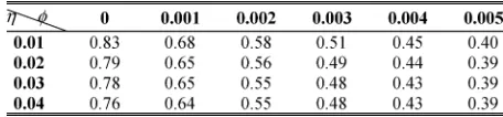
OPTIMALWITHRESPECT TO = 0:01; 0:02; 0:03; 0:04;AND
= 0; 0:001; 0:002; . . . ; 0:005OBTAINEDWITHw = 1:64902,
w = 0:00833,w = 0:01395, WITHOUTCONSTRAINT
and obtained from the same condition are shown in Fig. 8. Some of the optimal found from are shown in Table II. As shown in Figs. 7 and 8 and Table II, the optimal shifts to the left and decreases in value when there is more delay variation indicated by a higher value of . A higher also lowers the op-timal .
V. GAINSCHEDULINGALGORITHM
A possible solution to handle the variable traffic condition on actual IP networks is to adjust by scheduling with respect to the current traffic condition characterized by and . We assume that the gain scheduling approach is implemented as a hardware or software part of the control agent called the scheduler middleware, which is physically (in hardware) or virtually (in software) attached in front of the original PI con-troller, respectively. The gain scheduling procedure is depicted in Fig. 9 with steps 1, 2, 3, 4, and 5, described as follows.
Step 1) The gain scheduler middleware initializes the packet index defined as , to , the summation of RTT delay defined as to , and the number of successful packet roundtrips defined as to to be used in later steps.
Fig. 9. gain scheduler middleware operation.
reference. The packet is sent out immediately if possible. How-ever, the network may not be always available for a transmis-sion. Thus, the packet may have to be stored in the output queue to wait for sending at the instant that the IP network is ready. Once the packet is pushed in the queue, or sent out im-mediately without being stored, the scheduler middleware will increase the packet index by .
Step 3) The action agent will return the output , , and , as a packet back to the scheduler middleware once it receives and processes periodically using the sampling period . This corresponding feedback is defined as . Likewise, we assume the action agent has the same queueing mechanism to handle outgoing packets.
Step 4) When the scheduler middleware receives a packet containing from the action agent at time during a sam-pling period, the scheduler middleware will compute
(15) (16) (17)
where is the RTT delay of the packet roundtrip , and is the arrival time of the corresponding feedback packet . The summation of is used to later compute the mean . The scheduler middleware will store in memory along with other RTT denoted as , that are previ-ously computed. The RTT delay is placed in the memory,
at which , , for sorting
RTT delays in the memory to later compute . For future ref-erence, the RTT delay stored at the position in the memory is defined as . Packets transmitted between the sched-uler middleware and an action agent may be lost because of sev-eral reasons such as IP network congestion and a router’s packet dropping policy. Therefore, there would be some unsuccessful packet roundtrips. In this case, the PI controller and the action agent will opt to use the most updated data to compute and , respectively. Out-of-order packets will be ignored. In this paper, we focus on the effect of IP network delay and variation, and assume that the number of unsuccessful packet roundtrips is small such that it does not significantly affect the control performance.
Step 5) Once , the scheduler middleware will calculate
(18)
Fig. 10. gain scheduler middleware simulation.
is even is odd (19)
(20)
where is the number of packets used to approximate the char-acteristic of RTT delay. When , and becomes the representative worst case delay to avoid a negative , which violates the shape of (14). The scheduler middleware then up-dates by picking the optimal from the table with respect to
and . Steps 1–5 will be repeated for the next iteration.
VI. SIMULATIONRESULT
The performance of the proposed scheduler middleware ap-proach on the networked dc motor PI speed control system is verified by simulations implemented on Matlab/Simulink 6.1 as shown in Fig. 10. The following environment is used to illus-trate the effectiveness of the proposed scheduler middleware control scheme.
• The steady-state reference value: . • The final simulation time: s.
• The size of the optimal lookup table is 14 26, where
, and
. The optimal from and that is not in the table is obtained by the linear-interpola-tion technique.
• The sampling time of the PI controller, the scheduler middleware, and the action agent controller: ms. • The number of packets to evaluate the characteristic of
RTT delay: .
To investigate the effectiveness of the scheduler middle-ware on actual RTT delays, the three scenarios are simulated by the RTT delay data sets measured from ADAC Lab at NCSU to the destinations in Table I.
1) The dc motor is controlled over IP networks by the PI controller with the nominal gains .
2) The dc motor is controlled over IP networks by the PI controller with a fixed . The fixed is obtained by pre-estimating and from an RTT delay data set.
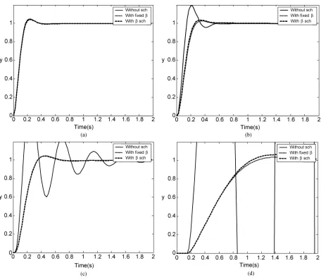
Fig. 11. Step responses from networked dc motor PI speed control simulations using RTT delays from ADAC Laboratory at NCSU to: (a) www.lib.ncsu.edu; (b) www.visitnc.com; (c) www.utexas.edu; (d) www.ku.ac.th.
all data points in an RTT delay data set by two, and se-lecting some values from this set to apply as , and . Each value of chosen from data points in the RTT data set is different from the data points used for . The costs from the simulations with actual RTT delays on the three scenarios are shown in Table III, whereas the step responses from the simulations are il-lustrated in Fig. 11.
The performance of the PI controller using the nominal gains is significantly lower when RTT delay is longer and its varia-tion is larger as shown in Table III and Fig. 11. The networked PI control system using fixed and scheduler middleware could maintain the system performance much better. As shown in Table III and Fig. 11(a), all control schemes can satisfy the performance requirements by resulting in because RTT delay and its variation are relatively low. With longer RTT delay and more delay variation, the requirements cannot be satisfied as shown in Table III and Fig. 11(b) and (c). Nevertheless, the fixed and scheduler middleware schemes can still main-tain the system performance satisfactorily. The performance is much better than the system with the nominal since the PI controller gains in this case are adapted to be more
suit-TABLE III
COSTSJFROMNETWORKEDDC MOTORPI SPEEDCONTROLSIMULATIONS USINGRTT DELAYSFROMADAC LABORATORY ATNCSUTO www.lib.ncsu.edu, www.visitnc.com, www.utexas.edu,ANDwww.ku.ac.th
able for the network traffic conditions. However, as shown in Table III and Fig. 11(d), both schemes cannot perfectly main-tain the system performance to meet the specifications with very long RTT delay and very high variation, but can still reasonably stabilize the networked control system.
density of RTT delay may vary, and sometimes the variation can be large. Therefore, the fixed optimal gain approach may no longer be suitable in some situations such as IP network con-gestion. Using the gain scheduling middleware to adjust the PI controller gains could provide an acceptable and more flex-ible control in real IP environment.
VII. CONCLUSION
A gain scheduling approach with respect to the current net-work traffic condition is introduced in this paper to enhance widely used and existing PI controllers for using over IP net-works. Simulation results have shown the promising chances to apply the proposed gain scheduling scheme for a networked PI controller on actual IP network environment with reason-ably long RTT delays and relatively low variations. There are still several issues to be investigated in order to improve and strengthen the gain scheduling approach such as packet loss effects and the performance of the gain scheduling on actual networked control systems over real IP networks under various IP quality-of-service (QoS) protocols. These additional studies could support the gain scheduling approach for practical uses in the future.
REFERENCES
[1] Y. Tipsuwan and M.-Y. Chow, “Control methodologies in networked control systems,”Contr. Eng. Practice, vol. 11, no. 10, pp. 1099–1111, 2003.
[2] G. Kaplan, “Ethernet’s winning ways,”IEEE Spectrum, vol. 38, pp. 113–115, Jan. 2001.
[3] F.-L. Lian, J. R. Moyne, and D. M. Tilbury, “Performance evaluation of control networks: Ethernet, ControlNet, and DeviceNet,”IEEE Control Syst. Mag., vol. 21, pp. 66–83, Feb. 2001.
[4] Y. Halevi and A. Ray, “Integrated communication and control systems: Part I—Analysis,” J. Dynamic Syst., Meas., Contr., vol. 110, pp. 367–373, 1988.
[5] J. Nilsson, “Real-time control systems with delays,” Ph.D. dissertation, Lund Inst. Technol., Lund, Sweden, 1998.
[6] G. C. Walsh, H. Ye, and L. G. Bushnell, “Stability analysis of net-worked control systems,”IEEE Trans. Contr. Syst. Technol., vol. 10, pp. 438–446, May 2002.
[7] F. Goktas, “Distributed control of systems over communication net-works,” Ph.D. dissertation, Univ. Pennsylvania, Philadelphia, PA, 2000. [8] R. Luck and A. Ray, “An observer-based compensator for distributed
delays,”Automatica, vol. 26, no. 5, pp. 903–908, 1990.
[9] H. Chan and H. Ozguner, “Closed-loop control of systems over a com-munication network with queues,”Int. J. Control, vol. 62, no. 3, pp. 493–510, 1995.
[10] M. L. Sichitiu, “Control of data networks: Models, stability and con-trollers,” Ph.D. dissertation, Univ. Notre Dame, Notre Dame, IN, 2001. [11] T.-J. Tarn and N. Xi, “Planning and control of Internet-based teleopera-tion,” inProc. SPIE: Telemanipulator and Telepresence Technologies V, vol. 3524, Boston, MA, 1998, pp. 189–193.
[12] S. H. Hong, “Scheduling algorithm of data sampling times in the inte-grated communication and control systems,”IEEE Trans. Contr. Syst. Technol., vol. 3, pp. 225–230, June 1995.
[13] Y. H. Kim, H. S. Park, and W. H. Kwon, “Stability and a scheduling method for network-based control systems,” inIEEE Int. Conf. Indus-trial Electronics, Control, and Instrumentation (IECON’96), vol. 2, Taipei, Taiwan, 1996, pp. 934–939.
[14] M.-Y. Chow and Y. Tipsuwan, “Gain adaptation of networked DC motor controllers based on QoS variations,”IEEE Trans. Industr. Electron., vol. 50, pp. 936–943, Oct. 2003.
[15] N. Chopra, M. W. Spong, S. Hirche, and M. Buss, “Bilateral teleopera-tion over the Internet: the time varying delay problem,” inIEEE Auto-matic Control Conf. (ACC’03), vol. 1, Denver, CO, 2003, pp. 155–160. [16] K. C. Lee, S. Lee, and M. H. Lee, “Remote fuzzy logic control of net-worked control system via Profibus-DP,”IEEE Trans. Industr. Electron., vol. 50, pp. 784–792, Aug. 2003.
[17] N. B. Almutairi, M.-Y. Chow, and Y. Tipsuwan, “Network-based controlled DC motor with fuzzy compensation,” inIEEE Int. Conf. Industrial Electronics, Control, and Instrumentation (IECON’01), vol. 3, Denver, CO, 2001, pp. 1844–1849.
[18] B. C. Kuo,Automatic Control Systems, 5 ed. Englewood Cliffs, NJ: Prentice-Hall, 1987.
[19] Y. Tipsuwan and M.-Y. Chow, “Fuzzy logic microcontroller implemen-tation for DC motor speed control,” inIEEE Int. Conf. Industrial Elec-tronics, Control, and Instrumentation (IECON’99), vol. 3, San Jose, CA, 1999, pp. 1271–1276.
[20] N. B. Almutairi and M.-Y. Chow, “A modified PI control action with a robust adaptive fuzzy controller applied to DC motor,” in Proc. IEEE/INNS Int. Joint Conf. Neural Networks (IJCNN’01), vol. 1, Washington, DC, 2001, pp. 503–508.
[21] J. W. Park and J. M. Lee, “Transmission modeling and simulation for Internet-based control,” inIEEE Int. Conf. Industrial Electronics, Con-trol, and Instrumentation (IECON’01), vol. 1, Denver, CO, 2001, pp. 165–169.
Yodyium Tipsuwan (S’99–M’04) was born in Chiangmai, Thailand. He received the B.Eng. degree (with honors) in computer engineering from Kaset-sart University, Bangkok, Thailand, in 1996, and the M.S. and Ph.D. degrees in electrical engineering from North Carolina State University, Raleigh, in 1999 and 2003, respectively.
After receiving the Ph.D. degree, he joined the Department of Computer Engineering, Kasetsart University, as an Instructor. His main interests are distributed networked control systems, mobile robotics, and computational intelligence. His current research topic is net-worked control over IP networks.
Dr. Tipsuwan was awarded the Royal Thai Scholarship for his graduate studies.
Mo-Yuen Chow(S’81–M’82–SM’93) received the B.S. degree in electrical and computer engineering from the University of Wisconsin, Madison, in 1982, and the M.Eng. and Ph.D. degrees from Cornell Uni-versity, Ithaca, NY, in 1983, and 1987, respectively.
Upon receiving the Ph.D. degree, he joined the Department of Electrical and Computer Engineering, North Carolina State University, Raleigh, as an As-sistant Professor. He became an Associate Professor in 1993 and a Professor in 1999. His core technology is diagnosis and control, artificial neural networks, and fuzzy logic. Since 1987, he has been applying his core technology to areas including motors, process control, power systems, and communication systems. He has established the Advanced Diagnosis and Control (ADAC) Laboratory at North Carolina State University. He has authored one book, several book chapters, and over 90 journal and conference articles related to his research work.