Comparison of Shunt Active Power Filter with
Different Control Algorithms Using Particle
Swarm Optimization Technique
P.Bala Koteswara Rao 1, P.Esther Rani 2
Assistant Professor, Department of EEE, Gudlavalleru Engineering College, Gudlavalleru, A.P, India1 P.G. Student, Department of EEE, Gudlavalleru Engineering College, Gudlavalleru, A.P, India2
ABSTRACT: This paper presents the power quality enhancement using shunt active power filter (SAPF) for a three-phase supply system feeding three-three-phase balanced non-Linear Load. The APLC driving signals are produced with the reference signals via a hysteresis band current controller. This paper exhibiting the various compensating schemes, i.e Instantaneous (PQ) Theory, SRF Theory, Instantaneous Symmetrical Component Theory (ISCT) and are compared under balanced nonlinear load condition. The objective of these compensating schemes is to provide completely balanced sinusoidal source currents with low THD and improved power factor under balanced load conditions. Simulation is done using MATLAB environment to verify the superiority of the ISC theory in comparison with the other control algorithms.
KEYWORDS: Shunt Active power filters (SAPF), Total Harmonic Distortion (THD), Instantaneous Reactive Power Theory (PQ), Synchronous Reference Frame Theory (SRF), Instantaneous Symmetrical Component Theory (ISCT), Particle Swarm Optimization (PSO).
I. INTRODUCTION
The term electric power quality (PQ) is generally used to assess and to maintain the good quality of power at the level of generation, transmission, distribution, and utilization of AC electrical power. Since the pollution of electric power supply systems is much severe at the utilization level, it is important to study at the terminals of end users in distribution systems. There are a number of reasons for the pollution of the AC supply systems, including natural ones such as lightening, flashover, equipment failure, and faults (around 60%) and forced ones such as voltage distortions and notches (about 40%). A number of customer’s equipment also pollute the supply system as they draw non sinusoidal current and behave as nonlinear loads. Therefore, power quality is quantified in terms of voltage, current, or frequency deviation of the supply system, which may result in failure or mal-operation of customer’s equipment. However some power quality problems related to the current drawn from the AC mains are poor power factor, reactive power burden, harmonic currents, unbalanced currents, and an excessive neutral current in poly phase systems due to unbalancing and harmonic currents generated by some nonlinear loads [3].
II.SHUNTACTIVEPOWERFILTER(SAPF)
The APF is a mature technology for providing compensation for harmonics, reactive power, and/or neutral current in ac networks. It has evolved in the past quarter century of development with varying configurations, control strategies, and solid-state devices. APF’s are also used to eliminate voltage harmonics, to regulate terminal voltage, to suppress voltage flicker, and to improve voltage balance in three-phase systems [1]. The objective of shunt active power filter is to inject opposing harmonic current to cancel the harmonics produced by nonlinear loads. In this paper we are using active power filter in shunt to suppress the current harmonics in source current by extracting the fundamental component from the distorted wave form using different control techniques such as PQ theory, SRF theory and instantaneous symmetrical component theory etc. in the supply current.
Fig. 1: Block Diagram of Shunt Active Power Filter.
The effectiveness of active power filter depends on accurate extraction of fundamental component of current waveform and fastness of control strategy. The SAPF consists of a DC-bus capacitor, power electronic devices and coupling inductors (L). Shunt APF acts as a current source for compensating the harmonic currents due to nonlinear loads. SAPF draws current in such a way that the source current which is sum of load current and active filter current becomes sinusoidal i.e.
IS = IL + IC (1)
Where IS is the source current, IL is the load current and IC is the current drawn by Active Filter. In other words, the shunt
active filter acts as a controlled non-sinusoidal current source that injects or draws non-sinusoidal current at the PCC to make the supply current sinusoidal. These Active Power Filters are able to compensate harmonics continuously, regardless of the changing of the applied loads [1]. However, Active Power Filters configurations are more complex and require appropriate control devices to operate.
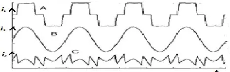
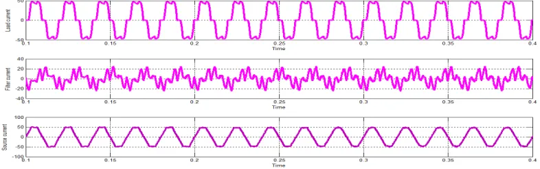
Fig.2: Wave forms of a) load current b) supply current c) compensating currents
The compensation current injected at PCC by the shunt APF should be
Ic = ILh (2)
The resulting source current is
After compensation the source current contains only the fundamental component of the nonlinear load current and thus free from harmonics. Shunt active power filter can reduce the harmonics in source current more effectively.
III.CONTROL STRATEGY
The control of SAPF mainly subjected to control algorithm used for the extraction of reference compensator currents to improve system performance. Various control strategies such as PQ, SRF, ISC Theories are described as follows
A.Instantaneous P-Q Theory
The Generalized Theory of the instantaneous Reactive power in Three-phase circuits” also Known as PQ Theory is based on the instantaneous values in three-phase power systems with or without neutral wire, and is valid for steady state or transient operation as well as for voltage and current waveforms [2]. The P-Q Theory consists of an algebraic Transformation (clarke Transformation) of three-phase voltages and currents in the a-b-c to α-β-0 Coordinates.
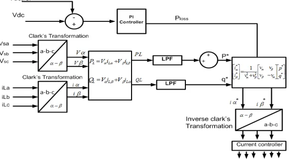
Fig 3: Control scheme using instantaneous P-Q Theory
The Clarke Transformation of three-phase generic voltages is given by
V
V
=3
2
2
3
2
1
2
3
2
1
0
1
c b aV
V
V
(4)
i
i
=3
2
2
3
2
1
2
3
2
1
0
1
cc cb cai
i
i
(5)
The instantaneous power is calculated as:
Finally, we can calculate reference current as:
i i i i i fc fb fa 2 3 2 1 2 3 2 1 0 1 3 2 * * *
(7)
The basic control diagram of instantaneous p-q theory in figure 3 shows the instantaneous voltages and line currents referred to the a,b,c axis phases are transformed into αβ0 stationary axis , or vice versa. They are stationary axis and should not be confused with the concepts of voltage or current phasors. The a, b and c axis are spatially shifted by 120° from each other while the α and β axis are orthogonal, and the α axis is parallel to the a axis. The direction of the β axis is chosen in such a way that if voltage or current spatial vectors on the abc coordinates rotate in the abc
sequence, they would rotate in the α-β sequence on the α-β coordinates.
B.Synchronous Reference frame theory
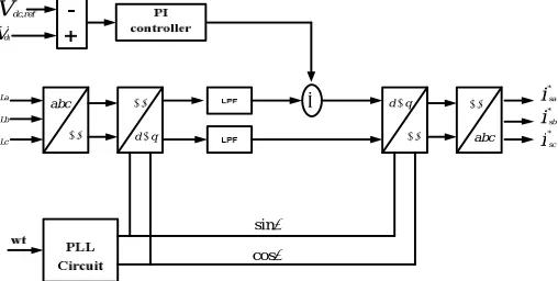
The time domain based synchronous reference frame theory is utilized to extract the reference current from the distorted line current. The SRF control strategy operates in steady-state as well as dynamic-state perfectly to control the active power line conditioner in real-time application [2].This Theory utilizes, Park’s Transformation which transforms three-phase a-b-c stationary coordinate system to the d-q-0 rotating coordinating system as dispicted in figure4. It
basically involves two transformation systems. The load currents are first converted in to α-β-0 Coordinates using clark’s Transformation and then in to d-q-0 rotating coordinating system using park’s Transformation. The transformation matrix is Expressed as
Lc Lb La q d i i i i i ) 3 2 cos( ) 3 2 sin( ) 3 2 cos( ) 3 2 sin( cos sin 3 2
(8)
Where θ is the angular displacement between a-axis and d-axis. The terminal voltages are given as an input to the PLL due to which the transformation of a-b-c to dq0 reference frame takes place. The switching loss of the inverter, which is added to the d-axis component of the current. Using filter, dc components of the current id and iq are filtered
out and by employing inverse transformation, reference compensator currents in stationary reference frame are produces for the control of SAPF[12].
cos sin abc abc
dq
q d i i i Lc Lb La i i i sc sb sa * * * Vdc
Vdc,ref
C.Instantaneous symmetrical component Theory
Instantaneous symmetrical component theory is used for both current and voltage compensation.The Technique was introduced by “Fortescue”. It is applied to resolve an unbalanced Three-phase system of voltages and currents into three-phase balanced systems of voltages and currents. The ISC can be used for the purpose of load balancing, Harmonic suppression, and power factor correction. In the symmetrical components theory there are two kinds of voltage components transformations. First one – direct transformation - is used to calculate symmetrical components having three unbalanced voltage phasors:
a a a a V V V 2 2 0 1 1 1 1 1 3
1
(9)
Second one - inverse transformation and is employed to calculate phasors containing certain amount of symmetrical components.
V
V
V
A
V
V
V
a
a
a
a
V
V
V
c b a 0 0 2 21
1
1
1
1
(10)Thus, the symmetrical component transformation matrixes A and A-1 are equal to:
a
a
a
a
A
2 21
1
1
1
1
(11)
a
a
a
a
A
2 2 11
1
1
1
1
3
1
(12)
The , , for phasor representation of zero, positive and negative sequence components of phase- neutral voltage in the phase-a respectively. The va,vb ,v c stands for phasor representation of voltages of phases a,b,c
respectively. According to Fortescue’s theory in balanced system only positive components exists. The negative and the zero components appear in the electrical system during voltage unbalance at fundamental frequency. However, it should be noted that in any three-phase three-wire system the sum of three instantaneous phase voltages or currents is zero. Therefore, the zero sequence components are not present. This feature greatly simplifies analysis of three-wire converter systems. Zero sequence components appears only during unbalance of three-phase, four-wire grounded system.
The symmetrical component theory originally defined for steady state analysis of 3-phase un-balanced systems. This transformation is the result of the multiplying the transformation matrix by the phasor representation of un-balanced 3-phase systems.
sa sb SC
sa
V
aV
a
V
V
23
1
3 2
j
a
a
“a” is a complex operation
sc sb sa sc sb saV
V
V
V
V
V
2
1
2
3
2
3
tan
)
(
1
(14)sc sb sa sc sb
V
V
V
V
V
2
1
2
3
2
3
tan
Where3
tan
, sa sb sc sc sb
V
V
V
V
V
2
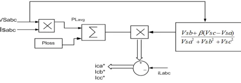
(15)Among the various control algorithms, this theory is most popularly used because of its simple and easy implemantation.Also it offers, precise results as compared to the other algorithms operating under the same load conditions. Here it is seen from the control technique depicted in figure5 that reference currents can be evaluated using the formulations given below.
Fig 5: Control diagram of ISC Theory, phases a and c are identical as phase b
2 2 2 *
(
)(
)
sc sb sa Loss Lavg sc sb sa La sa La cav
v
v
p
p
v
v
v
i
i
i
i
2 2 2 *(
)(
)
c sb sa Loss Lavg sa sc sb Lb sb Lb cbv
v
v
p
p
v
v
v
i
i
i
i
2 2 2 *
(
)(
)
sc sb sa Loss Lavg sc sa sc Lc sc Lc ccv
v
v
p
p
v
v
v
i
i
i
i
(16)
Where β =tanϕ/√3 ϕ is desired phase angle between supply voltages (vsa, vsb, vsc) and compensated source currents
(isa ,isb ,isc) , plavg is dc, or mean value of the load power and ploss is switching losses in the VSI. In ISCT Algorithm
provide better compensation, Low THD, and improve power factor.
IV. SYSTEM CONFIGURATION
A 3-ɸ, 415V, 50Hz supply fed Shunt Active Filter is developed in MATLAB/SIMULINK using Simpower System toolbox.
A. Design Parameters of Shunt Active Filter: The design of a three-phase three-wire SAPF includes the design of the VSC and its other passive components. The DSTATCOM includes a VSC, interfacing inductors, and a ripple filter. The design of the VSC includes the DC bus voltage level, the DC capacitance, and the rating of IGBTs.
The minimum dc bus voltage of VSC of SAPF should be greater than twice of the peak of the phase voltage of the system. The dc bus voltage is calculated as
m
v
v
LLdc
3 2 2
(17)
where, m is the modulation index and is considered as 1 and VLL is the ac line voltage of three phase source.
(ii) Selection of DC Bus Capacitor:
The value of the DC capacitor (Cdc) of the VSC of the SAPF depends on the instantaneous energy available to the
SAPF during transients. The principle of energy conservation is applied as
t aI V dc
dc
v
v
c
dc[( ) ( 1)] 3 ( )2
1 2 2
(18)
Where Vdc is the reference dc voltage and Vdc1 is the minimum voltage level of dc bus, a is the over loading factor
taken as 1.2, V is the phase voltage, I is the phase current and t is time by which the dc bus voltage is to be recovered (ii) Selection of an AC Inductor:
The selection of the AC inductance (Lr) of a VSC depends on the current ripple, switching frequency fs, and DC bus
voltage (VDC), and it is given as
Lr =√3mVdc/(12afsIcrpp) (19)
where m is the modulation index and a is the overloading factor.
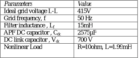
System Parameters:
Parameters Value
Ideal grid voltage L-L 415V
Grid frequency, f 50 Hz
Filter inductance , Lf 15mH
APF DC capacitor , Cdc 2575µF
DC link capacitor , Vdc 700 V
Nonlinear Load R=10ohm, L=1.99mH
V . PARTICAL SWARM OPTIMIZATION (PSO)
Particle swarm optimization (PSO) is a population based stochastic optimization technique developed by Dr. Eberhart and Dr. Kennedy in 1995, inspired by social behavior of bird flocking or fish schooling.PSO shares many similarities with evolutionary computation techniques such as Genetic Algorithms (GA). PSO technique is a population based computing technique. The idea behind this algorithm was the behavior of the swarm such as bird flock and fish schools. Here each represents ‘particle’ in the swarm and flock is the fitness function.
The particle position and velocity updating is given by equation
V = ωV + C rand[0,1] (p − X ) + C rand[0,1] (g − X ) (20)
where ‘ω’ is known as the inertia weight and Xi is the position of the ith particle. The parameters C1 and C2 are acceleration coefficients, where as rand() is a randomly generated value between 0 and 1.
The Position vector is given by
X = X + V (21) = Position Vector, = Velocity vector
P = Each Particle has even updated to their best encounter position G = Any particle has even updated to their best encounter position
This paper employs an objective function to minimize Total Harmonic Distortion (THD). The parameter values used for the particle swarm are given in the table.1.
Table 1: Parameters of PSO algorithm
VI. SIMULATION RESULTS
This section describes the Simulation of SAPF with all the above mentioned algorithms. The simulation models are developed and analyzed, compared graphically under balance source condition is given in the subsection as follows. A nonlinear load connected to ac system resulted in distorted source current and the total harmonic distortion is found to be 28.40%.
P-Q theory with classical PI-controller:
Shunt active power filter has been introduced into the system using P-Q theory and classical PI controller parameters Kp and Ki are determined by classical methods. The compensation source currents are obtained by using p-q theory is
as shown in below waveforms.
Fig:7 Wave forms of a) load current b) compensating current c) supply currents
P-Q theory with Optimized PI-controller
In this case PI-controller parameters are tuned by using particle swarm optimization (PSO) and the obtained wave forms are as below
Parameter PQ SRF ISCT Population Size 10 10 10 Number of Iterations 100 100 100
C1 1 2.5 2
Fig:8 Wave forms of a) load current b) compensating current c) supply currents
SRF theory with classical PI-controller:
Fig:9 Wave forms of a) load current b) compensating current c) supply currents
SRF theory with Optimized PI-controller
In SRF theory the PI-controller to regulate the dc bus voltage is tuned by using Particle swarm optimization (PSO) and the resulted waveforms are as shown below
Fig:10 Wave forms of a) load current b) compensating current c) supply currents
ISC theory with classical PI-controller:
Fig 11: Wave forms of a) load current b) compensating current c) supply currents
ISC theory with Optimized PI-controller
SAPF based on instantaneous symmetrical component theory is simulated by using tuned values of PI-controller parameters and the resulted waveforms are as below
Fig:12 Wave forms of a) load current b) compensating current c) supply currents
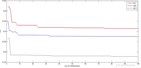
VII. COMPARITIVE STUDY
In this paper the performance of three control algorithms P-Q, SRF and ISC theories are compared. The performance of SAPF is improved with tuned parameters of PI-controller and it was observed that ISC theory results in less total harmonic distortion with unity power factor.
Control
Conventional PI PSO tuned PI
PF Kp Ki %THD Kp Ki %THD
PQ 0.25 1.55 4.33 0.004 1.50 3.0 0.8
SRF 0.025 0.14 3.64 1.823 1.99 2.75 0.95
ISC 1 0.5 2.09 0.320 0.92 1.7 1
VIII.CONCLUSION
A shunt active power filter has been simulated for power quality improvement with different control algorithms. The performance of various control techniques are compared and is found that Instantaneous symmetrical component theory results in improved power quality with desired power factor of unity rather than other control techniques. ISCT using PSO tuned PI is the best control algorithm which presented satisfactory performance and good robustness.
REFERENCES
[1]. Maravathu Nagarjuna, Prafulla Chandra Panda, “Power Quality Factor Improvement using Shunt Active Power Line Conditioner,” IEEE International Conference on Advanced Communication, Control & computing Technologies, May 2014
[2]. Power Quality problems and Mitigation Techniques By Bhim Singh, Ambrish Chandra, and Kamal AlHaddad, Wiley 2015, Hardcover, 582 pages, ISBN: 978-1-118-92205-7.
[3]. Robert D Henderson, Patrick J. Rose “Harmonics: The effect on power quality and transformer” IEEE Trans. Industry Applications, vol. 30, no.3, (1994):pp. 528-532.
[4]. Chen C. and Divan D.M., “Simple topologies for single-phase AC line conditioning” IEEE Trans. Industry Applications, vol. 30, (1994):pp. 606–612.
[5]. Vechiu, Ionel; Gurguiatu, Gelu; Rosu, Emil” Advanced active power conditioner to Improve power quality in microgrids”,-IPEC, 2010 Conference Proceedings Digit Object Identifier :10.1109/ IPECON.2010.5697021;Publication Year: 2010 , Page(s):728 –733
[6]. C.S.Lam,W.H.Choi, M.C.Wong, and Y.-D. Han, “Adaptive dc-link voltage-controlled hybrid active power filters for reactive power compensation,” IEEE Trans. Power Electron., vol.27, no. 4, pp. 1758–1772, Apr. 2012
[7]. H. Akagi and K. Isozaki, “A hybrid active filter for a three-phase 12-pulse diode rectifier Used as the front end of a medium-voltage motor drive,” IEEE Trans. Power Electron., vol. 27, no. 1, pp.69–77, Jan. 2012.
[8]. J. K. Phipps, J.P. Nelson, P. K. Sen, “Power Quality and Harmonic Distortion on Distribution Systems”, in IEEE Trans. on Ind. Appl., vol. 30, No 2, March/April 1994, pp. 176-184.
[9]. Roger C.Dugan, Mark F.Mc.Granaghan, Surya Santoso and H.Wayne Beaty, “Electrical power system quality” Mcgraw-Hill.
[10]. Amoli M. E. and Florence T., “Voltage, current harmonic content of a utility system-A summary of 1120 test measurements,” IEEE Trans. Power Delivery, vol. 5, (1990): pp. 1552–1557.
[11]. H. Akagi and K. Isozaki, “A hybrid active filter for a three-phase 12-pulse diode rectifier Used as the front end of a medium-voltage motor drive,” IEEE Trans. Power Electron.,vol. 27, no. 1, pp.69–77, Jan. 2012.
[12]. M.Sunitha, B. N .Kartheek, “Elimination of Harmonics Using Active Power Filter Based on DQ Reference Frame Theory,” International Journal of Engineering Trends And Technology, Vol. 4, Issue 4, pp. 781, April 2013.
BIOGRAPHY
Professor in Gudlavalleru engineering college, Krishna(DT), A.P, and India. His interested areas are in the field of electrical machines, power converters, and electrical drives.