Automatic USB Controlled Power Switch
Manish P 1, Praveen K Ravindran 1, Sandesh Varma E 1, Kiran K Kannan 1, Sanjay Lakshman 1,Vimi K Wilson2
U.G. Students, Department of Electrical and Electronics Engineering, Nehru College of Engineering and Research
Centre, Thrissur, Kerala, India1
Assistant Professor, Department of Electrical and Electronics Engineering, Nehru College of Engineering and Research
Centre, Thrissur, Kerala, India2
ABSTRACT: The main concept is to provide a circuit which uses the USB port of electronic devices as an automatic switch to control the input supply to that device. Energy wastage is one of the most severe problem faced nowadays. The wastage of energy from home appliances or electronic devices takes a major role in this problem. All electronic devices come with one or more USB port. The circuit uses these USB port to control the input supply. When TV or any other electronic devices is switched off using remote, its SMPS will consume a small amount of power which leads to the wastage of energy. This circuit gives a solution for such problem. Thus, as soon as the device get switched off using remote, the entire supply to the device get turned off and saves energy. The device can again be switched on by pressing the push button in the circuit. The circuit protects the electronic devices from harmful initial surges.
KEYWORDS:USB Port, Transistor, Relay, Output Supply.
I.INTRODUCTION
II.BLOCK DIAGRAM
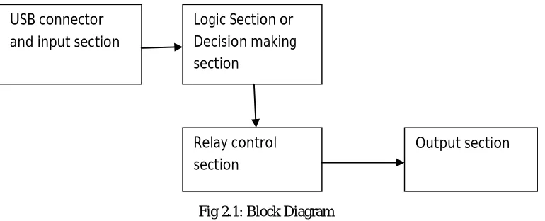
Figure 2.1 shows the block diagram of the automatic USB controlled power switch. The various components in the system are described below.
Fig 2.1: Block Diagram
The blocks in the block diagram are USB connector and Input Section, Logic Section or Decision Making Section, Relay Control Section and Output section. The USB connector and input section mainly consist of a USB port (male) which receives the incoming 5V from the USB port (female) of electronics devices like TV, Set Top Box, which is given as the input to the circuit. The Logic Section or Decision Making Section consist of a Transistor which will control the relay section. The transistor make the relay ON when it detects the 5V at its base. When there is an absence of 5V in its base, it will make the relay to OFF state. The Relay Control Section holds a 12V relay which act as a switch between the 230V supply. 230V AC mains power supply connector is connected between N/O contacts of the Relay and Neutral line. The Output Section has a plug socket to which the electronic devices are connected. The Relay is initially at OFF state and there is no output in the output section so there is an absence of 5V coming from the devices which leads the Transistor to make the Relay in OFF state. In order to make the Relay ON, a push button is used to give a 5V supply to the base of the Transistor. When the switch is pressed, a 5V supply is given to base of the Transistor which will make the Relay to ON state and output (230V AC Supply) is received at the output section. Power supply to the electronic devices like TV, S.T.B, D.V.D player etc. are taken from this output section. As soon as the device is switched on, a 5V supply will be received at the base of Transistor from the USB port through the USB connector. This will lead the transistor to make Relay to continue in ON state. When the device is switched off using remote the 5V from the USB port of device is disconnected, and leads the transistor to make the Relay to OFF state and output (230V AC) to the devices get disconnected thus saving the energy.
Hardware description
Transformer
A transformer is an electrical device that transfers electrical energy between two or more circuits through electromagnetic induction. Transformers convert AC voltage from one level to another level with a little loss of power. Transformer has mainly two coils, primary and secondary. A transformer operates on the principals of “electromagnetic induction”, in the form of mutual induction. The transformer used here is a step-down transformer so that it can be directly convert 230v AC to 12v AC.
USB connector and input section
Logic Section or Decision making section
Relay control section
Relay
Relays are components which allow low power circuit to operate high current application circuits. It is an electrically operated switch and is used where it is necessary to control a circuit by a low-power signal with complete electrical isolation between control and controlled circuits, or where several circuits must be controlled by one signal. The relay used here is an electromagnetic type which operates in 12v.
USB port
USB (Universal Serial Bus) defines the cables connectors and communication protocols used in a bus for connection, communication and power supply between computers and electronic devices. The figure 3.5 shows the male USB port.
USB was designed to standardize the connection of computer and electronic peripherals. The terminals of USB port are
V+
Data+
Data-
GND
Transistor BC547
BC547 is an NPN Bi-polar Junction Transistor (BJT). A transistor, stands for transfer of resistance, is commonly used to amplify current. A small current at its base controls a larger current at collector & emitter terminals. Together with other electronic components, such as resistors, coils and capacitors, it can be used as the active component for switches and amplifiers. Like all other NPN transistors, this type has an emitter terminal, a base and a collector terminal. In a typical configuration, the current flowing from the base to the emitter controls the collector current. BC547 is mainly used for amplification and switching purposes. It has a maximum current gain of 800. The figure 3.6 shows a BC547 Transistor and figure 3.7 shows the pin diagram of BC547 Transistor.
Bridge rectifier
A single phase rectifier uses four individual rectifying diodes connected in a closed loop bridge configuration to produce the desired output. The main advantage of this bridge circuit is that it does not require a special center tapped transformer, thereby reducing its size and cost. The single secondary winding is connected to one side of the diode bridge network and the load to the other side. The bridge rectifier converts the 12V AC to 12V DC which is the required power supply for the circuit.
Push button
A push-button (also spelled pushbutton) or simply button is a simple switch mechanism for controlling some aspect of a machine or a process. Buttons are typically made out of hard material, usually plastic or metal. The surface is usually flat or shaped to accommodate the human finger or hand, so as to be easily depressed or pushed. Buttons are most often biased switches, though even many un-biased buttons (due to their physical nature) require a spring to return to their un-pushed state
.
III. CIRCUIT DIAGRAM
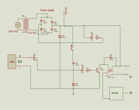
Fig 3.1: Circuit diagram of automatic USB controlled power switch
Circuit Diagram Description
Figure 3.1 shows the complete circuit diagram of automatic USB controlled power switch with sufficient rating as we used. The main circuit provides two functions, rectification and logical operation. Therefore the circuit is divided into two.
The two circuits are
Power supply circuit
Logic circuit
Power supply circuit
Fig 3.2:Power Supply Circuit
Figure 3.2 shows the power supply circuit. The circuit uses standard power supply comprising of a step down transformer from 220V to 12V and four diodes forming a bridge rectifier that delivers pulsating DC which is then filtered by an electrolytic capacitor of about 1000µF. The 230V AC coming from the supply is converted into 12V DC by using this circuit. The transformer used has 230V at its primary and delivers 12V at secondary. The capacitor used in the power supply circuit will reduce the ripples in the dc supply. This circuit provides 12V dc supply to the logical circuit. The diodes used are IN4007, which will permit the current flow only in one direction. Here 4 diodes are used in bridge rectifier for converting the alternative current to direct current and provides an effective supply for the logical device.
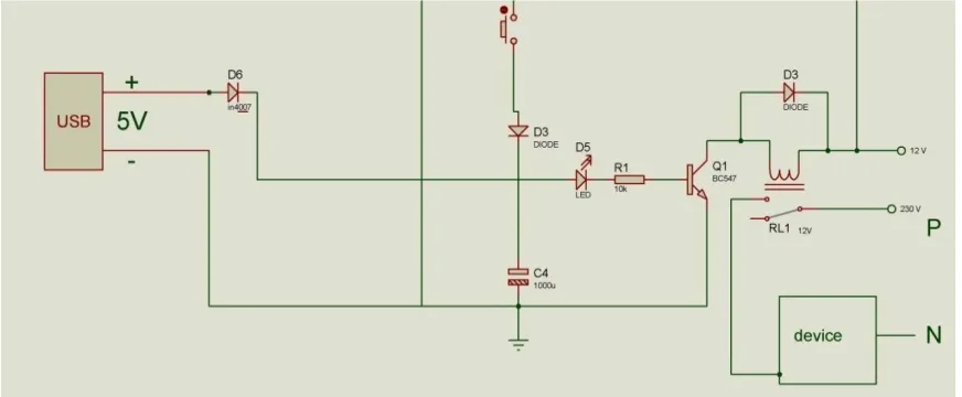
Figure 3.3 shows the logic circuit. This is the circuit comprising main operation. The 5V USB input shown is the female port from the appliance connected, the diode D6 is kept to prevent the reverse current into the appliance. When a 5V is present which is connected to the base of the transistor BC547 turns ON the transistor which energizes the coil of electromechanical relay and the relay which normally open starts conducting. When the relay starts conducting a 230V supply output is given to the device (load).Here initially 5V is not present because load connected is in OFF condition. Therefore, at starting stage a switch is kept to give a pulse in order for the transistor to conduct.
Connections
The bridge rectifier circuit is connected directly to the supply which gives an output of 12V DC. A LED along with a resistor is connected in the load side of rectifier to indicate the power supply. A push button is connected to the positive terminal of 12V DC supply to give a 5V supply to the base of transistor BC547 at the initial stage. A resistor of 10K is also connected between the push button and transistor to give a 5V supply. The coil terminals of the 12V relay is connected between the positive terminal of 12V DC and the collector of transistor BC547. Phase or Neutral of 230V AC supply is given to the COMMON terminal of relay. Phase or Neutral of the device with USB port is connected to the normally closed terminal of relay. The other terminal of 230V AC supply (Neutral or Phase) is connected directly to corresponding terminal of device. Transistor BC547 is insisted to control the switching of relay. The V+ terminal of USB port is connected to the base of transistor BC547 through LED, resistor and a capacitor of 1000µF. The GND terminal of USB port is connected to the emitter of transistor and the negative point of capacitor. A diode IN4007 is connected between +V terminal of USB port and base of transistor, and between the coil connection of relay in order to prevent the flow of reverse current. The USB port of circuit is connected to the USB port of the device. When the supply is given, the relay is in OFF state, the push button is pressed which stores the charge in capacitor 1000µF which starts to discharge by giving a 5V supply to the base of transistor which makes the relay ON and the device get supply which makes the device ON. This results in giving a 5V supply from the USB port of the device to the base of transistor which allows the relay to continue in ON state. When the device is switched off using remote the 5V from USB is disconnected which makes the relay OFF which cut off the supply to the device.
IV. EXPERIMENTAL RESULTS
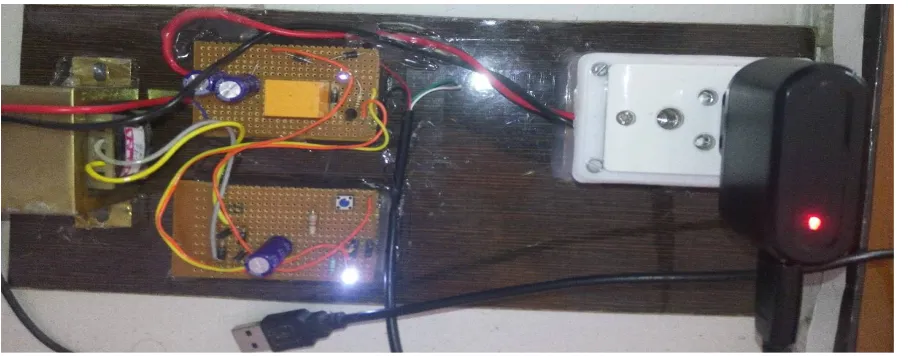
Figure 4.1 represent the completed system of automatic USB controlled power switch. It is demonstrated as connecting a USB charger with a red LED to indicate the output supply.
V.CONCLUSION
To develop an efficient circuit in a simpler manner, it has been decided to do a project on Automatic USB Controlled Power Switch. Even though this circuit consists of simpler electronic components it can make great changes in electricity consumption. The main application of the circuit is in appliances with USB port. It is developed in order to help save energy during standby mode.
REFERENCES
[1] Ajith Kumar, “Automatic USB-controlled Power Switch”, Electronics for You, pp.114-115, November 2015.
[2] Shuixiang Li,”Development of Data Communication System Applied to Electrical Instruments Based on USB Interface” , International Conference , IEEE, Vol 4, pp. 424-428,2010.
[3] Laurence Mcgarry, “Standby Power Challenge”, International IEEE Conference on the Asian Green Electronics, pp. 56-62, 2004.
[4] A.I. Maswood and Z.K. Yoong, “Digital burst technique in the standby operation of a power supply”, IEEE IAS Annual Meeting, Industry Applications Conference, pp. 1661-1668, 1999.
[5] En Cheng,” System Design of DMB-T-Receiver Based on the USB Interface”,2nd International Conference IEEE,vol 1,pp. 333-335, 2009.
BIOGRAPHY
Ms. Vimi K Wilson, Assistant professor, has obtained her B.Tech degree from Vidya Academy of Science and Technology and M.Tech degree from Nehru College of Engineering and Research Centre in 2009 and 2014 respectively. She is currently serving as Assistant professor in Nehru College of Engineering and Research Centre, Thrissur, Kerala, India. She has 2+year of teaching experience to both undergraduate and
postgraduate students.
Manish P, UG Student, Dept. of EEE, Nehru College of Engineering and Research Centre,Thrissur,Kerala,India.
Praveen K Ravindran, UG Student, Dept. of EEE, Nehru College of Engineering and Research Centre, Thrissur, Kerala, India.
Sandesh Varma, UG Student, Dept. of EEE, Nehru College of Engineering and Research Centre, Thrissur, Kerala, India.
Kiran K Kannan, UG Student, Dept. of EEE, Nehru College of Engineering and Research Centre, Thrissur, Kerala, India.