Modelling and Analysis of Corrugated Sheet
Metal Bending Process
P.Devendran1, R.Sambasivam2
Assistant Professor, Department of Mechatronics Engineering, SNS College of Technology, Tamilnadu, India1 Assistant Professor, Department of Mechatronics Engineering, SNS College of Technology, Tamilnadu, India2
ABSTRACT: Sheet metal forming is one of the most common metal forming processes. In Sheet Metal industries accuracy plays a vital role. One of the major causes for the fabrication of inconsistent sheet metal part is springback which is also defined as the recovery of elastic strain after the tooling is expelled. Spring back of sheet metal parts after forming causes deviation from the designed target shape and also produces downstream quality problems and assembly difficulties. So the crucial thing in the manufacturing is the problem of controlling springback effec. The aim of this project is to analysis and reduces the effect of springback in sheet metal forming process of corrugated sheets. First the finite element analysis (FEA) of corrugated sheets is created using HYPERFORM by considering factor such as material property, sheet thickness, tooling geometry and process parameters. Here the numerical data which is obtained from finite element analysis are feed as the teaching data read for training the neural network by means of back propagation algorithm. Thus with Artificial Neural Network (ANN), the results of spring back effect for various combinations of sheet thickness, material & punch force are obtained and discussed.
KEYWORDS:Springback Effect, HyperForm, Corrugated Bending, Artificial Neural Network.
I. INTRODUCTION
Sheet metal forming is the process to change geometrical characteristics of the sheet metal without removing the any material when the forces applied on it. The applied force on the metal beyond its maximum yield point which causes the material to deform plastically but it couldn’t be fracture. During the bending operation inside of the neutral plane is compressed, while the metal on the outside of the neutral plane is stretched. In bending process increase the strength of the material. The simple bending terminology figure 1 shown below. Sheet metal forming processes include the processes like Bending, Roll forming, Spinning, Deep Drawing and Stretch forming. Normally, Single bending operations are used in the industrial applications for analyzing springback effect in sheet metal component. The current trial-and-error method of testing and controlling for springback effect is costly, time consuming, and remains as an obstacle in achieving shorter design production cycles when compared with corrugated bending operation. The forming of sheet metal into a drawing, corrugated alternate ridges and grooves with a specially shaped punch and die as shown in figure 2. A corrugated metal revetment is also made from some type of roll formed mill. Typically heavy-gauge steels like 16-gauge or 18-gauge can b used in the forming process.
1 2 1 2 2 2 0 0 0 h R h R b R h R K f f f s
4
3
01
3 0 0
Eh
R
Eh
R
R
R
f
Therefore, our present work focuses on springback effect in corrugated bending operation. We use the same factors such as sheet thickness, punch radius, bend allowance, tooling geometry and process parameters. These factors are taken as input parameter for modeling in Hyper-form and also analyzed the springback effect simulation in the same FEA tool.
II. MATHEMATICALMODELINGOFSHEETMETALBENDING
A.
SPRINGBACK EFFECTSpringback is the dimensional change of the formed part after the pressure of the forming tool has been released. The elastic recovery is obtained as the results when the strain is removed. When the load is released, the total strain is reduced owing to the elastic recovery. The elastic recovery, and therefore the springback, will be greater the higher the yield stress, the lower the elastic modulus, and the greater the plastic strain. High strength steels are the increased levels of springback due to the high yield strength of the steel and the variation in springback due to the material anisotropy. High strength steels by definition have larger material yield stresses, require higher forces to form parts and tend to be anisotropic in nature. These factors significantly affect the springback behavior of parts stamped from these steels. Springback control is one of the key concerns of the sheet metal forming industry. The current trial-and-error method of testing and controlling for springback is costly, time consuming, and remains as an obstacle in achieving shorter design and production cycles. Furthermore, unavoidable variations in material and process parameters, which lead to springback uncertainty, require active process control in order to produce consistent parts.
During forming process, elastic stress gradients across the sheet metal bending area builds up which leads to accumulation of residual stresses. Due to the accumulation of residual stresses cause the material to return back some angle after the load is removed. After the resultant deviations, the rework is needed for assembling the component into the profile, it require manual adjustment. Meanwhile the components which do not fit in the final assembly need to undergo the additional shimming and assembly time.
In this paper, it clearly shows the set up procedure for performing a springback analysis for Radioss. The part shape and stress and strain states at the end of a simple draw forming operation are the inputs to setup. Appropriate material and section properties are assigned to the blank component. Fixture constraints are applied to the part to eliminate rigid body modes. Springback is encountered in all forming process but it is most easily recognized and studied in bending. The radius of curvature before release of load R is smaller than the radius after release of the load R. But the bending allowance is same before and after bending. So
f f h R h R
B
2 2 0 0
Thus the springback ratio (Ks),
0
f sK
is given by,
B. PERCENTAGE OF THINNING:
Percentage of thinning is another one main parameter in the sheet metal bending process. After the bending the thickness of the blank is changed. The change in thickness causes the fracture and not comfortable to use. Thinning (%) is as follows
Where, t0- Initial thickness t- Final thickness
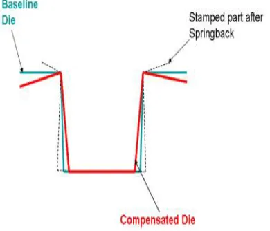
C. DIE COMPENSATION:
Die compensation is used to reduce the deviation of the stamped part from its design target geometry as a result of springback. The original die geometry is morphed by applying a displacement field in a direction opposite to the springback of the sheet metal. Special care is taken to avoid creating undercuts to negative drafts as a result of the compensation. The compensation of die shown in figure 3
Figure 3 Die Compensation
III. DESIGN&MODELLING
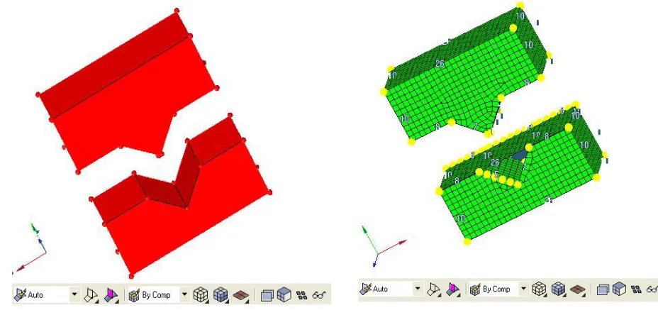
The Pro E model of punch and die is import in Hyperform-Radioss software. From the imported part, the reference point is set. Based on the reference point a new shell part is created. And the total part is meshed by using Hypermesh as shown in the figure 4 as follows
A. HYPERFORM
HyperForm One-Step and incremental analyses are tightly integrated with Hyper Morph and Hyper Study, which allows the optimization of forming tools and process parameters using a highly automated approach.
Figure 4 Example Model for HyperForm & HyperMesh
B. ALTAIR HYPERMESH
Altair HyperMesh is a high-performance finite-element pre-processor for popular finite-element solvers. It allows engineers to analyze product design performance in a highly interactive and visual environment.
HyperMesh’s user interface is easy to learn and supports a number of CAD geometry and finite-element model file formats, thereby increasing interoperability and efficiency. Advanced functionality within HyperMesh allows users to efficiently manipulate geometry and mesh highly complex models.
These functionalities include extensive meshing and model control, morphing technology to update existing meshes to new design proposals and automatic mid-surface generation for complex designs with varying wall thicknesses.
Solid geometry enhances tetra-meshing and hexa-meshing by reducing interactive modeling times, while batch meshing enables large scale meshing of parts with no manual clean-up and minimal user input.
C. RADIOSS
IV.SIMULATION
A. INPUT PARAMETERS
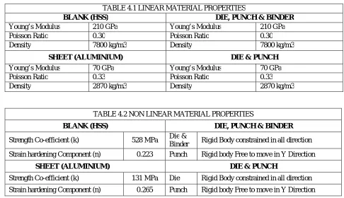
The blank is made of mild steel. The material is modeled as an elastic-plastic material with isotropic elasticity, using the Hill anisotropic yield criterion for the plasticity. The parameter of Linear Material Properties and Non- Linear Material properties are as follows
TABLE 4.1 LINEAR MATERIAL PROPERTIES
BLANK (HSS) DIE, PUNCH & BINDER
Young’s Modulus 210 GPa Young’s Modulus 210 GPa
Poisson Ratio 0.30 Poisson Ratio 0.30
Density 7800 kg/m3 Density 7800 kg/m3
SHEET (ALUMINIUM) DIE & PUNCH
Young’s Modulus 70 GPa Young’s Modulus 70 GPa
Poisson Ratio 0.33 Poisson Ratio 0.33
Density 2870 kg/m3 Density 2870 kg/m3
TABLE 4.2 NON LINEAR MATERIAL PROPERTIES
BLANK (HSS) DIE, PUNCH & BINDER
Strength Co-efficient (k) 528 MPa Die &
Binder Rigid Body constrained in all direction Strain hardening Component (n) 0.223 Punch Rigid body Free to move in Y Direction
SHEET (ALUMINIUM) DIE & PUNCH
Strength Co-efficient (k) 131 MPa Die Rigid Body constrained in all direction Strain hardening Component (n) 0.265 Punch Rigid body Free to move in Y Direction
B. SIMULATION USING PARAMETERS
HyperForm is a unique finite element based sheet metal forming simulation software solution. HyperForm combines an extremely fast one-step solver and incremental forming solution with the customized geometry manipulation and mesh generation capabilities of HyperMesh. HyperForm provides engineers, at any stage of product design, with quick, valuable, and reliable information, reducing the overall product cycle. Hyper Form’s die module takes a giant leap in bringing the product designer closer to manufacturing by enabling engineers to create and analyze conceptual die designs in order to generate an optimized die.
Die concepts can then be read into any CAD system as a starting block for the actual die build. Integrated with HyperView, HyperForm can export data in H3D format allowing results to be visualized using HyperView Player with any web browser.
Figure 5 Percentage of thinning at frame 9 Figure 6 Percentage of thinning at frame 10
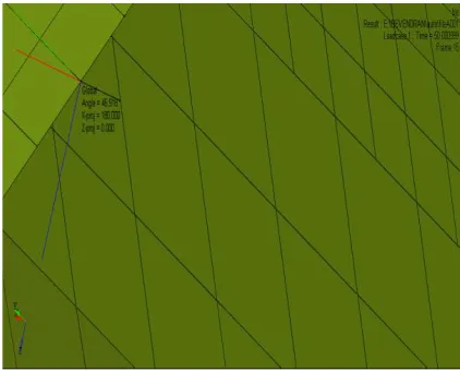
From figure 7, the red mark represents the maximum stress distribution.
Figure 7 Stress in 10th frame
The percentage of thinning of the material is low(minimum) and shows the maximum springback angle for the same punch velocity 2000 m/s as presented in figure 8 and 9.
The springback can be reduced by increasing the punch velocity ranging from 2000 m/s to 5000 m/s. The usage of binder acts as a support of the sheet or blank. These binders can be used to decrease the stress distribution and also to reduce the springback.
V.CONCLUSION
Previous researchers have concentrated only on springback effect using simple bending and the results are validated with experimental and mathematical calculations. Most of the industrial applications using corrugated sheet metal bending. The present work analyses the springback effect of corrugated bending using HYPERFORM- RADIOSS. It concludes that,
Spring back effect in corrugated bending changed with varying thickness of the material.
The binders can be used to reduce springback effect and also helps to distribute the stress evenly
REFERENCES
[1] Garcia-Romeu.M.L, Ciurana.J, Ferrer.I (2007), ‘Springback determination of sheet metals in an air bending process based on an experimental work’, Journal of Materials Processing Technology, Vol.191, pp.174-177.
[2] Ihab Ragai, Duraid Lazim, James A. Nemes (2005), ‘Anisotropy and springback in draw-bending of stainless steel 410 experimental and numerical study’, Journal of Materials Processing Technology, Vol.166, pp.116–127.
[3] I-Nan Chou, Chinghua Hung (1993), ‘Finite element analysis and optimization on springback reduction’, International Journal of Machine Tools & Manufacture, Vol.39, pp.517-536.
[4] Joachim.L, Grenestedt, Jack Reany (2007), ‘Wrinkling of corrugated skin sandwich panels’, Composites: Part A, Vol.38, pp.576–589.
[5] Jyhwen Wang, Suhas Vermab, Richard Alexander.B, Jenn-Terng Gauc (2008), ‘Springback control of sheet metal air bending process’, Journal of Manufacturing Processes, Vol.10, pp.21-27.
[6] Kazeminezhad.M, Hosseini.E (2010), ‘Optimum groove pressing die design to achieve desirable severely plastic deformed sheets’, Materials and Design, Vol.31, pp.94–103.
[7] Moon.Y.H, Kang.S.S, Cho. J.R, Kim. T.G (2003), ‘Effect of tool temperature on the reduction of the springback of aluminum sheets’, Journal of Materials Processing Technology, Vol.132, pp.365–368.
[8] Ozgur tekaslan Ulvi Seker, Ahmet Ozdemir (2006), ‘Determining springback amount of steel sheet metal has 0.5 mm thickness in bending dies’, Materials and Design, Vol.27, pp.251–258.
[9] Panthi.S.K, N. Ramakrishnan, Meraj Ahmed , Shambhavi S. Singh, M.D. Goel (2010), ‘Finite Element Analysis of sheet metal bending process to predict the springback’, Materials and Design, Vol.31, pp.657-662.
[10] Sergei Alexandrov, Yeong-Maw Hwang (2009), ‘The bending moment and springback in pure bending of anisotropic sheets’, International Journal of Solids and Structures, Vol.46, pp.4361–4368.
[11] Shirdel.A, Khajeh.A, Moshksar.M.M (2010), ‘Experimental and finite element investigation of semi-constrained groove pressing process’, Materials and Design, Vol.31, pp.946–950.
[12] Wei Gan, Wagoner.R.H (2004), ‘Die design method for sheet springback’, International Journal of Mechanical Sciences, Vol.46, pp.1097–1113. [13] Yang.Q, Ghosh.A.K (2006), ‘Production of ultrafine-grain microstructure in Mg alloy by alternate biaxial reverse corrugation’, Acta Materialia,
Vol.54, pp.5147–5158.
[14] Zafer Tekiner (2004), ‘An experimental study on the examination of springback of sheet metals with several thicknesses and properties in bending dies’, Journal of Materials Processing Technology, Vol.145, pp.109–117.