Modelling and Structural Analysis of Disc
plate with Different Materials by Using
ANSYS Software
[1]
K.Lakshmi kala, [2]Dr.T.Hari Prasad [1]
Assistant Professor, Sree vidyanikethan Engineering college, Tirupati, India
[2]
Professor, Sree vidyanikethan Engineering college, Tirupati, India
ABSTRACT: The disc brake is a wheel brake by which rotation of the wheel slows by the friction caused by compressing brake pads against a disc brake with a set of calipers. Usually cast iron disc brake is used, but the disc brake may in some cases be made of composites such as reinforced carbon– carbon or ceramic matrix composites. The present paper deals with the analysis of Disc rotor of a Bajaj pulsar150 DTSi bike. In general the Disc brake is made of Cast iron, for investigating the effect of strength variations on the predicted stress distributions,it has been selected. For the same disc rotor instead of Cast iron, Aluminum alloy material is selected and analyses. The model of Disc brake is developed by using Solid modeling software solid works. Further Static Analysis is done by using ANSYS Workbench. The results obtained from the static structural analysis of disc plate like Von-Mises stress, Von-Mises strain, total deformation, the grey cast iron gives better results when compared to aluminum alloy.
KEYWORDS: ANSYS Work Bench , Disc Plate, Finite Element Analysis, Solid Works.
1.INTRODUCTION
A Brake is a device by means of which artificial frictional resistance is applied to moving machine member, in order tostop the motion of a machine. To stop the wheel, friction material in the form of brake pads, mounted on a device called a brake caliper, is forced mechanically, hydraulically, pneumatically or electromagnetically against both sides of the disc. Friction causes the disc and attached wheel to slow or stop. Brakes convert motion to heat, and if the brakes get too hot, causes less efficient (brake fade). The disc brake is a wheel brake which slows rotation of the wheel by the friction caused by pushing brake pads against a brake disc with a set of calipers. Disc brake consists of a disc bolted to the wheel hub and a stationary housing called caliper. The caliper is connected to a stationary part of the vehicle like the axle casing or the stub axle as is cast in two parts each part containing a piston. To improve the braking efficiency usage of other materials instead of castiron is investigating. The brake disc (or rotor in American English) is usually made of cast iron. This is connected to the wheel and/or the axle.
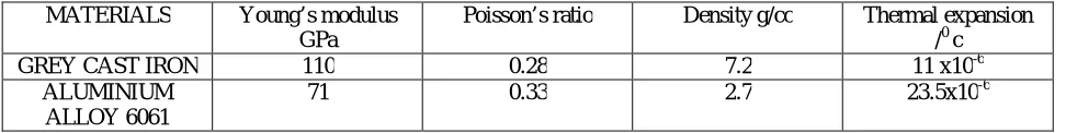
In this paper materials used for analysis of disc brake are Grey cast iron and Aluminium alloy 6061 and their properties are tabulated in table11.
Table 1:Materials Used For Disc Brake
MATERIALS Young’s modulus GPa
Poisson’s ratio Density g/cc Thermal expansion /0 c
GREY CAST IRON 110 0.28 7.2 11 x10-6
ALUMINIUM ALLOY 6061
II.MODELLING PULSUR150 DTSi DISC BRAKE
The photographic view of pulsur150 disc brake is as shown in the figure.
Fig. 1 Photographic view of Pulsur150 DTSi disc brake
Modelling of pulsur150 disc brake is done using solidworks software. SOLIDWORKS is solid modeling software that runs on Microsoft Windows and has been produced by assault system, SOLIDWORKS Corp., since 1997.
The different views of disc brake in the solidworks modeling is shown in the figure below.
Fig.3 Different views of disc brake
III.ANALYSIS OF PULSUR150 DISC BRAKE
ANSYS provides a cost-effective way to explore the performance of products or processes in a virtual environment. This type of product development is termed virtual prototyping. With virtual prototyping techniques, users can iterate various scenarios to optimize the product long before the manufacturing is started. This enables a reduction in the level of risk, and in the cost of ineffective designs. The multifaceted nature of ANSYS also provides a means to ensure that users are able to see the effect of a design on the whole behavior of the product, be it electromagnetic, thermal, mechanical etc.
FEA procedure flow chart is shown below:
Fig.4 Flowchart for FEA analysis
IV. RESULT AND ANALYSIS
Static Structural Analysis Of Disc Plate For Cast Iron And Alumium Alloy 6061 Geometric Modeling
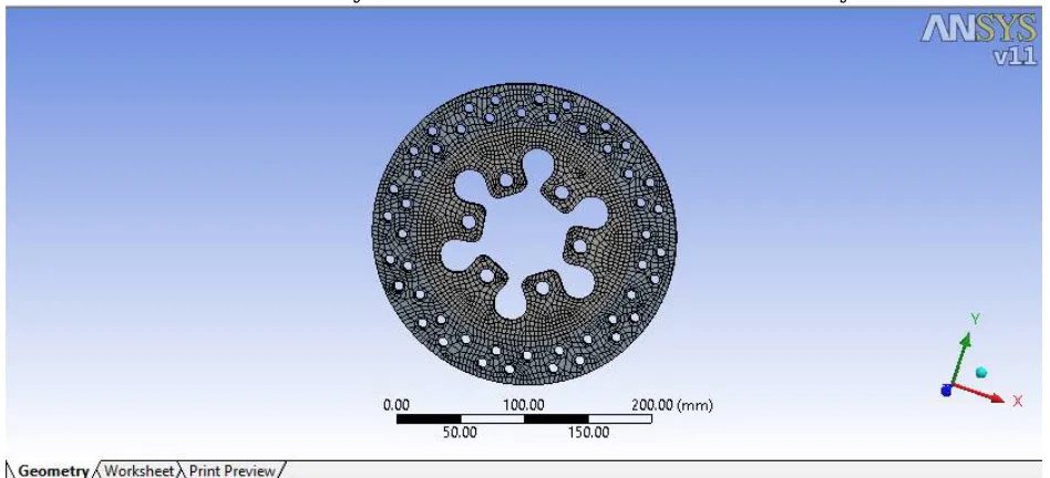
Finite Element Model (meshing)
Define the modeling Environment
Perform analysis
I. For Cast Iron:
A.Von-Mises stress
Fig.6Von-Mises stress for grey cast iron
B.Von-Mises strain
C.Total Deformation
Fig.8 Total deformation for grey cast iron
II. For Aluminium alloy 6061:
B.Von-Mises strain
Fig.9 Von-Mises strain for Aluminium alloy
C.Total Deformation
Fig.10 Total deformation for Aluminium alloy
Table 2:Results tabulated:
Material Von-Mises
Stress (MPa)
Von-Mises Strain (mm/mm)
Total Deformation (mm)
Grey CastIron 6.2243 5.6585x10⁻⁵ 0.00080765
AluminiumAlloy 6061 6.4201 9.0424x10⁻⁵ 0.00013664
V.CONCLUSION
By the comparison of various results obtained from the static structural analysis of disc plate like Von-Mises stress, Von-Mises strain, total deformation and mass, the Grey cast iron gives better results when compared to Aluminium alloy. For further scope, analysis for different materials can be made to give better performance
.
REFERENCES
1. V. M. Thilak , R. Krishnara Deepan & R.Palani ,“Transient ThermalAnd Structural Analysis Of The Rotor Disc Of Disc Brake”, InternationalJournal Of Scientific & Engineering Research Volume 2, Issue 8,August-2011 ISSN 2229-551.
2. Vignesh Shanbhag, Vikram Singh, Rathod Abhik And Baskar P,” Modeling And Squeal Analysis Of Brake Disc Rotor Using Ansys”, International Journal Of Mechanical Engineering & Robotics Research Vol. 3, No. 3, July 2014 ISSN 2278 – 0149.
3. Swapnil Umale ,Dheeraj Varma,” disc Brake Rotor Selection Through Finite Element Analysis”, International Journal Of Recent Trends In Engineering & Research (IJRTER)Volume 02, Issue 4; April - 2016 [ISSN: 2455-1457].
4. Swapnil R. Abhang, D.P.Bhaskar,”Design And Analysis Of Disc Brake”,international journal of engineering trends and technology (IJETT) – volume 8 number 4- feb 2014.
5. Atul sharma and M.L. Aggarwal,” Deflection And Stress Analysis Of Brake Disc Using Finite Element Method”, Proceedings Of The National Conference On Trends And Advances In Mechanical Engineering, YMCAUniversity Of Science & Technology, Faridabad, Haryana, Oct 19-20, 2012.
6. Er. N. B. Shinde, Prof. B.R. Borkar,” C.A.D. & F.E.M. Analysis Of Disc Brake System” International Journal Of Engineering And Computer Science ISSN:2319-7242 Volume 4 Issue 3 March 2015.
7. Viraj Para1, Kunal Naik, Prof A. D. Dhale,” Structural and Thermal Analysis of Brake Disc”, International Journal of Engineering Development and Research,2014, Volume 2, Issue 2 | ISSN: 2321-9939.
8. Floquet, A. And Dubourg, M.-C. Non Axis Symmetric Effects For Three Dimensional Analyses Of A Brake, Asme J. Tribology, Vol. 116, Page 401-407, (1994).
9. Daniel Das.A, Christo Reegan Raj.V, Preethy.S, Ramya Bharani.G “Structural and Thermal Analysis of DiscBrake in Automobiles” at International Journal of Latest Trends in Engineering and Technology (IJLTET) ISSN:2278-621X Vol. 2 Issue 3 May 2013.
10. S. M. Kim, A Study On Thermal Analysis In Ventilated Brake By Fem, Journal Of The Korean Society Of Machine Tool. International Journal Of Scientific & Engineering Research Volume 2 , Issue 8, August-2011.
11. Dr. Ramesha, Santhosh Kumar and Bharath Shekar, “Temperature Distribution Analysis of Aluminum Composite and Cast Iron BrakeDrum Using Ansys”, ‘International Journal of Emerging trends in Engineering and Development’, 2012, Vol. 3, Issn 2249-6149, pp 281-292. 12. G. Babukanth and M. Vimal Teja “Transient Analysis of Disk Brake By using Ansys Software” International