Design and Analysis of Storage Tank
Visal B 1, Sibin B 2
P.G. Student, Department of Mechanical Engineering, SNGCE, Kadayiruppu, Kerala, India1 Assistant Professor, Department of Mechanical Engineering, SNGCE, Kadayiruppu, Kerala, India 2
ABSTRACT: Storage tanks are containers that hold liquids, compressed gases (gas tank) or mediums used for the short or long-term storage. Most storage tanks are designed according to American Petroleum Institute API-650 specification. These tanks can have different sizes, ranging from 2 to 60 m diameter or more. Here the primary consideration was given to the safety of tank under various circumstances. The framework of this project was to design a storage tank with the following specifications and it’s analyse;
Height = 12m, diameter = 8m, density of oil = 860 kg/m3.
A systematic investigation have done in terms of various design procedures for storage tank and here the design was done in Variable Design Point Method.
The Finite Element Analysis of storage tank was done using ANSYS software. The sloshing effect on storage tank was mainly considered in this project. The static and wind load analysis has also been done using ANSYS.
KEYWORDS: API-650, Finite Element Analysis, ANSYS, Sloshing, Wind load.
I. INTRODUCTION
Storage tanks are containers that hold liquids, compressed gases (gas tank) or mediums used for the short- or long-term storage of heat or cold. The long-term can be used for reservoirs (artificial lakes and ponds), and for manufactured containers.
Storage tanks operate under no (or very little) pressure, distinguishing them from pressure vessels. Storage tanks are often cylindrical in shape, perpendicular to the ground with flat bottoms, and a fixed or floating roof. There are usually many environmental regulations applied to the design and operation of storage tanks, often depending on the nature of the fluid contained within. Above ground storage tanks (AST) differ from underground storage tanks (UST) in the kinds of regulations that are applied.
There are three methods allowed by API 650 to determine the required plate thickness of the shell. The first method is the one-foot-method (1FM) which is based on the ‘‘membrane theory’’. The required shell plate thickness for each shell course is calculated using the circumferential stress at a point 0.3 m (1-ft) above the lower horizontal weld seam of the shell course due to hydrostatic pressure of the stored liquid. The reasoning behind this assumption is that the tank bottom plates provide restraint to reduce circumferential stress due to hydrostatic pressure at the bottom 0.3 m (1-ft) of the lowest shell course. Similarly, a shell course other than the lowest shell course, has generally thicker shell plates below. The plate below provides some restraint at the lower portion of the shell course in consideration. The 1FM is used successfully for the majority of the tanks. However, the designs based on the 1FM may become conservative and cost prohibitive for larger diameter tanks. Therefore, API 650 limits the applicability of this method to tanks up to 61 m (200-ft) in diameter.
plate thickness above and below the seam. Most of the time designs based on VDPM are more economical compared with those based on the 1FM. However, for some tank geometries the VDPM may become un-conservative and the tank shell thicknesses designed in accordance with VDPM may be overstressed. Buzek showed that the restraint provided by the tank bottom on the tank shell produces circumferential stresses of sinusoidal nature varying with the distance from the tank bottom. For certain tank diameter and height proportions, this sinusoidal varying restraining stress may add to the stress due to the hydrostatic circumferential stress and the design based on VDPM may become un-conservative. Therefore, API 650 limits the applicability of the VDPM for the tanks with L/H ratio less than 1000/6 in SI units (refer to the nomenclature for the definition of these terms). For the storage tanks where the L/H ratio is more than 1000/6, tank shell thickness should be determined using linear analysis.
II. RELATED WORK
1. During the last two decades of the 1800s, wooden barrels were replaced by riveted steel tanks to store petroleum as well as liquid chemical products. Because steel tanks give more strength than wooden barrels. 2. In 1964 at Niigata resulted in the loss of containment of several tanks due to damage sustained during the
earthquake, which added to the ensuing inferno and continued to burn for 13 days. This incident highlighted several problems including that of floating roofs becoming dislodged and jamming, with the resulting fire being attributed to sparks from the damaged roof being shaken violently.
3. As the use of petroleum products increased, hydrocarbon producers and companies that install tanks soon created their own associations. In 1919, the American Petroleum Institute (API) was formed.
4. During the early days of steel tank production, riveting was the most common method of joining steel. In the 1920s and 1930s, many steel fabricators turned to arc welding, which led to higher quality tanks.
5. Petroleum Equipment Institute (PEI) was founded in 1951. Then API and PEI have developed several important storage tank system standards and guidelines that are widely respected in many countries.
6. In 1956, STI issued its Midwest 56 Standard, a widely-recognized method to designing the size and location of opening along the top of an underground storage tank.
7. In Naples, Italy 21st December 1985, reported an accident during a filling operation, fuel overflowed through the roof of a floating roof tank for almost an hour and a half. The spill was followed by a vapour cloud, which rapidly formed and ignited, the source of the ignition being a pumping station. The explosion resulted in the injury of five personnel, and the destruction of the facility.
8. The 1990s gave way to a completely new and unexpected trend – an extraordinary demand for aboveground storage tanks. Because of the negative connotations regarding expensive UST clean-ups.
9. In Mississippi, 5th June 2006, three contractors were killed and one was seriously injured in an explosion and fire at an oilfield. The contractors were stood on a gantry situated above four oil production tanks, preparing to weld piping, when it is assumed that a welding tool ignited flammable vapours from one of the tanks.
III. DESIGN PROCEDURE
STORAGE TANK DETAILS
Tank capacity 88000 L
Tank diameter 79 m
Tank height 18 m
Height of each shell course 2 m
Specific gravity of product 1
Minimum thickness required as per safety norms 10 mm
Tank material SA 537 CLASS-1
Design stress, 220
Hydrostatic stress, 236
DESIGN OF SHELL PLATES Check the ratio, L/H ≤1000/6
We can use VDPM method only if this ratio is satisfied unless we must use linear analysis. Bottom shell course
(a) Design condition
Bottom shell course thickness
= 1.06−0.0696 4.9 + = 33.82
(b) Hydrostatic condition
= 1.06−0.0696 4.9 = 28.8
> ; so select t1d as the shell thickness
ie = 33.8 ≈ 34 mm Check the ratio
≤1000
6
61.48 ≤ 166.67
Thus the ratio satisfies, so we can use VDPM method.
Divide the total height 18m into 9 equal steps. These steps are called shell course. So each shell course having 2m height.
Second shell course (a) Design condition H = 16 m
ℎ = 2
r = 39.5 m
= 34
CA = 3 mm
= 31
G = 1
Check the ratio,
ℎ
√
where, ℎ = Height of the bottom shell course in mm r = Tank radius in mm
= Calculated corroded thickness of bottom shell course in mm if the value of the ratio is less than 1.375 =
if the value of the ratio is greater than or equal to 2.625; =
if the value of the ratio is greater than 1.375 but less than 2.625
= + ( − ) 2.1− ℎ
1.25√
t2a = corroded thickness of the second shell course in mm
Checking
ℎ
√ = 1.725
1.375 < 1.725 < 2.625 So we applying equation
= + ( − ) 2.1− ℎ
1.25√
To find
= 4.9 ( −0.3) = 27.62
= = 1.122
= √ ( −1)
1 + . = .059
= 0.61 + 320 = 302.75 mm = 1000CH = 944 mm = 1.22 × = 40.3 mm
= 4.9 − = 28.08
Trials to find
mm K C mm mm mm mm mm
27.62 1.122 0.059 302.75 944 40.3 40.3 28.08 28.08 1.10 0.048 266.075 768 40.63 40.63 28.08 Thickness of second shell course,
= + ( − ) 2.1− ℎ
1.25√ + = 31.98≈32
(b) Hydrostatic condition
= 4.9 (16−0.3)= 25.75
= = 1.16
= √ ( −1)
1 + . = 0.077
= 413.69 mm, = 1232 mm, = 38.91 mm
= 4.9 − = 26.18
Trials to find
mm K C mm mm mm mm mm
25.75 1.16 0.077 413.69 1232 38.91 38.91 26.18 26.18 1.146 0.07 378.02 1120 39.23 39.23 26.18
= + ( − ) 2.1− ℎ
>
So is taken as second shell course thickness.
∴Thickness of second shell course = 32 mm Third shell course
The procedure for second shell course is repeating to get the thickness of all other shell courses. The table given below shows the thickness for all other shell courses.
SHELL COURSES THICKNESS (mm)
Third shell course 30 Fourth shell course 28 Fifth shell course 28 Sixth shell course 26 Seventh shell course 24 Eighth shell course 24 Ninth shell course 22
DESIGN OF BOTTOM PLATES
As per API 650 code bottom plates have a minimum thickness of 6 mm. So we take bottom plate thickness as 9 mm with corrosion allowance. The standard plate available in markets is about 10 mm. So the bottom plate thickness is taken as 10 mm.
DESIGN OF ANNULAR PLATE
= ×
=30.8 × 220
31 = 218.5
= ×
=28.8 × 236
34 = 199.9
Product stress > Hydrostatic stress. So take product stress. So from above table we get annular plate thickness as 14 mm.
So annular plate thickness = 17 mm (with CA)
Standard plate available in 18 mm. So the thickness of annular plate is taken as 18 mm.
IV. ANALYSIS
STATIC ANALYSIS Hydrostatic pressure, =
Where, =
=ℎ ℎ ℎ ℎ
SHELL COURSE PRESSURE
N/m2
First shell course 176580
Second shell course 156960
Third shell course 137340
Fourth shell course 117720
Fifth shell course 98100
Sixth shell course 78480
Seventh shell course 58860
Eighth shell course 39240
Ninth shell course 19620
WIND LOAD ANALYSIS
, = × × ×
Where, =
= ( )
= ,ℎ ℎ
= ℎ
= 39 × 1.06 × 0.67 × 1 = 27.69 /
, =1
2×
Where, ρ = Density of air
=
S = Cross sectional area
=
=1
2× 1.225 × 27.69 × 180 × 0.82 = 69316.78
=1
2× 1.225 × 27.69 × 81 × 0.82 = 31192.55
IV. RESULTS AND OBSERVATIONS
STATIC ANALYSIS
(a) (b)
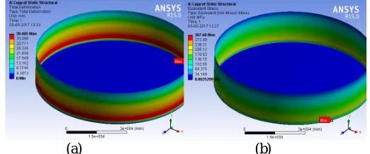
Fig 1: Static analysis result (a) Total deformation (b) Equivalent stress
minimum deformation is at the fixed supported face. Fig 1(b) shows the stress distribution on tank. Its maximum value is about 307 MPa. the stress is almost uniformly distributed over the body.
WIND LOAD ANALYSIS
(a) (b)
Fig 2: Wind load analysis result (a) Total deformation (b) Equivalent stress
The fig 2(a) shows the total deformation of the tank under wind load. The deformation is maximum at the top of front face of the tank. Front face is the face where the wind load is acting perpendicular direction. The minimum deformation is at the fixed supported face. And the maximum value is about 0.17 mm. Fig 2(b) shows the stress distribution on tank due to wind load. The maximum stress value is about 1.1MPa.
SLOSHING ANALYSIS
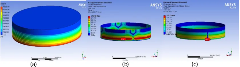
The fig 3(a) shows the pressure distribution during sloshing. The maximum pressure is at the bottom of tank. Then the result of sloshing is coupled with transient structural and analysed for deformation. Fig 3(b) shows the total deformation due to sloshing. Deformation is maximum at the bottom of tank, and is shown in red colour. Minimum value is shown in blue colour. The maximum deformation is about 24 mm. fig 3(c) shows the stress distribution its maximum value is shown in red. The blue strips in vertical direction is due to the stiffeners used in it. The analysis without stiffener has a higher deformation value. So that the stiffeners are added to the tank.
(a) (b) (c)
OBSERVATIONS
The table given below, shows the deformation and stress value during various analysis carried out in this work.
ANALYSIS TOTAL DEFORMATION
mm
VON-MISES STRESS MPa
STATIC ANALYSIS 39.485 307.68
WIND LOAD ANALYSIS 0.17 1.1916
SLOSHING ANALYSIS 24.048 157.79
V. CONCLUSION
STATIC ANALYSIS
The result shown in previous section, the maximum deformation occurred at the bottom region. This is due to the linear increase in hydrostatic pressure from top to bottom. Here the deformation has a bit higher value. To reduce the deformation some stiffeners can be added to the tank in various shapes and this can be taken as a future study. WIND LOAD ANALYSIS
For the wind load maximum deformation was occurred at the top shell course of storage tank. The thickness of upper shell course has the minimum thickness value, so that the deformation get the higher value at the top of tank.
SLOSHING ANALYSIS
For the sloshing analysis the maximum deformation was occurred at the bottom of the storage tank. This is due to the pressure is maximum at the bottom of the tank. The deformation calculated from the transient analysis was not exceeded the critical limit, so that the storage tank is safe under the analysed conditions.
REFERENCES
[1] R. Aziz Uras “Sloshing analysis of viscous liquid storage tanks”, Authored by a contractor of the U.S. Government under contract No: W-31-109-ENG-38.
[2] Saburo Shimada, Shigeru Noda, Takaharu Yoshida “Nonlinear sloshing analysis of liquid storage tanks subjected to relatively long-period motions”, Proceedings of ninth world conference on earthquake engineering. Vol VI, 1988.
[3] H. Akyildiz, Erdem Unal “Experimental investigation of pressure distribution on a rectangular tank due to the liquid sloshing”, Ocean Engineering. Vol 32:1503–1516, 2005.
[4]“American Petroleum Institute (API) 650”, 11th Edition
[5]“Code of practice for design loads (other than earth quake) for buildings and structures”, 1998.
[6]Syed Saif Uddin.“Seismic analysis of liquid storage tanks”, International Journal of Advanced Trends in Computer Science and Engineering, Vol.2, No.1, Pages : 357 – 362, 2016.
[7] Praveen K. Malhotra, Thomas Wenk, Martin Wieland “Simple procedure for seismic analysis of lquid-storage tanks”, Structural engineering international, Pages:197-201, 2000.
[8] Nicolae Zemthev “Seismic analysis of a vertical water tank”, SISOM and session of the commission of acoustics, Pages:458-470, 2011. [9] Praveen K. Malhotra, Parag Nimse “Seismic sloshing in a horizontal liquid storage tank”, Structural engineering international, Pages:466-473,
2014.
[10] Tatsuya Nakagawa “Then and now: The history of storage tank systems” Available: http://www.castagra.com/2013/05/then-and-now-the-history-of-storage-tank-systems/
[11] “Vancouver city council meeting minutes Attachment A: Written statements provided by item 5A/5B Public Hearing Testifiers”, 2014. [12] N. Hosseinzadeh “Seismic vulnerability analyses of steel storage tanks in an oil refinery complex using dynamic analyses”,The 14th world
conference on earthquake engineering, 2008.