Design of Broadband Microstrip Patch
Antenna for GPS Application
Balasubramanian.T(1), Jothichitra.R(2)
PG Scholar, Department of Electronics and Communication Engineering, Adhiparasakthi Engineering College,
Melmaruvathur, Tamilnadu, India (1)
Assistant Professor, Department of Electronics and Communication Engineering, Adhiparasakthi Engineering College,
Melmaruvathur, Tamilnadu, India (2)
ABSTRACT: In this work, a compact antenna is proposed for broadband navigation applications. The design of antennas mainly emphasizes miniaturization and compatibility. The widely used frequency for Geo-stationary satellite application that covers operating at an (12GHz–18GHz)bands has been developed with circular polarization operation. The simulated reflection loss less than -10dB and voltage standing wave ratio less than two. The certain results show that the proposed antenna implementation. Analysis and the design of microstrip antenna is achieves by adopting transmission line method. The simulation results of scattering parameter, VSWR, impedance matching, radiation pattern of the proposed antenna have been constructed. The Radiation pattern is achieved for various frequency conditions. Simulation results are presented, showing this compact antenna achieves the required satellite description in terms of frequency bandwidth, circular polarization bandwidth.
KEYWORDS: Broadband antenna, circularly polarized (CP), compact patch antenna, coupling feed, Global Navigation Satellite System (GNSS).
I.INTRODUCTION
II.ANTENNA STRUCTURE AND ANALYSIS
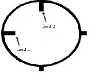
We intend to design a compact antenna with circular polarization that covers all the Global navigation frequencies. The antenna should be stable at all the interesting frequencies from the operating bands 12GHz–18GHz.Afourprobefeed three layer stacked patch configuration is adopted. A wideband feed network with equal phase difference of 90 and magnitude for the four feed points is located at the bottom layer shown in Fig 2.1. The proposed antenna is composed of Rogers RT/duroid 6006 substrate layer is used for reducing the size of the antenna. Substrate separated by air gap has massive amounts of power, the adoption of high permittivity substrate without an air gap between the patch and the ground plane improves the reliability of the antenna. The geometry of the proposed circularly polarized antenna consists of a square substrate of a coaxial line of the microstrip feed is optimized by achieving the input impedance matching.
Fig. 2.1.Microstrip Layout
It consists of four layers. The top layer is a square patch with two crossing rectangular slots and two circular holes for feeding that are located with an offset of from the center, where two feeding pads are placed. The second layer is aparasitic square patch for enhancing the bandwidth.It is isolated from the feed with a hole having radius 0.2mm and height 0.24mm. The third layeris the ground with the same size as the whole substrate 40 × 40.
Parameter Dimension(mm)
Ground length 40
Substrate thickness 1.6
Feeding pad radius 1.96
Feeding pad Height 0.24
Patch Length 16
Square Patch 14
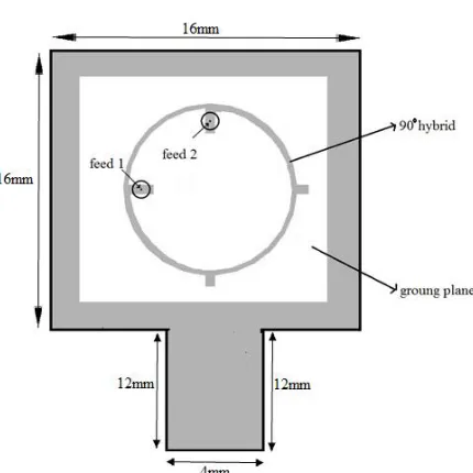
Fig. 2.2Geometry of the designed antenna
The designed microstrip structure and its simulated performance are shown in Fig. 2.2. A 900 hybrid and a grounded
ring are printed on the bottom layer. All the dimensions are listed in Table 2.1.
III.SIMULATION RESULTS
The configuration of the ring shaped antenna is designed on a substrate with Rogers 6006, relative permittivity 6.15 with a loss tangent of 0.0019. The proposed antenna consisting Rogers substrate, the design based on annular ring is etched on the patch of the microstrip feed line antenna. The thickness of the substrate is 1.6mm. It is non-conducting dielectric medium. All of them are substrate from the patch antenna elements. The patch elements made up of copper, it is a conducting material.
Fig. 3.1 S - Parameter versus Frequency Plot
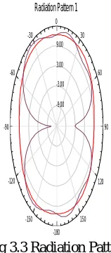
The return loss value is obtained by using S-parameter are measured in decibel. The simulatedreturn loss is shown in Fig 3.2. Return loss value is must be in the range of greater than the -10dB points are usually covered as the bandwidth of the antenna. The maximum value of return loss is -22.19dB achieved in 11.28GHz. The return loss characteristics of proposed antenna are -14.34dB for the resonant frequencies of 12.5GHz. The simulated radiation pattern of the proposed antenna is presented in Fig 3.3.The great agreement of the simulation validates the design.
Fig 3.2 Voltage Standing Wave Ratio
6.00 8.00 10.00 12.00 14.00 16.00 18.00
Freq [GHz] -22.50 -20.00 -17.50 -15.00 -12.50 -10.00 -7.50 -5.00 -2.50 d B (S (1 ,1 )) HFSSDesign1
XY Plot 1 ANSOFT
m1 m2 m3 m4 m5 m6 Curve Info dB(S(1,1)) Setup1 : Sweep Name X Y
m1 9.6600 -10.3102 m2 10.3200 -14.3062 m3 10.9800 -20.5715 m4 12.3000 -14.0404 m5 12.9600 -10.6208 m6 11.2800 -22.1955
6.00 8.00 10.00 12.00 14.00 16.00 18.00
Freq [GHz] 1.00 1.50 2.00 2.50 3.00 3.50 4.00 a b s (V S W R (1 )) HFSSDesign1
XY Plot 2 ANSOFT
m1 m2 m3 m4 Curve Info abs(VSWR(1)) Setup1 : Sweep Name X Y
m1 9.6000 1.9201 m2 10.2000 1.5417
Fig 3.3 Radiation Pattern
IV.CONCLUSION
A Compact and Robust circularly polarized microstrip patch antenna was designed and simulated using High Frequency Simulation Structure tool [8]. The simulated results of antenna consists return loss, VSWR and radiation patterns achieved their optimum values. The Return loss valueachieved for less than-10dB and the voltage standing wave ratio less than two. A circularly polarized patch antenna with different shapes of parasitic shorting strips for a new size reduction technique has been investigated analytically. The radiation pattern can be obtained for different shapes of shorting strip. Size reduction of ring shaped patch antenna can be achieved most efficiently by using high permittivity substrate.Simulation results good enough to satisfy our requirement to fabricate it on hardware. The proposed antenna is suitable for GPS satellite communications applications.
V.FUTURE WORK
Fabrication of prototype antenna will be carried out in future and measured results will be compared with simulated results.The size of the antenna will be reduced. The reduced size of the antenna will cover the all the parameters of navigationapplications.In order to examine the quality and range, radiation with high gain are required for some application.Simulation of proposed antenna for various substrate thicknesses to obtain required gain and bandwidth coverage’s.
ACKNOWLEDGEMENT
We authors would like to thank our Correspondent, Management and Lab Technician for their kind support to complete our research work successfully.
REFERENCES
-9.00 -3.00 3.00 9.00
90 60 30 0
-30
-60
-90
-120
-150
-180 150
120
HFSSDesign1
Radiation Pattern 1 ANSOFT
Curve Info dB(rETotal) Setup1 : LastAdaptive Freq='12.5GHz' Phi='0deg'
low angle multipath,” IEEE Trans. Antennas Propag., vol. 55, no. 8,pp. 2358–2366.
[6] Y.Gou, S.Yang, Q. Zhu, and Z.Nie, 2013, “A compact dual-polarized double E-shaped patch antenna with high isolation,” IEEE Trans. Antennas Propag., vol. 61, no. 8, pp. 4349–4353.
[7] M. Heckler, R. Farias, L. Pereira, E. Schlosser, and C. Lucatel, 2013, “Design of circularly polarized annular slot antennas for satellite navigation systems,”in Proc. 7th EuCAP, pp. 361–365.
[8] Ansoft HFSS. Ver. 12, Ansys Corporation, Framingham M.A [Online]. Available: www.ansoft.com.
[9] S.-L. Yang and K.-M.Luk, 2008, “A wideband l-probes fed circularly-polarizedreconfigurable microstrip patch antenna,” IEEE Trans. AntennasPropag., vol. 56, no. 2, pp. 581–584.
[10] Y. Li, Z. Zhang, Z. Li, J. Zheng, and Z. Feng, 2011, “High-permittivitysubstrate multiresonant antenna inside metallic cover of laptop computer,” IEEE Antennas Wireless Propag. Lett., vol. 10, pp. 1092–1095.
[11] C. A. Balanis, 2005, Antenna Theory Analysis and Design, 3rd ed.Hoboken, NJ, USA: Wiley. [12] D. M. Pozar, 1998, Microwave Engineering, 2nd ed. New York, NY, USA:Wiley.
[13] W.-T. Hsieh, T.-H.Chang, and J.-F. Kiang, 2012, “Dual-band circularly polarizedcavity-backed annular slot antenna for GPS receiver,”
IEEETrans. Antennas Propag., vol. 60, no. 4, pp. 2076–2080.
[14] K.-F. Tong and J.-J. Huang, 2008, “New proximity coupled feeding methodfor reconfigurable circularly polarized microstrip ring antennas,”
IEEETrans. Antennas Prop., vol. 56, no. 7, pp. 1860–1866.
[15] X.-Y. Sun, Z.-J.Zhang, and Z.-H. Feng, 2011, “Dual-band circularly polarizedstacked annular-ring patch antenna for GPS application,”
![Fig. 3.1 S - Parameter versus Frequency Plot Freq [GHz]](https://thumb-us.123doks.com/thumbv2/123dok_us/1644416.1205622/4.595.186.409.177.382/fig-s-parameter-versus-frequency-plot-freq-ghz.webp)