Laser-driven shock experiments to investigate mitigation ability of polymeric
foams
PierrePradel1,∗,FrédéricMalaise1, andThibautde Rességuier2
1CEA CESTA, 15 avenue des Sablières CS60001, 33116 Le Barp Cedex, France
2Institut P’ UPR3346 CNRS-Université de Poitiers-ENSMA, 11 boulevard Marie et Pierre Curie, 86962 Futuroscope Chasseneuil
Cedex, France
Abstract.Polymeric foams are widely used in many industrial fields as thermal insulators, structural materials or shock wave mitigators. Polymeric foams would be valuable candidates to protect structures against intense mechanical stress wave loadings generated by laser irradiation or high velocity impact of very small debris. This article presents the results of laser-driven shock experiments performed on polymeric foams to investigate their mitigation ability. The targets consisted of thin aluminum front plate (250µm-thickness), 1 mm and 2 mm-thick samples made of expanded polyurethane foam (320 kg/m3) or syntactic epoxy foam (624 kg/m3), and 12µm-thick aluminum foil. The laser beam provided 20 J in 25 ns and was shot through water confinement of the front plate. The dynamic responses of the foams were investigated by measuring time-velocity profiles at the rear surface. Preliminary tests were performed on thin aluminum plate in order to calibrate the stress wave loadings. A dynamic explicit one-dimensional hydrocode was used to simulate the experiments and validate the calibration of pressure generated under laser irradiation. Then, the numerical simulations were used to analyze the velocity profiles recorded at the rear surface of both foams. The dynamic macroscopic response of the foams was described by a phenomenological compaction model. The model has been validated by numerical correlations with the experimental results. The input pressure (front aluminum plate) and the output one (fictitious PMMA plate placed behind foam samples) were compared by help of numerical simulations. The ratio between input and output pressures could achieve 75. Polyurethane foam better mitigated shock waves below 2 GPa, and epoxy foam was better above 2 GPa.
1 Introduction
Polymeric foams are commonly used in aerospace, auto-motive [1, 2], marine [3] and military industries [4] for the protection against crashes or high velocity impacts. Their light weight and their energy absorption abilities are of great interest to develop efficient systems that mitigate the effects of intense (several GPa) and brief (1-1000 ns) stress wave loadings. At CEA CESTA, these loadings are representative of the ones that will be carried out with the Laser MégaJoule (LMJ). Effective protection systems against laser irradiation or very high velocity impacts of small debris must be developed to protect some diagnos-tics or samples support devices.
The expected devices consist of a metal shield, to in-teract with the laser beam or debris, and a mitigator layer, to reduce the intensity of the stress waves transmitted to the component to protect. A rigid closed cell polyurethane foam (320 kg/m3) and a syntactic epoxy foam (624 kg/m3)
have been chosen for their energy absorption abilities. Previous works permit to identify the deformation mechanisms of these foams under quasi-static loadings [3, 5, 6] or Split Hopkinson Pressure Bar experiments [3, 7]. Several gas gun experiments have been performed to deter-mine shock Hugoniot [8, 9]. Although these experiments
∗e-mail: [email protected]
are accurate to study the behaviour of the foams at high strain rates, the load durations are not completely repre-sentative of laser irradiation or high velocity impacts.
The objective of this paper is to investigate the dy-namic behaviour and the mitigation ability of both poly-meric foams by performing laser-driven shock experi-ments. Numerical simulations have been carried out by us-ing a phenomenological compaction model. Accordance between experimental and numerical data is presented. In-put and outIn-put pressures have then been calculated and compared to investigate the mitigation ability of the two foams.
2 Experimental
2.1 Materials
66%. According to literature data [10], the density of fully dense polyurethane is 1240±40 kg/m3.
Fig. 1. Microstructure of polyurethane foam obtained by X-ray tomography.
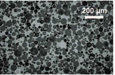
The second foam is a syntactic epoxy foam obtained by adding glass microspheres during the polymerization reaction of an epoxy resin. The diameter of the micro-spheres is about 60 µm, and the thickness of the walls
of the spheres is around 1µm (see optical microscopy in
Fig. 2). The density of the foam is about 624±10 kg/m3
and the porosity is around 62%. The density of fully dense epoxy is between 1190 and 1490 kg/m3.
Fig. 2. Microstructure of epoxy foam obtained by optical mi-croscopy.
2.2 Experimental set-up
The experimental set-up used for these laser-driven shock experiments is shown in Fig. 3. The targets consist of a 250 µm-thick aluminum front plate bonded to 1 mm or
2 mm-thick foam samples. To delay the expansion of the plasma, water confined regime configuration was used by depositing a few drops of water on the front side of the aluminum plates. It permits to increase the ablation pres-sure and to double the pulse duration [11]. The thickness of this water confinement is about 1 mm.
The dynamic responses of the foams have been in-vestigated by measuring the velocity histories at the rear surface by using a VISAR (Velocity Interferometer Sys-tem for Any Reflector). A 12µm-thick aluminum foil is
bonded to the rear surface of the samples to provide bet-ter reflection of the laser beam used by the inbet-terferome- interferome-ter. The thickness of the aluminum foil is small enough in
Fig. 3.Laser-driven shock experimental set-up.
front of the thickness of the foams to consider that the rear surface of the foam samples is a free surface.
Experiments have been performed with the laser of In-stitut P’. It delivers pulses of 20 J for a duration of 25 ns with a spot diameter of about 5-6 mm, which corresponds to intensities of about 3-4 GW/cm2. During the
experi-mental campaign, the laser energy has been set between 9 and 20 J (Tab. 1). Taking into account the confinement, the pulse duration reaches 50 ns and the pressures are ranging from 0.9 to 2.6 GPa.
Table 1.Parameters of laser-driven shock experiments.
Foam Shot number Thickness Energy (mm) E(J)
Polyurethane
pu1000_07 0.971 16.92 pu1000_09 0.993 17.11 pu1000_10 0.950 13.16 pu1000_23 0.988 18.05 pu2000_15 2.018 18.80 pu2000_16 2.017 12.78 pu2000_22 2.016 17.11
Epoxy
epo1000_11 0.994 19.18 epo1000_14 1.013 12.97 epo2000_18 1.990 18.24 epo2000_21 2.005 18.99
3 Results and discussion
3.1 Calibration of the stress wave loadings
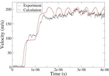
The presence of a confinement prevents the analytical calculation of the ablation pressure using the Grün for-mula [12]. Thus dedicated laser shots have been per-formed on 250µm-thick aluminum samples in order to
cal-ibrate the stress wave loadings by using an inverse method. The ablation pressure, the pulse duration and the shape of the release are determined to reproduce the experimental velocity profiles, shown in Fig. 4, for two laser energies.
Fig. 4.Velocity profiles of aluminum free surface.
in Fig. 5. The correlations between numerical and exper-imental velocity profiles are fairly good (Fig. 4). It vali-dates the ablation pressure profiles for laser energies be-tween 13 and 17 J.
Fig. 5.Ablation pressure profiles.
3.2 Experimental results
Velocity profiles measured at the rear surface of 1 mm-thick foam samples are shown in Fig. 6 and 7 for the shots #pu1000_09 and #epo1000_11. During the propagation through the foam, the stress wave splits in an elastic pre-cursor and a compaction wave. The first velocity level is associated to the arrival of the elastic precursor. The level of this precursor is about 80 m/s for polyurethane foam, and 90-100 m/s for epoxy foam. At the rear surface of the foam, the elastic wave is reflected into release waves which interact with the compaction wave. The compaction wave is not registered during these experiments.
3.3 Numerical results
The dynamic behaviour of polyurethane and epoxy foams is represented by the SRI phenomenological compaction model [15]. The parameters of the models have been vali-dated by comparisons between numerical and experimen-tal results. The results of quasi-static, magnetic pressure
Fig. 6.Comparison between experimental and numerical veloc-ity histories at the rear surface of polyurethane foam.
Fig. 7.Comparison between experimental and numerical veloc-ity histories at the rear surface of epoxy foam.
and plate impact experiments have been used for this cali-bration. During these previous studies, the dynamic com-paction threshold has been determined: it was 21 MPa for polyurethane foam, and 72 MPa for epoxy foam.
The laser-driven shock experiments have been simu-lated by using the one-dimensional hydrocode. The tar-gets have been discretized to correctly capture the laser shock (mesh size between 1 and 40 µm). The
computa-tions have been initiated by applying the ablation pres-sure profiles deduced from calibration experiments. The comparisons between experimental and numerical data are shown in Fig. 6 and 7. The arrival times of the waves and the velocity levels are fairly reproduced, which validates the compaction models under laser-driven shock loadings.
3.4 Energy absorption
To highlight the energy absorption abilities of the foams, we have simulated the propagation of a laser shock wave through a target made of 250 µm-thick aluminum plate,
incident stress wave and the foam properties (polyurethane or epoxy foam).
Fig. 8.Evolution of transmitted stress into the window as a func-tion of incident stress into aluminum.
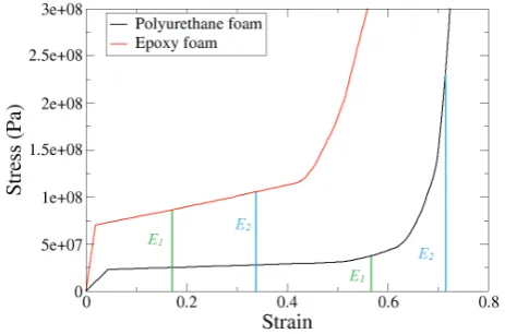
Fig. 9.Comparison of the stress-strain curves of the foams.
If the incident stresses are below 2 GPa, the transmit-ted stresses calculatransmit-ted into the PMMA window are lower with polyurethane foam. For these loadings, polyurethane foam is a better shock wave mitigator than epoxy foam. Beyond 2 GPa, it is the opposite. We notice that the mit-igation is very efficient since the intensity of the stresses can be divided by a factor up to 30 using polyurethane foam, and a factor up to 25 using epoxy foam. The en-ergy per unit volume absorbed by the foam is represented by the area under the stress-strain curve [16]. As shown in Fig. 9, since the compaction plateau of polyurethane foam is below the epoxy foam one, the transmitted peak stress is lower. This is the case when the absorbed en-ergy is equal toE1(see Fig. 9). When fully densified state is achieved into polyurethane foam, epoxy foam becomes more efficient. This is the case when the absorbed energy is equal toE2. The transmitted stress obviously depends on the foam thickness: it decreases when the foam thick-ness increases, and the ratio between the transmitted and the incident stresses can reach 75 if the foams thickness is 2 mm.
4 Conclusion
Laser-driven shock experiments have been performed to investigate the mitigation abilities of two polymeric foams. After a calibration step on aluminum targets, the velocity profiles measured at the rear surface of both foams have been simulated. The good agreement between experimen-tal and numerical results validated the use of the models under laser stress wave loadings. Thus, these models have been used to analyze the energy absorption abilities of the foams. Polyurethane foam is a better mitigator than epoxy foam for stress levels below 2 GPa. Above 2 GPa, it is the opposite.
References
1. F.A.O. Fernandes, R.T. Jardin, A.B. Pereira, and R.J. Alves de Sousa. Comparing the mechanical performance of synthetic and natural cellular materials. Materials & Design,82335-341 (2015)
2. L. Di Landro, G. Sala, and D. Olivieri. Deformation mechanisms and energy absorption of polystyrene foams for protective helmets, Polymer Testing, 21 217-228 (2002)
3. A. Pellegrino, V.L. Tagarielli, R. Gerlach, and N. Petrinic. The mechanical response of a syntactic polyurethane foam at low and high rates of strain, In-ternational Journal of Impact Engineering, 75214-221 (2015)
4. J.C. Gowda. A flexible syntactic foam for shock mitiga-tion, PhD thesis, North Carolina A&T State University (2011)
5. H. Jmal. Identification du comportement quasi-statique et dynamique de la mousse de polyuréthane au travers de modèles à mémoire, PhD thesis, Université de Haute Alsace (2012)
6. Z.H. Tu, V.P.W. Shim, and C.T. Lim. Plastic deforma-tion modes in rigid polyurethane foam under static load-ing, International Journal of Solids and Structures, 38
9267-9279 (2001)
7. W. Chen, F. Lu, and N. Winfree. High-strain-rate com-pressive behavior of a rigid polyurethane foam with vari-ous densities, Experimental Mechanics,4265-73 (2002) 8. E. Zaretsky, Z. Asaf, E. Ran, and F. Aizik. Impact re-sponse of high density flexible polyurethane foam, Inter-national Journal of Impact Engineering,391-7 (2012) 9. D.M. Dattelbaum, J.D. Coe, C.B. Kiyanda, R.L.
Gus-tavsen, and B.M. Patterson. Reactive, anomalous com-pression in shocked polyurethane foams, Journal of Ap-plied Physics,115174908 (2014)
10. S.P. Marsh. LASL shock Hugoniot data, University of California Press (1980)
11. L. Berthe. Processus de claquage de milieux transpar-ents sous irradiation laser. Application au choc laser en régime de confinement par eau, PhD thesis, Université de Paris Sud (1998)
13. A.V. Bushman, I.V. Lomonosov, and V.E. Fortov. Equations of state for metals at high energy density, In-stitute of Chemical Physics (1992)
14. D.J. Steinberg, S.G. Cochran, and M.W. Guinan. A constitutive model for metals applicable at high-strain-rate, Journal of Applied Physics51(1980)
15. L. Seaman, R.E. Tokheim, and D.R. Curran. Com-putational representation of constitutive relations for porous materials, Technical report, Stanford Research Institute (1974)