www.ijiset.com
201
Experimental Study on Light Transmitting Concrete
Awadhesh Kumar¹, Rahul Ahlawat²
¹Associate Professor, ²M.Tech (Structure Engineering) student,
Department of Civil Engineering, Delhi Technological University, Delhi, India.
ABSTRACT:
The recent economic and infrastructure developments made us to depend on artificial sources of energy. Thus, Light transmitting concrete is the need of hour. Light transmitting concrete allows natural (i.e. sunlight) or any other light to pass through it. Thus reduces electricity consumption in the buildings and makes easy for them to achieving higher LEED (Leadership in Energy and Environmental Design) rating. It has all those properties which an eco-friendly technique should have to keep up the green building concept into consideration, as it increases the use of natural resource i.e. sunlight, which is natural light and it reduces the use of electricity, thus, saving power consumption. Light transmitting concrete also gives aesthetically beautiful surface. It is made up of cement, sand, coarse aggregates and thousands of plastic optical fiber strands placed in alternate layers. But, no construction material can be used until it satisfies all constructional requirements. For this purpose, experimental study on light transmitting concrete has been carried out to determine it’s light transmittance characteristics with the help of Photometer device which is used to find the intensity of light in terms of lumens. The Compressive strength of light transmitting concrete is also found out by testing its cubes with the help of compression testing machine. The test results show that light transmittance ratio up to 5.5% can be achieved by using 4% plastic optical fibers in light transmitting concrete. Experimentally found compressive strength results show that there is very little or almost no loss of strength in light transmitting concrete as compared to the traditional concrete. Light transmitting concrete has a very bright future in civil engineering constructions owing to its unique characteristics
of transmitting light. It is a tremendous innovation in terms of aesthetics and architectural aspects also it gives very pleasing appearance and can be used very effectively for decorative purposes. Additionally, it encourages the green building concept by reducing the dependence on artificial light sources during the day time.
Keywords: Photometer, light intensity
transmittance, lumens, plastic optic fibers and compressive strength.
INTRODUCTION
Concrete is a very important construction material, composed of cement (commonly Portland cement) as well as other cementitious materials such as fly ash and slag, aggregate, water, and chemical admixtures. Concrete ingredients solidify and harden after mixing with water due to chemical process known as hydration. The water reacts with the cement, which bonds the other components together, eventually creating a stone-like material. Pavements, architectural structures and motor ways, bridges, parking structures, walls, footings, fences and poles are made of concrete. Concrete is used more than any other man-made material in the world.
202
up to twenty meters. It is popularly used in green buildings to save electricity.
Need of Light Transmitting Concrete
This concrete is very important for sustainable development and green building point of view, as it allows, use of natural light more efficiently without compromising much on strength parameter. For green buildings, according to IGBC (Indian Green Building Council), 50% of day light is mandatory which accounts for 3 credits in a green building. Light transmitting concrete may allows sufficient light inside the building, thereby making it easier to achieve higher rating for buildings.
Due to increase in land cost, requirement of increased usable space, engineers are being compelled to go for high rise buildings and skyscrapers. In these structures, people’s optical activity requirements are met with the help of artificial sources of energy only. Complete dependence on artificial sources has adverse impact on our environment and health of people. As the production of artificial sources of energy, pollutes our environment by releasing harmful by products into the environment.
Light transmitting concrete or translucent concrete is a special type of concrete that allows light to pass through it. It is made up of cement, sand, coarse aggregate and optical fibers, placed in alternate layers. Light transmitting concrete allows natural sunlight or any visible light to pass through it, thus, increasing the light content in the building to enhance people’s optical activity. Passing of light through optical fiber is based on the principle of total internal reflection of light in the core of the plastic optical fiber. When light falls on one end of the optical fiber, it gets totally internally reflected in the fiber and gets transmitted to the other end of fiber.
Very limited research has been done on various properties of light transmitting concrete regarding its suitability as construction material. The main objective of this experimental program is to study its light transmitting and strength characteristics by varying plastic optical fiber percentage and concrete grade which may produce different effects on performance.
Functional Principle of Light Transmitting Concrete
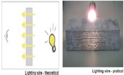
Diffused natural light and sun light provide full spectrum of colors shining through the concrete panels. Sunlight is the most in- expensive light source. If the panel is mounted free standing or in front of a window, one will not need any artificial light source on other side of light source. Transparent concrete or translucent concrete works based on “Nano-Optics”. Fig. 1 shows optical fibers pass as much light when tiny slits are placed directly on top of each other. Optical fibers in the concrete act like the slits and carry the light across the concrete.
Fig. 1 functional principle of light transmitting concrete
Total internal reflection
When light traveling in an optically dense medium hits a boundary at a steep angle (larger than the1T1Tcritical angle1T1Tfor the boundary), the light
is completely reflected. This is called total internal reflection. This effect is used in optical fibers to confine light in the core. Fig.2 demonstrates that light travels through the fiber core, bouncing back and forth off the boundary between the core and cladding. Because the light must strike the boundary with an angle greater than the critical angle, only light that enters the fiber within a certain range of angles can travel down the fiber without leaking out. This range of angles is called the1T1Tacceptance cone1T1Tof the fiber.
The size of this acceptance cone is a function of the refractive index difference between the fiber's core and cladding.
www.ijiset.com
203
core of fiber. The1T1Tsine1T1Tof this maximum angle is
the1T1Tnumerical aperture1T1T(NA) of the fiber. A fiber
with a larger NA requires less precision to splice and work with, than fiber with a smaller NA. Single-mode fiber has a small NA. Fig.2 shows propagation of light in a multi mode optical fiber.
LITERATURE REVIEW
Kashiyani et. al. [1] studied light transmitting concrete using 4% to 5% optical fibers. The fibers of diameter from 2 μ m to 2 mm were used in alternate layers with concrete. The concrete was based on the principle of total internal reflection of optical fibers.
Bhusan et. al. [2] constructed translucent concrete block and discussed their use in walls, ceiling to make it architecturally pleasing, illuminating speed bumps, use of sidewalks, various interior and exterior surfaces of the buildings to make them aesthetically beautiful. Plastic optical fibers (POFs) have various advantages like no radiation, not affected by radio magnetic interference, radio frequency and noise. POFs are by far the best replacement for glass due to strength and giving more privacy.
Fig.2 propagation of light in a multi mode optical fiber
Juan and Zhi [3] discussed the development of smart transparent concrete based on its excellent properties of smart sensing. By dealing its usage and advantages, it makes smart construction, reduces power consumption for illumination and use of optic fibers to sense stress in structures. They concluded that transparent concrete does not lose strength parameter when compared to conventional concrete. It can be used for the best architectural appearance of the building and can be used
where light cannot reach with appropriate intensity.
Kamdi, B.A. [4] found that light transmitting concrete can be used almost anywhere, where glass of traditional concrete can be used. This concrete has dual effect, one on strength and other to transmit light. It also retains privacy and can be used for structural support. Its disadvantage is that it is expensive.
Neha and Bhole [5] prepared translucent concrete using optical fibers. For preparing mould, first polymer craft clay was spread into a flat circle, a ring of spray paint was used to fix over clay for using it as a mould then optical fibers were placed individually in the mould and finally concrete was poured slowly. After 24 hours, polymer clay was pulled and then plastic ring was removed. The concrete was allowed to dry and extra fibers were cut. Sand paper was used to polish. The prepared concrete was able to pass light through it.
Zhi et. al. [6] studied the light transmitting characteristics of light transmitting concrete by making four cube specimens of 100mm size with cement: sand: water in proportion of 1: 2: 0.44 and plastic optic fibers of 3.14%, 3.80%, 4.52% and 5.3%. They observed that light transmittance was varying from 1% to 2.25% of the incident light.
Momin et. al. [7] used six specimens of translucent concrete with varying POF as 1%, 2%, 3%, 4%, 5% and 6% with diameter of POF as 1mm. It was observed that for halogen lamp, transmittance varied as 0.29%, 0.59%, 0.98%, 1.41%, 1.83% and 2.36%, while for incandescent lamp of 200W, the transmittance was observed as 0.41%, 0.82%, 1.22%, 1.72%, 2.15% and 2.59% respectively. The difference in transmittance is due to light scattering angles of chosen lamps were different.
204
They concluded that a tilt of 30P
0
P
for the panel transmitted the maximum amount of light among all the tilt angles considered and it is natural because fibers absorb radiation of sunlight.
Shanmugavadivul et. al. [9] used M20 concrete for 150mm size cubes to determine compressive strength of conventional concrete and light transmitting concrete at 7days, 14days and 28 days. They found that strength is comparable.
Jimenaz and Fernandez [10] used glass fibers of 0%, 5%, 10% and 30% and determined compressive strength of concrete at 7days and 28 days, which was reduced gradually from 33.6 MPa to 25.7 MPa at 7 days and 34.2 MPa to 26.9 MPa at 28 days.
Bashbash et. al. [11] used 50 mm cubes with POF of 4% having diameters of fibers as 1.5cm, 2.0cm, 2.5cm and 3.0cm. They observed that for the same percentage of fibers, the larger diameter concrete has higher strength.
Paul and Dutta [12] used chloride diffusion coefficient method (or electric flux method) to test permeability of translucent concrete, which can rapidly evaluate permeability of concrete by measuring electric energy through concrete. Concrete cylinders of 100mm diameter and 50mm height with 0%, 3% and 6% POF were chosen for the test and electric energy was recorded by electric flux detector. In order to evaluate the effect of interface bonding on the impermeability property, each model of the specimen was divided in two types i.e. one was covered with epoxy resin at the border of POF and other was un-covered. It was observed that total electric current without covering with epoxy resin were 1897.8 C, 3152.6 C and 3602.2 C for 0%, 3% and 6% respectively while total electric current traversing the specimens covered by resin were reduced to 2147 C and 3357 C for 3% and 6% POFs respectively.
EXPERIMENTAL PROGRAM
Materials
The properties of materials used in light transmitting concrete are determined in laboratory as per relevant code of practice.
Different materials used in this experimental study were cement, sand, coarse aggregates (passing 10mm IS sieve), plastic optical fiber and water. Results of the tests conducted, to determine physical properties of materials are reported and discussed in this section. The materials in general conformed to the specifications laid down in the relevant Indian Standard Codes.
Cement
Ordinary Portland cement of 43 grade conforming to IS: 269 - 2015 [13] was used. Cement was tested in accordance with IS: 4031 (Part 1, 4, 5 and 11) [14 - 17].
Fine aggregate
River sand has been sieved from IS 1.18mm sieve and used. The fineness modulus of the sand was 2.404. The bulk density of sand in compacted and loose state was also determined and was found as 1982 kg/mP
3
P
and 1668 kg/mP
3
P
respectively. The specific gravity of the sand was determined in accordance with IS: 2386 (Part 3) – 1963 [18] and found as 2.63.
Coarse aggregate
Coarse aggregate of 10 mm and down was used. The fineness modulus of coarse aggregate was 5.94. The bulk density of coarse aggregate in compacted and loose state was also determined and was found as 1649.7 kg/mP
3
P
and 1452.9 kg/mP
3
P
respectively. The specific gravity of coarse aggregate was determined in accordance with IS: 2386 (Part 3) – 1963 [18] and found as 2.50.
Plastic optical fiber (POF)
An1T1Toptical fiber is a flexible, transparent fiber
made of extruded glass (silica) or plastic, slightly thicker than a1T1Thuman hair. It can function as
a1T1Twaveguide, or “light pipe”,1T1Tto transmit light
between the two ends of the fiber.1T1TThe field
of1T1Tapplied science1T1Tand1T1Tengineering1T1Tconcerned
with the design and application of optical fibers is known as1T1Tfiber optics.
Optical fibers (Fig. 3) are widely used in1T1Tfiber-optic communications, where they
permit information transmission over longer distances and at higher1T1Tbandwidths1T1T(data rates)
www.ijiset.com
205
with less1T1Tloss1T1Tand are also immune
to1T1Telectromagnetic interference. Fibers are also
used for1T1Tillumination, and are wrapped in
bundles so that they may be used to carry images, thus allowing view in confined spaces. Specially designed fibers are used for a variety of other applications, including1T1Tsensors1T1Tand1T1Tfiber
lasers.
Optical fibers typically include a1T1Ttransparent1T1Tcore1T1Tsurrounded by a
transparent1T1Tcladding1T1Tmaterial with a lower1T1Tindex
of refraction. Light is kept in the core by1T1Ttotal
internal reflection. This causes the fiber to act as a1T1Twaveguide. Fibers that support many
propagation paths or1T1Ttransverse modes1T1Tare
called1T1Tmulti-mode fibers1T1T(MMF), while those
only support a single mode are called1T1T
single-mode fibers1T1T(SMF). Multi-mode fibers generally
have a wider core diameter, and are used for short-distance communication links and for applications where high power must be transmitted. Single-mode fibers are used for most communication links longer than 1,000 meters.
Optical fibers have a wide number of applications. They are used as1T1Tlight guides1T1Tin
medical and other applications where bright light needs to be shown on a target without a clear line-of-sight path. In some buildings, optical fibers route sunlight from the roof to other parts of the building.1T1TOptical fiber lamps1T1Tare used for
illumination in decorative applications, including1T1Tsigns,1T1Tart, toys and artificial1T1TChristmas
trees.1T1TSwarovski1T1Tboutiques use optical fibers to
illuminate their crystal showcases from many different angles while only employing one light source. Optical fiber is an intrinsic part of the light transmitting concrete.
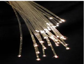
Fig. 3 bundle of optical fibers
An optical fiber is a cylindrical1T1Tdielectric
waveguide1T1T(non-conducting1T1Twaveguide) that
transmits light along its axis, by the process of1T1Ttotal internal reflection. The fiber consists of
a1T1Tcore1T1Tsurrounded by a1T1Tcladding1T1Tlayer, both of
which are made of dielectric1T1Tmaterials. To
confine the optical signal in the core, the1T1Trefractive index1T1Tof the core must be greater
than that of the cladding. The boundary between the core and cladding may either be abrupt, in1T1Tstep-index fiber, or gradual, in1T1Tgraded-index
fiber.
These can have diameters up to 2mm. POF allows to transmit sunlight or light from any source to pass through it. When used in concrete, these fibers transmit light that falls on one face of the concrete to the other face. There is little or no signal loss in the POF when light passes through its core. POF of diameter 0.5mm has been used in preparing samples of the present study. Fig. 3 shows transmitting of light through plastic optical fibers.
Water
Clean potable tap water available in the laboratory was used in making concrete specimens and their curing.
Preparation of Light Transmitting Concrete Specimens
Preparation of moulds and installation of POF in the moulds
206 Preparation of light transmitting concrete
specimens
Concrete of two nominal mix proportions i.e. 1: 1.5: 3 (cement: sand: coarse aggregate) with water cement ratio of 0.45 and 1: 1: 2 with w/c ratio of 0.45 were used for preparing cubes of 100 mm size. Varying percentage of POFs as 0.25%, 0.50%, 0.75%, 1.00%, 1.25%, 1.50%, 1.75%, 2.00%, 2.25%, 2.50%, 2.75%, 3.00%, 3.25%, 3.50%, 3.75%, 4.0% were used to study strength variation and light transmittance characteristics of POF (plastic optical fibers), because more than 4% POFs volume will reduce the strength of concrete significantly and the concrete may not be of any use. Also, manually installation of POFs might be difficult and concrete may be honeycombed.
After placing fibers, plates were fitted to the wooden moulds and concrete was poured in the moulds, after placing mould on the vibrating table. By giving vibrations, concrete was
Fig. 4 moulds with fibers in place
Fig. 5 perforated wooden plates
Table 1 Number of plastic optical fiber strands as per percentage of fibers used
percentage of plastic optical fibers
number of plastic optical fiber strands
used
0.25 125
0.50 250
0.75 375
1.00 500
1.25 625
1.50 750
1.75 875
2.00 1000
2.25 1125
2.50 1250
2.75 1375
3.00 1500
3.25 1625
3.50 1750
3.75 1875
4.00 2000
completely filled in the moulds with no void left between the fibers and concrete. After casting, the cubes moulds were placed under wet jute bags for 24 hours, thereafter cubes were removed from moulds and were then immersed in water for 7 days (minimum curing period as recommended by IS: 456-2000 [19]). Fig. 6 shows cubes taken out, after curing them for 7 days in water.
Table 1 shows number of 0.5 mm diameter POF (plastic optical fiber) strands as per various percentage of plastic optical fiber used in the cubes.
The diameter of 1 POF = 0.5 mm Area of 1 POF = 0.197 mm² Size of cube = 100mm Cross section area of a cube = 10000 mm² 1% POF = 10000 x 1/100 = 100 mm² Area of POF required for 1% = 100 mm² Number of POF required for 1%
= (1 x 100 mm²)/0.197 = 500 approx.
www.ijiset.com
207
Study of Experimental Properties
Test for light transmittance property
Light transmittance test was performed to study the light transmittance characteristics of the specimens. It is most important test to be performed, as main purpose of translucent concrete is to transmit light. Transmittance ratio is found by measuring intensity of incident light and transmitted light. Intensity of light is measured with the help of Photometer, which measures intensity of light in terms of lumens.
Experimental setup for light guiding property test
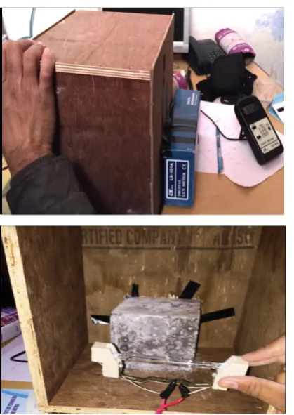
To study light guiding property of light transmitting concrete, samples of POF volume ratios of 0.25%, 0.50%, 0.75%, 1.00%, 1.25%, 1.50%, 1.75%, 2.00%, 2.25%, 2.50%, 2.75%, 3.00%, 3.25%, 3.50%, 3.75%, and 4.00% were cast. The transmittance was measured by Photometer (or lux meter) that measures intensity of light in lumens, having range of 0.1 to 1,00,000 lux. The incandescent lamp with 100W (1,500 lumens), 200W (3,000 lumens) and halogen lamp with 500W (11,000 lumens) were chosen as light source, because the range of photometer is divided in three classes i.e. class A, class B, class C as given in Table 2 and Table 3 indicates that these three light sources i.e. two incandescent lamp of 100W (1,500 lumens) and 200W (3,000 lumens), and a halogen lamp of 500W (11,000 lumens) satisfies light intensity of three classes. So, we simply used incandescent light source of 100W and 200W and a halogen lamp of 500W to determine transmittance percentage of light, which may be of any light intensity. A wooden box was fitted with light source (Fig. 7) on one face and a Photometer attached on other face in the box, such that all light transmitted from the sample falls in the box of Photometer. Readings of transmitted light were noted from Photometer. Precautions were taken to see that the box of photometer was correctly installed and full transmitted light was falling in the box.
Table 2 Range of photometer for measuring light intensity divided in three classes
range of Photometer light intensity in lumens
Class A 1 to 2,000 lumens
Class B 2,000 to 10,000 lumens
Class C 10,000 to 20,000 lumens
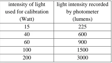
Calibration of the Photometer was done using incandescent light sources of various intensities e.g. 15 Watt, 40 Watt, 60 Watt, 100 Watt, 200 Watt and is given in Table 3.
Compressive strength test on light transmitting concrete
Cubes of 100mm size with various volumes of plastic optical fibers i.e. 0.25%, 0.50%, 0.75%, 1.00%, 1.25%, 1.50%, 1.75%, 2.00%, 2.25%, 2.50%, 2.75%, 3.00%, 3.25%, 3.50%, 3.75, 4.00% were load tested. Average compressive strength of three specimens for each POF percentage and each mix proportion was determined. The cubes were tested for 28 day compressive strength on a U.T.M. of 1000 KN capacity. All the specimens were tested at constant loading rate of about 140kg/cmP
2
P
/minute.
Table 3 Calibration table for Photometer used for measuring intensity of light
intensity of light used for calibration
(Watt)
light intensity recorded by photometer
(lumens)
15 225
40 600
60 900
100 1500
208
Fig 7 Experimental setup to find light guiding property of light transmitting concrete
TEST RESULTS AND DISCUSSION
Light Transmittance Characteristics
The light transmittance characteristics were measured with the Photometer using 100 Watt (1,500 lumens) and 200 Watt (3,000 lumens) incandescent light source and a halogen light source of 500 Watts (11,000 lumens) intensity. The measured transmittance for various percentage of POF using incandescent light source of intensity 100Watt (1500 lumens) and 200Watt (3000 lumens) is shown in Table 4 and those measured with the halogen source of 500 Watt (11,000 lumens) is shown in Table 5.
Table 4 Measured transmittance using 100W and 200W incandescent source of light
POF volu
me %
incandescent light source of 100W
(1500 lumens)
incandescent light source of
200W (3000 lumens) transmitt
ance (lumens)
transmitt ance %
transmitt ance (lumens)
transmitt ance %
0.25 5.2 0.34 7.8 0.26
0.50 12.8 0.85 17.6 0.58
0.75 16.6 1.10 28.4 0.94
1.00 24.4 1.62 39.4 1.31
1.25 26.8 1.78 46.8 1.56
1.50 31.0 2.06 55.6 1.85
1.75 36.2 2.41 68.0 2.26
2.00 40.4 2.69 81.8 2.72
2.25 43.8 2.92 92.6 3.08
2.50 48.0 3.20 105.2 3.50 2.75 53.6 3.57 111.8 3.72 3.00 59.1 3.94 121.4 4.04 3.25 63.8 4.25 128.0 4.26 3.50 74.2 4.94 139.6 4.65 3.75 77.6 5.17 150.0 5.00 4.00 84.4 5.62 162.2 5.40
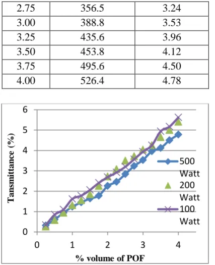
From Table 4 and 5, it is observed that light transmittance varied from 0.34% to 5.62% for 100W light source, from 0.26% to 5.40% for 200W light source and 0.32% to 4.78% for 500W light source. Fig. 8 shows almost linear the relationship in transmittance % of light with corresponding % of POFs.
Compressive strength
Compressive strength of concrete for mix proportion of 1: 1.5: 3 with water cement ratio 0.45 and mix proportion 1: 1: 2 with water cement ratio 0.45 were determined. 28 days compressive strength test results of concrete cubes for two mix proportions and volume fraction of POF varying 0.25% to 4% are given in Table 6.
Table 5 Light passing characteristic using 500W (11000 lumens) halogen source of light
POF volume
%
halogen light source of 500W (11000 lumens)
transmittance (lumens)
transmittance %
0.25 35.4 0.32
0.50 67.2 0.61
0.75 104.0 0.94
1.00 137.2 1.24
1.25 159.6 1.45
1.50 180.4 1.64
1.75 196.0 1.78
2.00 249.6 2.26
2.25 271.2 2.46
www.ijiset.com
209
2.75 356.5 3.24
3.00 388.8 3.53
3.25 435.6 3.96
3.50 453.8 4.12
3.75 495.6 4.50
4.00 526.4 4.78
Figure 8 various % of light passing for different volume fractions of POF
Compressive strength test results demonstrate that due to incorporation of POF, compressive of concrete reduces, also this reduction in compressive strength of concrete increases due to increase in % of POF. But, inclusion of 4% POF has reduced compressive strength of concrete by about 15.2% and 7% for M20 and M25 grade respectively. This reduction in strength is due to nil strength of POF and poor bond of concrete with POFs. For higher grade of concrete, the reduction in compressive strength is insignificant.
Table 6 Compressive strength of M20 and M25 concrete for various % of POFs
% of POF
Average 28 day compressive strength (N/mmP
2
P
)
M20 M25
0.00 26.3 31.3
0.25 25.1 30.4
0.50 25.2 30.3
0.75 25.5 31.1
1.00 25.6 31.5
1.25 25.8 31.6
1.50 26.1 31.7
1.75 26.6 32.0
2.00 27.0 32.2
2.25 26.3 32.1
2.50 26.0 31.7
2.75 25.5 31.5
3.00 24.8 31.3
3.25 23.9 30.5
3.50 23.2 30.2
3.75 22.9 29.6
4.00 22.3 29.1
CONCLUSIONS
• The light transmittance up to 5.62% was achieved by using 4% plastic optical fibers. This can be further increased and light transmitting concrete can be used efficiently in green buildings. It can ensure natural light inside the buildings throughout the day.
• Based on compressive strength test results, it can be said that strength of higher grade light transmitting concrete is not significantly affected by inclusion of POFs.
• Light transmitting concrete requires skilled labour for its production, as POF should be properly placed in concrete, and special attention is needed while placing concrete, to ensure no damage of POFs.
• Light transmitting concrete can be used in structures to make them architecturally and aesthetically beautiful, as various types of glowing patterns can be made with this concrete.
• Cost of manufacture of light transmitting concrete is also high due to plastic optical fibers used and special care is required during its preparation. But, its cost is fully justified because of its usefulness as eco-friendly, energy efficient, aesthetically beautiful on sustainable ground.
REFERENCES
1. Kashiyani, B. K., Raina, V., Pitroda, J. and Shah, B.K., “A Study on Transparent Concrete: A Novel Architectural Material to Explore Construction Sector”, Int. J. of Engineering and Innovative Technology (IJEIT), 2(8), 2013, pp.83-87.
2. Bhushan, M.N.V.P., Johnson, D., Md. Pasha, A. B. and Prasanthi, K., “Optical Fibres in the Modeling of Translucent Concrete Blocks”, Int. J. 0
1 2 3 4 5 6
0 1 2 3 4
500 Watt 200 Watt 100 Watt
Ta
n
sm
itta
n
ce
(%
)
210
of Engineering Research and Applications (IJERA), 3(3), 2013, pp. 13-17.
3. Juan, S. and Zhi, Z., “Some Progress on Smart Transparent Concrete”, Pacific Science Review, 15 (1), 2013, pp.51-55.
4. Kamdi, A. B., “Transparent Concrete as a green Material for Buildings”, Int. J. of Structural and Civil Engineering Research, 2(3), 2013, pp.172-175.
5. Neha, R. N. and Bhole, S. D., “To evaluate Properties of Translucent Concrete/ Mortar and Their Panels”, Int. J. of Research in Engineering and Technology, 1(7), 2013, pp. 23 - 30.
6. Zhi, Z., Ge Ou, Y. H., Genda, C. and Jinping, O., “Research and Development of Plastic Optical Fiber Based Smart Transparent Concrete”, Proc. of SPIE, 7293, 2009, pp. F-1 to F-6.
7. Momin, A. A., Kadiranaikar, R.B., Vakeel, S. J. and Inamdar, A. A., “Study on Light Transmittance of Concrete using Optical Fibers and Glass Rods”, IOSR J. of Mechanical and Civil Engineering, e-ISSN: 2278-1684, p-ISSN:
2320-334X, PP. 67 - 72 .
8. Ahuja, A., Khalid, M. M. and Tarek, I. Z., “Computational Modeling of Translucent Concrete Panels”, J. of Architectural Engineering, ASCE, 21(2), 2015, DOI: 10.1061.
9. Shanmugavadivul, P.M, Scinduja, V., Sarathivelan, T. and Shudesamithronn, C. V., “An Experimental Study on Light Transmitting Concrete”, 3(11), 2014, NCAMESHE- 2014, JUN-2014, pp. 160 - 163.
10. Jimenaz, M.E. and Fernandez, M.F., “Translucent Concrete Research with Glass, Optical Fiber and Glass Fiber”, Springer international publishing Switzerland, 2014, pp. 111 - 116.
11. Bashbash, B. F., Hajrus, R. M, Doaa F., Wafi, A. and Mamoun, A., “Basics of Light Transmitting Concrete”, Global Adv. Research J. of
Engineering, Technology and Innovation, 2(3), 2013, pp. 76 - 83.
12. Paul, S. and Dutta, A., “Translucent Concrete”, Int. J. of Scientific and Research Publications, 3(10), 2013, pp. 1 - 10.
13. IS: 269-2015 (6P
th
P
Revision). “Ordinary Portland Cement – Specifications”. Bureau of Indian Standards, New Delhi.
14. IS: 4031 (Part 1) - 1996 (2P
nd
P
Revision) (Reaffirmed 2005). “Methods of physical tests for hydraulic cement, Part 1- Determination of fineness by dry sieving”. Bureau of Indian Standards, New Delhi.
15. IS: 4031 (Part 4) - 1988 (1P
st
P
Revision) (Reaffirmed 1995). “Methods of physical tests for hydraulic cement, Part 4- Determination of consistency of standard cement paste”. Bureau of Indian Standards, New Delhi.
16. IS: 4031 (Part 5) - 1988 (1P
st
P
Revision) (Reaffirmed 2005). “Methods of physical tests for hydraulic cement, Part 5- Determination of initial and final setting times”. Bureau of Indian Standards, New Delhi.
17. IS: 4031 (Part 11) - 1988 (1P
st
P
Revision) (Reaffirmed 1995). “Methods of physical tests for hydraulic cement, Part 11 - Determination of density”. Bureau of Indian Standards, New Delhi. 18. IS: 2386 (Part 3) - 1963 (Reaffirmed 1997).
“Methods of test for aggregates for concrete – Part III Specific gravity, density, voids, absorption and bulking”. Bureau of Indian Standards, New Delhi. 19. IS: 456 - 2000 (4P
th
P