Invariance-Based Concurrent Error Detection for
Advanced Encryption Standard
Xiaofei Guo and Ramesh Karri
Polytechnic Institute of New York University
[email protected], [email protected]
Abstract. Naturally occurring and maliciously injected faults reduce the reliability of Advanced Encryption Stan-dard (AES) and may leak confidential information. We developed an invariance-based concurrent error detection (CED) scheme which is independent of the implementation of AES encryption/decryption. Additionally, we im-prove the security of our scheme with Randomized CED Round Insertion and adaptive checking. Experimental results show that the invariance-based CED scheme detects all single-bit, all single-byte fault, and 99.99999997% of burst faults. The area and delay overheads of this scheme are compared with those of previously reported CED schemes on two Xilinx Virtex FPGAs. The hardware overhead is in the 13.2-27.3% range and the throughput is between 1.8-42.2Gbps depending on the AES architecture, FPGA family, and the detection latency. One can im-plement our scheme in many ways; designers can trade off performance, reliability, and security according to the available resources.
1
Introduction
The Advanced Encryption Standard (AES) is used in a variety of applications, including smart cards, mobile phones, WWW servers, automated teller machines, and digital recorders. The decreasing cost of VLSI chips and increasing user throughput requirements make hardware implementation of AES necessary.
Faults that occur in VLSI chips are classified into two categories: transient faults that eventually die away and permanent faults. The origin of these faults could be internal phenomena in the system, such as threshold changes, shorts, opens, etc., or external influences, such as electromagnetic radiation. These faults affect the memory as well as the combinational parts of a circuit and are detected using concurrent error detection (CED) [13]. Cryptographic chips are sensitive to natural faults in the hardware [2]. A small number of excited faults can cause a large number of output bits of AES to be faulty [1]. Recently, attackers have injected faults into cryptographic circuits to steal secret information as well [9, 10].
1.1 Related Work
Previous work on CED can be classified into four types of redundancy: hardware, time, information, and combined redundancy.
Hardware redundancyduplicates the function and detects faults by comparing the outputs of two copies. Time redundancy: The function is computed twice on the same input and the results are compared. A variation of the time redundancy is in [7]. The function is computed on both clock edges. This speeds up the computation. Under some conditions, this scheme allows the encryption to be computed twice without affecting the global throughput. This scheme is complex and delicate to implement as technology scales.
of its implementation. All these parity schemes share the same limitation. If an even number of faults occur in the same byte, none of these schemes can detect them.
Combined redundancy: In [4], the authors consider CED at the operation, round, and algorithm levels for AES. In these schemes, an operation, a round, or the entire encryption and decryption are followed by their inverses, and the results are compared with the original input to detect faults. Although these schemes detect most of the faults, they require both encryption/decryption to be on chip and can suffer from more than 100% throughput overhead.
1.2 Contributions
We propose a low overhead, implementation independent, and invariance-based CED scheme, which uses combined redundancy for obtaining a reliable AES implementation. The scheme achieves a fault detection capability that is close to [4] and hardware redundancy, the state-of-the-art countermeasures, but with much lower cost. Our contributions are as follows:
– We present the invariance-based1CED with Randomized CED Round Insertion and adaptive checking for AES to improve security.
– We prove that the invariance-based CED scheme detects all single-bit and single-byte faults.
– The invariance-based CED achieves an order of105lower fault miss rate than the best parity schemes for multiple burst and multiple random faults.
This paper is organized as follows: In Section 2, we introduce the AES algorithm. In Section 3, we propose the key idea of our invariance-based CED scheme, and we show the fault coverage, hardware overhead, and detailed analyses of the scheme.
2
Advanced Encryption Standard
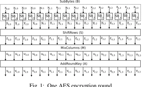
In this paper, we consider 128-bit AES as specified by the National Institute of Standards and Technology (NIST). AES encrypts a 128-bit input plaintext into a 128-bit output ciphertext with a user key using 10 nearly identical rounds plus an initial special round (round 0). One AES encryption round consists of SubBytes, ShiftRows, MixColumns, and AddRoundKey denoted byB,S,M, andA, respectively, as shown in Figure 1. In round 0, only AddRoundKey is performed and in round 10, MixColumns is not performed. Each operation in every round acts on a 128-bit input
state, where each state element is a byte inGF(28). In this paper, each byte is denoted bys
r,c(0≤r, c≤3), and
it indicates that this byte is in rowrand columncin state matrix.
S=
s0,0s0,1s0,2s0,3
s1,0s1,1s1,2s1,3
s2,0s2,1s2,2s2,3
s3,0s3,1s3,2s3,3
= [sr,c]3r,c=0 (1)
In SubBytes, all the bytes are processed separately by 16 S-boxes (SBs). Each S-box performs a nonlinear trans-formation of the input byte. LetX be the input to the SBs. The resulting output is:
Y =B(X) = [yr,c]3r,c=0 (2)
In ShiftRows, the rows of the state are shifted cyclically byte-wise using a different offset for each row. Row 0 is not shifted, while rows 1, 2, and 3 are cyclically shifted to the left by 1 byte, 2 bytes, and 3 bytes, respectively. The resulting output is:
Z =S(Y) =
y0,0y0,1y0,2y0,3
y1,1y1,2y1,3y1,0
y2,2y2,3y2,0y2,1
y3,3y3,0y3,1y3,2
Fig. 1: One AES encryption round
= [yr,(r+c)mod4]3r,c=0= [zr,c]3r,c=0 (3) In MixColumns, the output state is obtained by multiplying a constant matrix with the output of ShiftRows. The resulting output is:
U =M(Z) =
02 03 01 01 01 02 03 01 01 01 02 03 03 01 01 02
z0,0z0,1z0,2z0,3
z1,0z1,1z1,2z1,3
z2,0z2,1z2,2z2,3
z3,0z3,1z3,2z3,3
= [ur,c]3r,c=0 (4)
In AddRoundKey, the input state is added (modulo-2) to the round key, i.e., the 128-bit stateU with matrixK = [kr,c]3r,c=0. The resulting output is:
V =A(K)U = [ur,c]3r,c=0+ [kr,c]3r,c=0= [vr,c]3r,c=0 (5)
3
Invariances of AES
In [5], the authors have shown that AES exhibits various mapping invariance properties. They were investigating these as possible source of weakness in AES. In contrast, we use these invariances for CED to protect the AES against random faults and malicious attacks. We analyze three round level invariances of AES. We give a formal proof of the invariance propertyP1, which is the most effective invariance according to our experimental results. We analyze the effectiveness of the remaining invariances in Section 4.
Theorem 1. An AES round can be represented as
A(K)(M(S(B(X))))
where X is the 128-bit input to the round. Exist byte permutation P, so that the following hold true:
A(K)(M(S(B(X)))) =P−1(A(P(K))(M(S(B(P(X)))))) (6)
whereP−1denotes the inverse function ofP.
One of the byte permutation is:
P1(X) =P1([xr,c]3r,c=0) =
x0,3x0,0x0,1x0,2
x1,3x1,0x1,1x1,2
x2,3x2,0x2,1x2,2
x3,3x3,0x3,1x3,2
= [xr,(c+3)mod4]3r,c=0 (7)
Proof. Let us start from the right-hand side of the equation. First, we apply permuted inputX0 =P1(X)to SubBytes, and from (2) and (7), we get:
Y0 = [yr,c0 ]3r,c=0= [yr,(c+3)mod4]3r,c=0=P1(Y) (9)
GivenY0 as the input to ShiftRows, we get:
Z0 =S(Y0) =
y00,0y00,1y00,2y00,3 y10,1y01,2y01,3y10,0 y20,2y02,3y02,0y20,1 y30,3y03,0y03,1y30,2
=
y0,3y0,0y0,1y0,2
y1,0y1,1y1,2y1,3
y2,1y2,2y2,3y2,0
y3,2y3,3y3,0y3,1
= [zr,c0 ]3r,c=0 (10)
From (3) and (10), we find that:
Z0 = [zr,(c+3)mod4]3r,c=0=P1(Z) (11)
ApplyingZ0 to MixColumns, we get:
U0 =
02 03 01 01 01 02 03 01 01 01 02 03 03 01 01 02
z00,3z
0
0,0z
0
0,1z
0
0,2
z10,3z10,0z01,1z10,2 z20,3z20,0z02,1z20,2 z30,3z30,0z03,1z30,2
= [ur,(c+3)mod4]3r,c=0=P1(U) (12)
Then we apply the permuted round key matrixK0 =P1(K)resulting in:
V0 = [u0r,c]
3
r,c=0+ [k
0 r,c]
3
r,c=0
= [ur,(c+3)mod4]3r,c=0+ [kr,(c+3)mod4]3r,c=0=P1(V) (13)
Finally we apply inverse permutationP−1to the output. We get:
P1−1(V0) =P1−1(P1(V)) =V (14)
3.1 Invariance-based CED Architecture
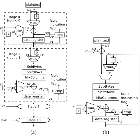
We design two invariance-based CED architectures for AES: Fully pipelined and iterative.
Fully pipelined: There are 11 stages in our pipelined architecture. For each pipeline stage in Figure 2(a), we add two muxes (muxxandmuxk) and a comparator (cmp).P is a permutation of wires based on the invariance property.
P−1 is the inverse permutation. We need two encryption cycles to detect the faults, and let us call them C1 and C2. In C1, let the input and the key of round 1 beX1andK1. We run the encryption withmuxxandmuxk, selecting
X1andK1as the inputs. The round resultV1is stored in the data register. Then we run C2; we run the encryption withmuxxandmuxk, selecting permuted inputsX1
0
(a) (b)
Fig. 2: AES hardware architectures (a) Pipeline. (b) Iterative. cmp stands for comparator. We assume that the compara-tor is fault tolerant.
Iterative: As shown in Figure 2(b), we addmuxxandmuxk and a comparator. There is one security benefit of
iterative implementation. Each ciphertext takes 10 cycles to generate in an iterative architecture. If the designer chooses to add a C2 for every ten cycles, then the faulty ciphertext will not be sent to the output because the fault is detected before it is generated. This will further prevent an attacker from stealing the secret key. In the pipeline architecture, a ciphertext is generated every cycle. Therefore, if the faults are generated before the comparison, faulty outputs will be obtained by the attacker.
3.2 Fault Analysis
Invarianced-based CED detects all single-bit and single-byte faults. Our simulations show that this CED scheme detects 99.99999997% of multiple burst faults and close to 100% of multiple random faults. Fault coverage (FC) is calculated as:
F C= 1−F M R
where FMR is the fault miss rate calculated as:
F M R= Tundetected
Ttotal−Tcorrect
whereTundetectedis the number of tests in which faults are excited but not detected.Ttotalis the total number of tests
we applied.Tcorrectrepresents the tests in which the faults are not excited.
100% Fault Coverage of Single-Bit Faults
Theorem 2. If a single-bit fault in any of the steps in a round affects the outputs of the final result of that round, our scheme will detect it.
Proof. Case 1: A single-bit fault in S-box (SB). In Figure 1, let theSBi,j(0 ≤i, j ≤3) have a single-bit stuck-at
0 1×10⁵
2×10⁵ 3×10⁵ 4×10⁵ 5×10⁵ 6×10⁵ 7×10⁵ Number of burst faults injected
10-10 10-9 10-8 10-7 10-6 10-5 10-4 10-3 10-2 10-1
Fault miss rate
Parity [7] for MixColumns and AddRoundKey Parity [7] for SubBytes and ShiftRows Invariance-based CED (P1)
Fig. 3: Simulation results show that the fault miss rate of the invariance-based CED is superior to that of the parity scheme in [6].
In C1, theSBi,j generates faulty outputyi,j. After ShiftRows, the outputs are[zr,c]3r,c=0 =[yr,(r+c)mod4]3r,c=0, and the faulty state element iszi,(j−i)mod4 = yi,j. In MixColumns, a single faulty input causes four bytes within
the same column to be faulty. The faulty state elements are represented as[ur,(j−i)mod4]3r=0. After AddRoundKey, [vr,(j−i)mod4]3r=0are the faulty state elements. In C2, we applyX
0
andK0 as the permuted inputs. Using the same steps shown above, faulty state elements are represented as[v0r,(j−i)mod4]3
r=0. From (8), we know that
[v0r,(j−i)mod4]3r=0= [vr,((j−i)+3mod4)mod4]3r=0
Therefore, the faulty column in C1 is(j−i)mod4, but the faulty column in C2 corresponds to column((j−i)mod4)+ 3)mod4in C1; note that0≤i, j≤3and(j−i)mod46= (((j−i)mod4) + 3)mod4.
Since faultySBi,jaffects different columns in C1 and C2, we always compare a faulty column with a nonfaulty
column, and our scheme detects the fault as long as it affects the output. For a concrete example, letSB1,2be faulty, thus,y1,2 is the faulty output byte. After ShiftRows,z1,1 = y1,2. After MixColumns, the faulty state elements are
shown as[ur,1]3r=0. Then we apply this as the input of AddRoundKey, so faulty state elements are shown as[vr,1]3r=0. Then we run C2, and faulty state elements are represented as [vr,01]3
r=0. Because[v
0
r,1]3r=0 = [vr,0]3r=0, the faulty columns in C1 and C2 are different, and we detect the fault by comparing the outputs.
Case 2: A single-bit fault in ShiftRows. A fault in ShiftRows is equivalent to a fault at the input of MixColumns, and thus, we prove this in case 3.
Case 3: A single-bit fault in MixColumns. Since MixColumns is mainly implemented with XOR and a few other basic gates, we consider a fault in MixColumns in three scenarios: the input, the internal logic gates, and the output. If there is a stuck-at fault in the input, the fault will propagate to all four bytes in the same column. Assuming that column [ur,j]3r=0is faulty in C1, we know that the column[vr,j]3r=0is faulty in the final output of the current round. In C2, we know that the column[u0r,j]3
r=0is faulty, and the column[v
0
r,j]3r=0of the output of the round is also faulty. From (12) and (14), we know thatj0 = (j+ 3)mod4. Because the faulty columns of the two outputs are different, we detect the fault.
Case 4: A single-bit fault in AddRoundKey.AddRoundKey is mainly implemented as bit-wise XOR gates. We consider a fault in AddRoundKey as stuck-at fault in the input or output. The fault at the input is equivalent to the fault in the output of MixColumns. Let us prove the theorem true for a single-bit fault at the output of AddRoundKey. Let the faulty bit affects bytevi,jin the C1 andv
0
i,jin C2. From (14), we know thatv 0
i,j =vi,(j+3)mod4. Again, the faulty
columns in C1 and C2 are different, and thus we detect the fault.
Table 1: Comparison of fault coverage. a. burst faults b. random faults
FDS Fault coverage
Single bit Single byte Multiple bit
HW red. 100% 100% 100%
Parity 1 [1] 100% 50% 99.997% Parity 2 [15] 98.7% 50% 48-53% Parity 3 [6] 100% 50% 99.996% Alg. level [4] 100% 100% 100%
Invariance 100% 100% 99.99999997%a
100%b
radiation [12] to inject faults, this is a realistic attack model. We define single-byte fault as faults that affect at most a single byte, i.e., they can affect from one bit upto eight bit of the byte.
Theorem 3. If multiple faults in any of the processing steps in a round affect a byte quantity, the invariance scheme will detect it.
Proof. We prove this theorem for single-byte fault in either S-box, ShiftRows, MixColumns, or AddRoundKey.
Case 1: A single-byte fault in S-box (SB). Let multiple faults in S-box affect one byte outputyi,j in C1. From
the proof of our theorem 1, after AddRoundKey, faulty state elements are shown as[vr,(j−i)mod4]3r=0. After C2, the faulty state elements are represented as[v0r,(j−i)mod4]3
r=0. Theorem 1 proves that these faults are detected. A single-byte fault in ShiftRows, MixColumns, and AddRoundKey can also be similarly detected.
In order to have a 100% single-byte fault detection rate, one need hardware redundancy or combined redundancy [4], both of which have more than 100% hardware overhead. Our fault simulation confirms that the invariance-based CED detects all single-bit and single-byte faults.
Fault Coverage for Multiple Faults We simulated multiple faults for the invariance scheme and compared it with the one proposed in [6]. These models cover both natural faults and fault attacks [3].
Due to technology constraints, an attacker may not be able to inject a single-bit fault [3]. Multiple faults are actually injected in the process. We use burst and random fault models [3]. We use Fibonacci Linear Feedback Shift Register (LFSR) with 128-bit output taps to inject faults. The maximum sequence length polynomial for the LFSR is selected asL(X) =X128+X29+X27+X2+ 1.
Burst faultsoccur at the output of only one operation at a time, i.e., the faults are injected at the 128-bit output of one operation in the AES encryption. This includes both stuck-at zero and one faults. The size, location, and type of the burst are randomly generated.
The results of our simulations for the burst faults in the AES encryption are shown in Figure 3. We compare our miss rate with that of [6]. The dot-dash line respresents the fault miss rate of SubBytes and ShiftRows in the AES encryption in [6]. The dash line represents the fault miss rate of MixColumns and AddRoundKey in the AES encryption in [6]. The solid line represents the fault miss rate of the invariance-based CED. We have injected up to 700,000 burst faults at the operation outputs and monitored the faults that are detected by the fault indication flag. The fault miss rate for [6] is between10−2and10−3. The miss rate of our scheme is between10−7and10−8; a reduction of105.
Random faultsare injected at random locations, i.e., four 128-bit outputs of the operations. In another simulation, we saw 0% fault miss rate after injecting up to 700,000 random faults.
Table 2: Comparisons of implementation of CED schemes on two Xilinx FPGAs. We use the metrics, FPGA platform, and results from [6]. Our pipeline implementation are shown in bold, and we implement the iterative architectures. a. the latency is 2x the original AES encryption/decryption b. using two (256×9) ditributed memories for CED of each S-box or inverse S-box c. using (256×9) distributed memories for CED of each S-box or inverse S-box d. checking ratio is 11 e. checking ratio is 10 f. checking ratio is 1
FPGA
Encryption Decryption
Arch. Scheme Slice Freq. Thro. Eff(Mbps Slice Freq. Thro. Eff.(Mbps (Device) (overhead) (MHz) (Gbps) /slice) (overhead) (MHz) (Gbps) /slice)
V
ir
tex
T
M
-4
(xc4vlx160-12)
Pipe.
Original 18335(-) 240.5 30.8 1.7 19322(-) 203.5 26.0 1.3 HW Red. 36684(100.1%) 240.5 30.8 1.1 38658(100.1%) 203.5 26.0 0.7 Parity 1 [1]b 39104(113.3%) 163.5 20.9 0.5 40244(108.3%) 145.4 18.6 0.5 Parity 2 [15]c 21211(15.7%) 240.5 30.8 1.4 22280(15.3%) 203.5 26.0 1.1 Parity 3 [6] 20127(9.8%) 240.5 30.8 1.5 20909(8.2%) 203.5 26.0 1.2 Alg. level [4]38273(108.7% [6]) 194.9 24.9
a 0.6 38273(98.1% [6]) 194.9 24.9a 0.6
(1.6%) (1.6%)
Invariance 21253(15.9%) 232.3 27.2d
–14.9f1.28d
–0.7f 22240(15.1%) 197.6 23.1d
–12.6f 1.0d
–0.6f
Iter. Original 1905(-) 224.6 2.9 1.5 2002(-) 192.0 2.5 1.2
Invariance 2170(13.9%) 217.4 2.55e–1.4f 1.2e–0.7f 2267(13.2%) 186.7 2.2e–1.2f 1.0e–0.6f
V
ir
tex
T
M
-5
(xc5vlx110-3)
Pipe.
Original 2960(-) 371.7 47.6 16.1 3906(-) 296.3 37.9 9.7 HW Red. 5934(100.5%) 371.7 47.6 10.2 7826(100.4%) 296.3 37.9 5.5 Parity 1 [1]b 5590(88.9%) 282.8 36.2 6.5 6680(71.2%) 260.2 33.3 4.9 Parity 2 [15]c 3619(22.3%) 304.0 38.9 10.7 4426(13.3%) 277.0 35.5 8.0 Parity 3 [6] 3757(26.9%) 371.7 47.6 12.7 4286(9.7%) 296.3 37.9 8.8 Alg. level [4] 5849(97.6% [6]) 284.4 36.4
a 6.2 5849(49.7% [6]) 284.4 36.4 6.2
(-14.8%) (-14.8%)
Invariance 3664(23.9%) 358.9 42.2d–23.0f12.0d–6.6f 4434(13.5%) 288.9 33.9d–18.5f 7.6d–4.2f
Iter. Original 344(-) 347.0 4.4 12.8 462(-) 286.4 3.7 7.9
Invariance 438(27.3%) 335.8 3.9e
–2.2f 7.9e
–4.4f 539(16.7%) 273.1 3.2e
–1.8f 5.9e
–3.7f
explored by varying the checking ratioR, which is the ratio of the number of results computed without invariance to the number of results computed with invariance-based CED.
3.3 Security Analysis
In this section, we propose two policies that the designers can employ to further secure their design.
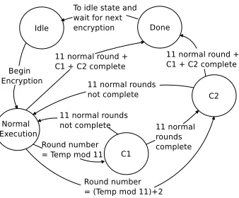
Randomized control:The invariance-based CED technique cannot detect the faults that are not excited in C1 and C2 rounds. If an attacker determines the architecture of the AES with the proposed CED implementation, this feature can be used as a weakness to insert faults in such a way that they do not exist during the CED rounds but only during the normal rounds. To prevent this, we proposed using Randomized CED Round Insertion (RCRI). In this method, the positions of the CED rounds C1 and C2 are randomized during the 11-round AES encryption process for pipelined architecture. This can be implemented as shown in the state diagram of Figure 4. A random number can be obtained using the randomness property of the AES algorithm.
Fig. 4: State machine for Randomized CED Round Insertion (RCRI)
lookup table which contains modulo 11 results from input 0 to 15. For the iterative architecture, since the encryption takes 10 rounds, we use Temp modulo 10.
Adaptive checking:If the designer choosesR 6= 1, some of the transient faults injected by the attacker may go undetected. However, an attacker needs to obtain a large number of faulty outputs to steal the secret key. We suggest the designer deploy an adaptive approach. When a fault is detected, the chip changes its checking ratio from theR
specified by the designer to 1, and thus almost all the faults will be detected. If faults are detected in a number of consecutive checks, the chip can stop its function or self-destruct.
IfR = 1, all results will be checked. The fault miss rate remains the same for permanent and transient faults. If
R > 1, everyRthresult will be checked. Let us assume the transient faults appear forN cycles. WhenR ≤N, the
fault coverage remains the same, because the results of C1 and C2 will be checked before the faults disappear. When
R > N, the probability of detecting a single-bit and single-byte fault is NR ×100%and that of multiple burst faults is
N
R ×99.99999997%.
3.4 Implementation and Comparison
The implementation results shown in Table 2 are all post place-and-route. We implement fully pipelined and iterative architectures. We use pipelined distributed memories for S-boxes and inverse S-boxes similar to [6]. Hardware redun-dancy, information redundancy [1, 6, 15], combined redundancy [4], and invariance-based CED are compared. The metrics include (1) slice utilization (the number of occupied slices), (2) slice overhead (ratio of number of slices for CED schemes over the number of slices for AES), (3) maximum clock frequency, (4) throughput, and (5) efficiency (raitio of (4) over (1)).
5 10 15 20 25 30 Number of faults injected
10-8 10-7 10-6 10-5 10-4 10-3 10-2
Fault miss rate
Invariance P1, P3 Invariance P2
Fig. 5: Fault miss rate for invarianceP1,P2, andP3
of [4] is in the 49.7–108.7% range [6], e.g., 108.7% for AES encryption on Virtex-4 FPGA. If both encryption and decryption are on the same chip, the hardware overhead of [4], which is from the comparator, is very low. For Virtex-5, the overhead of this scheme is -14.8%, because the slice utilization of this scheme is smaller than the total slice utilization of encryption and decryption. However, the efficiency of the invariance-based CED is higher than that of [4]. Most importantly, the invariance-based CED and all other CED schemes do not require both encryption and decryption to be on chip.
For iterative architecture, since round 0 is performed in the same clock cycle as round 1, an extra delay is added in the critical path. The hardware overhead of the invariance-based CED as a 16.7-27.3% is slightly higher than that of the pipeline architecture on Virtex-5.
4
Concluding Remarks
There are several other mapping invariances that can be used for CED [5]. Most of them restrict the pattern of the inputs and thus are not effective when realistic random inputs are provided. However, there are two other invariances that allow us to perform CED on any inputs:
P2(X) =
x0,2x0,3x0,0x0,1
x1,2x1,3x1,0x1,1
x2,2x2,3x2,0x2,1
x3,2x3,3x3,0x3,1
(15)
P3=P1(Ppre(X)) =P1(
x0,0x0,3x0,2x0,1
x1,0x1,3x1,2x1,1
x2,0x2,3x2,2x2,1
x3,0x3,3x3,2x3,1
) (16)
P2 swaps the first and third columns and also the second and fourth columns in the state matrix.P3is the same asP1except that the initial inputX is permuted byPprebefore being applied to the input. Fault miss rate for CED
using invariancesP1,P2, andP3are compared in Figure 5. The fault miss rate dropped sharply to below10−7after we injected 11 faults usingP1andP3, and 15 faults forP2. After we injected 15 faults, the fault miss rate was very low and thus not shown in Figure 5. The fault miss rates of invarianceP1andP3are lower than the fault miss rate of invariance
P2with any number of faults injected. Compare toP2, the area and performance overheads ofP1is the same. ForP3, one first need to applyPpre(X)as input to run C1, and store the resultVpre. Then useP1(Ppre(X))as input to run C2,
and applyP1−1to the resultVpre0 to compare withVpre. Both C1 and C2 are extra overhead for performance. Compare
5
Acknowledgments
This material is based upon work supported by the NSF CNS program under grant 0831349.
References
1. Guido Bertoni, Luca Breveglieri, Israel Koren, Paolo Maistri, and Vincenzo Piuri. Error Analysis and Detection Procedures for a Hardware Implementation of the Advanced Encryption Standard.IEEE Trans. Computers, 52(4):492–505, 2003.
2. D. Boneh, R. DeMillo, and R. Lipton. On the Importance of Checking Cryptographic Protocols for Faults. InEurocrypt, pages 37 – 51. Lecture Notes in Computer Science, 1997.
3. Luca Breveglieri, Israel Koren, and Paolo Maistri. An Operation-Centered Approach to Fault Detection in Symmetric Cryptog-raphy Ciphers.IEEE Trans. Computers, 56:635–649, May 2007.
4. Ramesh Karri, Kaijie Wu, Piyush Mishra, and Yongkook Kim. Concurrent Error Detection of Fault-Based Side-Channel Cryptanalysis of 128-Bit Symmetric Block Ciphers. InDAC, pages 579–585, 2001.
5. Tri Van Le, Rudiger Sparr, Ralph Wernsdorf, and Yvo Desmedt. Complementation-Like and Cyclic Properties of AES Round Functions. InAES, pages 128–141, 2005.
6. M. Mozaffari-Kermani and A. Reyhani-Masoleh. Concurrent Structure-Independent Fault Detection Schemes for the Advanced Encryption Standard.IEEE Trans. Computers, 59(5):608–622, 2010.
7. P. Maistri and R. Leveugle. Double-Data-Rate Computation as a Countermeasure against Fault Analysis. IEEE Trans. on Computers, 57(11):1528–1539, Nov 2008.
8. Mehran Mozaffari-Kermani and Arash Reyhani-Masoleh. A Lightweight High-Performance Fault Detection Scheme for the Advanced Encryption Standard Using Composite Field.IEEE Trans. VLSI Systems, 19(1):85–91, 2011.
9. G. Letourneux P. Dusart and O. Vivolo. Differential Fault Analysis on AES. InCryptology ePrint Archive, 2003.
10. G. Piret and J.J. Quisquater. A Differential Fault Attack Technique against SPN Structures, with Application to the AES and Khazad. InCHES, pages 77–88, Sept 2003.
11. R.A. Reed, M.A. Carts, P.W. Marshall, C.J. Marshall, O. Musseau, P.J. McNulty, D.R. Roth, S. Buchner, J. Melinger, and T. Corbiere. Heavy Ion and Proton Induced Single Event Multiple Upsets.IEEE Trans. on Nuclear Science, 44(6):2224–2229, 1997.
12. David Samyde, Sergei Skorobogatov, Ross Anderson, and Jean-Jacques Quisquater. On a New Way to Read Data from Memory. Inproceedings of IEEE Security in Storage Workshop, pages 65–69, Dec 2002.
13. Daniel P. Siewiorek and Robert S. Swarz. Reliable Computer Systems: Design and Evaluation. A K Peters/CRC Press; 3 edition, 1998.
14. Sergei P. Skorobogatov and Ross J. Anderson. Optical Fault Induction Attacks. Inproceedings of CHES, pages 2–12, Aug 2002.
![Fig. 3: Simulation results show that the fault miss rate of the invariance-based CED is superior to that of the parityscheme in [6].](https://thumb-us.123doks.com/thumbv2/123dok_us/7901170.1311610/6.612.199.416.82.242/fig-simulation-results-fault-invariance-based-superior-parityscheme.webp)
![Table 2: Comparisons of implementation of CED schemes on two Xilinx FPGAs. We use the metrics, FPGA platform,and results from [6]](https://thumb-us.123doks.com/thumbv2/123dok_us/7901170.1311610/8.612.73.540.155.432/table-comparisons-implementation-schemes-xilinx-metrics-platform-results.webp)