Concentrated Solar Power: Components and materials
A. Kribus
School of Mechanical Engineering, Tel Aviv University - Tel Aviv 69978, Israel
Summary. — CSP technologies are well developed and offer many advantages compared to other renewable energy options. They can also be very effective in many locations with high solar radiation around the world. However today they are less competitive than other technologies. Understanding the limitations, and identifying opportunities for improvements, requires a detailed analysis of the energy conversion processes, the needed components, and the required technologies for these plant components. Here we present the three main energy conversion steps in a CSP plant, the behavior and limitations of the technologies that are currently used in commercial CSP plants, and some directions for development of plant components that will offer better performance.
1. – Energy conversion efficiency
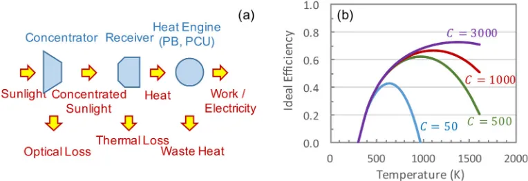
Fig. 1. – (a) Schematic of main energy conversion steps. (b) Ideal plant efficiency as a function of concentration ratio and receiver temperature.
The overall plant efficiency η can be expressed as a product of several subsystem efficiencies, corresponding to the sequence of steps that occur during the process of converting sunlight to electricity, as shown in fig. 1(a):
η(C, Trec) =ηopt(C)·ηrec(C, Trec)·ηP B(Trec). (1)
ηopt is the optical efficiency: the fraction of the solar radiation collected by the
concen-trator field that actually enters the receiver aperture. ηrec is the receiver efficiency, the fraction of radiation power entering the receiver that exits as thermal energy in the fluid stream. ηP B is the power block efficiency, which represents actually two conversions: the
conversion of thermal energy in the fluid to mechanical energy by the heat engine, and conversion of the mechanical energy to electrical energy by the generator. These sub-system efficiencies depend on the concentration ratioCand on the receiver temperature
Trec. For simplicity, we assume that the receiver temperature is uniform (although in
real receivers there is a temperature distribution and this affects their efficiency), and that the fluid provided by the receiver to the power block is at the receiver temperature (again not always accurate in realistic systems).
the flux of direct sunlight. The ideal receiver efficiency is then
ηrec(C, T) = 1−σ
(Trec4 −Tamb4 )
CI .
(2)
The ideal power block includes the best possible heat engine,i.e., an engine operating at Carnot efficiency; and an ideal generator with efficiency 1:
ηP B(C, T) = 1−TTamb
rec .
(3)
Combining all three ideal subsystems, the overall plant efficiency is then:
η(C, T) =
1−σ(T
4
rec−Tamb4 )
CI 1−
Tamb Trec
.
(4)
The ideal plant efficiency is shown in fig. 1(b) as a function of receiver temperature for several levels of concentration [1]. C= 50 is representative of linear concentrators such as the parabolic trough and Linear Fresnel, C = 500 and C = 1000 are representative of solar towers, and C = 3000 can be achieved in a parabolic dish or a tower with secondary concentration. For each concentration, there is an optimal temperature, rep-resenting the best compromise between the thermal emission loss of the receiver and the thermodynamic loss of the heat engine. As the concentration increases, the maximum ideal efficiency increases, and the temperature required to achieve the optimum increases as well.
Real plants to not reach these ideal values, but they do follow the general trends shown in fig. 1(b). Therefore, technologies that enable increase in operating temperature and concentration have a good potential of increasing the plant conversion efficiency. It should be noted that such technologies may lead also to increase in plant installed cost, and therefore the overall impact of such advanced technologies on the levelized cost of energy should be investigated carefully.
2. – Optical performance
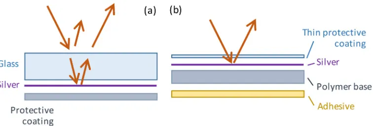
Fig. 2. – Schematic structure of mirrors: (a) back-surface silver on glass, (b) front surface on polymer.
solution requires curving of the glass at high accuracy, which can be done by thermal sagging (for short focal lengths) or elastic deformation (for long focal lengths), and can be expensive for both options. Thin glass (<1 mm) with the same back silver coating is easier to curve and offers higher reflectivity (>95%), but such glasses are fragile and difficult to handle.
Several front-surface reflector systems have been proposed as alternatives to glass-based reflectors. One uses an enhanced aluminum or aluminum/silver coating on a polished aluminum substrate, with a top protective layer of anodization or polymer. However, these mirrors suffer from degradation and are not suitable for field deploy-ment. Another solution is based on a polymer substrate coated with silver and protected by poly(methyl methacrylate) (PMMA), a transparent weather-resistant acrylic, and with a back adhesive for attaching to a substrate. The geometric shape of the mirror can be formed with a metal substrate, which is easier compared to bending glass, and also can provide structural rigidity after curving. These mirrors show promise, and some manufacturers claim to have achieved the needed high reflectivity (> 93%) and dura-bility (>30 years in accelerated testing) to replace the reliable old solution of a glass back-surface reflector [2]. However, other evaluations are more skeptical [3], and most commercial CSP plants continue to use glass mirrors.
2.2.Geometric losses. – This category includes several effects related to the geometry of the concentrators. The geometric inaccuracy in the manufacturing and assembly of the optical surfaces may cause some of the reflected radiation to miss the receiver aperture, a loss often called “spillage”. Misalignment of the concentrator due to finite accuracy of the tracking mechanism can also cause spillage. Practical concentrators need to be very accurate, but the high cost of achieving very high accuracy leads to a compromise where some spillage is allowed.
Fig. 3. – Schematic of the effect of incidence angle on the effective collection area of a parabolic trough.
where A is the collector aperture area, and θ is the incidence angle on the collector aperture (shown in fig. 3 for a typical geometry of a parabolic trough). As the incidence angle increases, the amount of collected power is decreased. This is often called the “cosine loss”.
In a field of many concentrator units, mutual shading among neighboring units may cause a loss of incident radiation. In heliostat fields, the reflected radiation may be lost also on its way from the heliostat to the tower, and this is called a blocking loss. These losses vary in time due to the apparent motion of the sun. Shading and blocking losses can be reduced by increasing the distances among the concentrator units in the field, as can be seen in the heliostat field of fig. 4. This typically leads to a ratio of concentrator area to land area of up to 1:4, which means poor use of available land area.
Fig. 4. – PS10 heliostat field and tower, and part of PS20 field, near Seville, Spain (credit: ´
The design of concentrator fields and the optimization of the concentrators’ geometry are usually performed with sophisticated optical simulation software [4]. Typical con-centration values in practice are 30–80 for linear concentrators (trough, linear Fresnel) and 300–1,000 for point-focus devices (tower, parabolic dish). The optical efficiency for large scale concentrators is usually in the range of 60–75%, when averaged over annual operation (recall that some of the optical losses vary with time due to the apparent mo-tion of the sun). An excepmo-tion is the parabolic dish, which can achieve higher efficiency of>85% and high concentration ratios even in large-scale industrial plants.
3. – Receiver performance
3.1.Tubular receivers. – The most common CSP receiver is a metal tube, illuminated by the concentrated solar radiation, with internal flow of a heat transfer fluid (HTF) to be heated. The energy balance of the receiver tube may be expressed in terms of incident vs.lost flux (power per unit external surface area of the tube). The net fluxqnetavailable for heating the internal fluid is
qnet=qin−qref−qem−qconv−qcond,
(5)
qin=C·Iis the incident flux on the receiver. qref =ρrecqinis the flux reflected from the
tube, whereρrecis the total reflectivity of the tube surface. qem =rec σ(Trec4 −Tamb4 ) is the thermal emission loss, whererecis the surface total emissivity. qconv=h(Trec−Tamb) is the convection loss from the exposed surface of the tube to the ambient air, wherehis the effective convection coefficient. qcond=U(Trec−Tamb) is the conduction loss through
any part of the tube surface that is insulated, where U is the heat transfer coefficient. The different loss mechanisms are shown schematically in fig. 5(a).
The receiver efficiency is then:
ηrec= qqnet in
= 1−ρrec−recσ(T
4
rec−Tamb4 ) + (h+U)(Trec−Tamb)
CI .
(6)
Figure 5(b) shows part of a typical tubular receiver for line-focus concentrators, some-times called the heat collection element (HCE). It includes an internal stainless steel pipe with a dark coating on the exterior of the pipe, an external glass pipe that maintains a vacuum around the steel pipe, a bellows at the end of the pipe to compensate for differ-ences in thermal expansion between the glass and the metal, and a getter (not shown) to maintain the vacuum by absorbing gases that permeate into the evacuated space. These features contribute to reduce the various losses and increase the receiver efficiency, as discussed below.
Fig. 5. – (a) Schematic showing the different losses from a tubular receiver; (b) a receiver for a parabolic trough collector (HCE, or vacuum tube).
inner walls of an insulated cavity. The tubes are usually made from a high-temperature-resistant steel or a nickel alloy such as Inconel. The metal is coated with a black coating or paint, but without the additional features of the linear focus receiver such as glass envelope and vacuum.
3.2.Reflection, emission and selective surfaces. – The absorbing surface of the receiver should satisfy multiple requirements: it should absorb as much as possible of the incident solar radiation (low reflectivity); it should emit as little thermal radiation as possible (low emissivity); and it should also have a low convection loss. this combination of requirements is satisfied by two means applied to the receiver tube shown in fig. 5(b). The first is vacuum —an external transparent glass tube encloses the receiver tube, and the space between the tubes is evacuated. In the absence of air, the convection loss from the receiver tube is eliminated: h= 0 in eq. (6).
Fig. 6. – (a) Spectra of sunlight (AM1.5D) and of blackbody emission at 700 K, with the spectral emissivity of an ideally selective absorber surface. (b) Typical structures of Cermet selective coatings.
A typical commercial selective coating provides a high total absorptivity of 0.93– 0.96 for solar radiation, together with a low overall emissivity of about 0.05 at room temperature and 0.1–0.15 at the receiver’s operating temperature of 400–500◦C. Fig-ure 7(b) shows the resulting efficiency of a typical parabolic trough receiver: from the measurement of the overall efficiency from sunlight to heat, and a separate measurement of the optical efficiency, the receiver efficiency can be identified and it is 95% at receiver temperature of 350◦C, declining to 83% at 500◦C.
The main limitation of the selective coatings is stability at high temperature, partic-ularly if the coating is exposed to air, and they tend to fail if the vacuum in the HCE is breached. Efforts are ongoing to develop high-temperature air stable coatings, however the solutions found so far contain relatively expensive materials and are not yet practical for commercial applications [6].
TableI. –Typical power block efficiencies in steam plants as a function of operating temperature and pressure.
Temperature (C) Pressure (bar) Efficiency
400 100 32%
530 170 37%
590 250 45%
4. – Heat engine efficiency
The two most common power conversion cycles in conventional power plants are the steam-based Rankine cycle and the air-based open Brayton cycle (also called the gas turbine cycle). In both cycles, mechanical power is produced by manipulation of pressure and temperature of the working fluid: water or air. A detailed description of the operation of these standard cycles can be found in many thermodynamics textbooks. A combination of these two cycles, the combined cycle (CC), uses the hot exhaust stream from the gas turbine to generate the steam for the Rankine cycle, thus exploiting a larger fraction of the heat input and reaching a higher efficiency. Currently, only the steam cycle is used in CSP plants, although much effort has been invested in developing solar technology for gas turbines as well.
The conversion efficiency of the heat engine (or the power block, containing also the generator attached to the heat engine) depends on the operating temperature. Higher temperature leads in general to higher efficiency, consistent with the ideal limit of Carnot efficiency discussed above. The selection of the heat transfer fluid poses limitations on achievable temperature. In most parabolic trough plants today the HTF is a synthetic oil such as Therminol VP-1 that can operate up to 400◦C. The hot HTF is used to generate steam for the power generation cycle in a boiler, and the steam temperature is then limited to less than 400◦C. This leads to relatively low conversion efficiency, as shown in table I. In some tower plants the HTF is a molten salt (mixture of NaNO3 and KNO3) that allows a higher temperature of about 550◦C, leading to a higher power block conversion efficiency. The schematic of a CSP plant with molten salt as HTF is shown in fig. 8. Molten nitrate salt is a popular choice for current CSP plants, but it freezes at about 240◦C, leading to major difficulties in salt management and freeze protection during system outages. Formulating alternate salts, or other liquids, with a lower freezing temperature is then a major challenge for materials research, considering that the list of requirements also includes stability at high temperature (at least > 500◦C), reasonably high thermal conductivity and specific heat, reasonably low viscosity across the temperature range, chemical compatibility with standard tube materials, and obviously very low cost. Other proposals for alternate HTFs include pressurized CO2 and some ionic liquids, but these are still in the early research phase.
Fig. 8. – Schematic of a CSP plant with indirect heating, containing a solar circuit with a HTF (e.g.molten salt) and storage of hot fluid, and a steam circuit that operates the heat engine.
temperature reduces the mechanical strength of the tubes and requires the design of very expensive tubes. In addition, the operation and control of a large array of steam tubes under varying solar input conditions, in particular in a parabolic trough field, is quite difficult. There are several tower plants that operate with direct steam, but this approach is less favored and molten salt is preferred, in particular due to the inherent ability to include storage in the circuit. Direct steam has also been attempted in parabolic troughs [9], but it is currently used only in Linear Fresnel plants.
5. – Overall CSP plant efficiency
Table II shows the main features for two common examples of current CSP plants. One represents the parabolic troughs with low concentration and synthetic oil HTF, which are the most common plant configuration, existing since the 1980s. The second represents solar towers with higher concentration and molten salt as HTF, which have been constructed during the last decade. For both types of plants, the annual average efficiency of conversion from sunlight to electricity is less than 20%. This efficiency is similar to photovoltaic systems, but the complexity and cost of the CSP plants are much higher, and therefore the thermal conversion technologies are not able to reach the commercial success enjoyed by PV systems.
TableII. –Main features and plant efficiencies for two common configurations of current CSP
plants.
Concentration Low High
HTF: Heat transfer fluid Synthetic oil Molten nitrate salt Biphenyl/diphenyl oxide NaNO3/KNO3
Maximum temperature 400◦C 550◦C
Cycle efficiency 0.32 0.38
Achieving a more competitive CSP technology requires progress in two paths. One is cost reduction in every step of the manufacturing, installation and operation of the plants. This path can produce a series of gradual small improvements that by themselves are not sufficient to reach sufficient competitiveness [10]. The second path is development of higher performance solutions that will offer much higher conversion efficiency, such as new thermodynamic cycles, new HTF materials, etc. However this path is long and difficult, and requires not only a concept that works, but also an industrial development process that will demonstrate feasibility under field conditions, reliability over decades of operation, and low cost of the proposed new concept.
6. – Challenges for CSP
CSP plants are already operating on a large scale in many locations around the world. However, currently CSP offers moderate conversion efficiencies and uncompetitive costs, and therefore requires significant government incentives. Many opportunities are avail-able for improving CSP: increasing the operating temperature, which, in turn, would increase the conversion efficiency and reduce specific costs (per unit energy); reducing component and plant costs by developing improved materials and manufacturing prac-tices; and adding thermal storage to provide true dispatchability. These improvements require major advances in materials, thermodynamics, heat transfer, and other disci-plines, as well as further development and demonstration. It is expected that improved CSP technologies will reach grid parity around 2025, leading to a better competitive position in the market, and to implementation on a much larger scale.
REFERENCES
[1] Fletcher E. A. and Moen R. L., Science, 197 (1977) 1050, doi:10.1126/science.197.
4308.1050.
[2] DiGrazia M., Jorgensen G., Gee R. and Bingham C., Service Life Prediction for
ReflecTechPLUS Mirror Film,World Renewable Energy Forum, Denver, May 2012.
[3] Kennedy C. E. andTerwilliger K.,J. Sol. Energy Eng.,127(2005) 262.
[4] Li L., Coventry J., Bader R., Pye J.andLipi´nski W.,Opt. Express,24(2016) A985,
doi:10.1364/OE.24.00A985.
[5] Tabor H.,Proc. Natl. Acad. Sci. U.S.A.,47(1961) 1271, doi:10.1073/pnas.47.8.1271.
[6] Kennedy C. E.,Review of Mid- to High- Temperature Solar Selective Absorber Materials
Review of Mid- to High- Temperature Solar Selective Absorber Materials, Technical Report (National Renewable Energy Lab., Golden, CO) 2002, https://ases.conference-services.net/resources/252/2859/pdf/SOLAR2012 0698 full%20paper.pdf.
[7] Cao F., McEnaney K., Chen G. and Ren Z., Energy Environ. Sci., 7 (2016) 1615,
doi:10.1039/c3ee43825b.
[8] SkyTroughThermal Efficiency (2010).
[9] Zarza E., Valenzuela L., Leon J., Hennecke K., Eck M., Weyers H. D. et al.,
Energy,29(2004) 635.
[10] Pitz-Paal R., Amin A., Oliver Bettzuge M., Eames P., Flamant G., Fabrizi F.