SPEECH RECOGNITION TECHNOLOGY FOR CAR
LIKE MOBILE ROBOT
Mr. M. Afsar Ali
1, Ms. R. Madhuri
2,
Ms. M. Shobha
3Dept. of ECE, SIETK, Puttur
ABSTRACT
Voice based robotic control is an interesting voice based paper, mainly useful for industrial applications, surveillance applications. This paper gives exact concept of controlling a robot by a voice instruction. This paper is the first step to design of voice based robotic automation machines.
The speech recognition system is easy to use programmable speech recognition circuit. Programmable, in the sense that the system to be trained the words (or vocal utterances) the user wants the circuit to recognize. This board allows us to experiment with many facts of speech recognition technology. It has 16 bit data out which can be interfaced with any microcontroller. Some of interfacing applications which can be made are controlling home appliances, robotics movements, Speech Assisted technologies, Speech to text translation, and many more.
The PIC microcontroller contains five ports. In this paper one port is dedicated for speech recognition. Relays are interfaced through ULN driver circuit to control the robot motor. A simple yet powerful program is written in ‘c’ language and burned into the microcontroller to record and accept voice instructions and to control the robot. This paper uses regulated 5V, 500mA power supply. 7805 three terminal voltage regulator is used for voltage regulation. Bridge type full wave rectifier is used to rectify the ac output of secondary of 230/12V step down transformer.
Keywords:
PIC microcontroller, power supply, voltage regulator, voice reorganization, Microphone
I. INTRODUCTION
An embedded computer when compared with general-purpose counterparts are low power consumption, small size, rugged operating ranges, and low per-unit cost. This comes at the price of limited processing resources, which make
them significantly more difficult to program and to interact with. However, by building intelligence mechanisms on
top of the hardware, taking advantage of possible existing sensors and the existence of a network of embedded units,
one can both optimally manage available resources at the unit and network levels as well as provide augmented
functions, well beyond those available. For example, intelligent techniques can be designed to manage power
Microcontroller versus Microprocessor:
A microcontroller differs from a microprocessor in many ways. The first and most important difference is its
functionality. In order that the microprocessor may be used, other components such as memory must be added to it.
Even though the microprocessors are considered to be powerful computing machines, their weak point is that they
are not adjusted to communicating to peripheral equipment.
Simply, In order to communicate with peripheral environment, the microprocessor must use specialized circuits
added as external chips. In short microprocessors are the pure heart of the computers. This is how it was in the
beginning and remains the same today.
A microcontroller has 3 basic parts:
The CPU cores
Memory (both ROM and RAM)
Digital I/O
Advantages:
Faster speed
Lower cost
Easier and quicker development
Mobile Robotics:
The type of robots that you will encounter most frequently is robots that do work that is too dangerous, boring, or
just plain nasty. Most of the robots in the world are of this type. They can be found in auto, medical, manufacturing
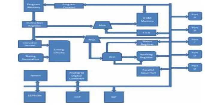
II. BLOCK DIAGRAM
Fig1: Block diagram of speech recognition system
Logistics:
Hardware components: PIC MCU, Speech Recognition kit, and battery charging unit.
Software tools: Development tool – MPLAB v7.42,
Hardware Compiler - HI-Tech PIC C, Programmer - PIC Flash,
Hardware Simulation tool - Proteus v7.6Sp0
III. HARDWARE CIRCUIT DESIGN:
POWER SUPPLY:
A power supply is an electronic device that supplies electric energy to an electrical load. The primary function of a power supply is to convert one form of electrical energy to another. As a result, power supplies are sometimes
referred to as electric power converters. Some power supplies are discrete, stand-alone devices, whereas others are
built into larger devices along with their loads. Examples of the latter include power supplies found in desktop
Specifications:
The suitability of a particular power supply for an application is determined by various attributes of the power
supply, which are typically listed in the power supply's specification. Commonly specified attributes for a power
supply include:
Input voltage type (AC or DC) and range
Efficiency of power conversion
The amount of voltage and current it can supply to its load
How stable its output voltage or current is under varying line and load conditions
How long it can supply energy without refueling or recharging (applies to power supplies that employ
portable energy sources)
Operating and storage temperature ranges
PIC MICROCONTROLLER:
PIC is a Peripheral Interface Microcontroller which was developed in the year 1993 by the General Instruments
Microcontrollers. It is controlled by software and programmed in such a way that it performs different tasks and
controls a generation line. PIC microcontrollers are used in different new applications such as smart phones, audio
accessories and advanced medical devices. There are many PICs available in the market ranging from PIC16F84 to
PIC16C84. These types of PICs are affordable flash PICs. Microchip has recently introduced flash chips with
different types, such as 16F628, 16F877 and 18F452. The 16F877 costs twice the price of the old 16F84, but it is
eight times more than the code size, with more RAM and much more I/O pins, a UART, A/D converter and a lot
more features.
PIC Microcontrollers Architecture
The PIC microcontroller is based on RISC architecture. Its memory architecture follows the Harvard pattern of
separate memories for program and data, with separate buses.
1. Memory Structure
The PIC architecture consists of two memories: Program memory and the Data memory.
Program Memory: This is a 4K*14 memory space. It is used to store 13-bit instructions, or the program code. The program memory data is accessed by the program counter register that holds the address of the program memory.
The address 0000H is used as reset memory space and 0004H is used as interrupt memory space.
Data Memory: The data memory consists of the 368 bytes of RAM and 256 bytes of EEPROM. The 368 bytes of RAM consists of multiple banks. Each bank consists of general purpose registers and special function registers.
The special function registers consist of control registers to control different operations of the chip resources like
Timers, Analog to Digital Converters, Serial ports, I/O ports, etc. For example, the TRISA register whose bits can be
changed to alter the input or output operations of the port A.
The general-purpose registers consist of registers that are used to store temporary data and processing results of the
data. These general-purpose registers are each 8-bit registers.
Working Register: It consists of a memory space that stores the operands for each instruction. It also stores the results of each execution.
Status Register: The bits of the status register denote the status of the ALU (arithmetic logic unit) after every execution of the instruction. It is also used to select any one of the 4 banks of the RAM.
File Selection Register: It acts as a pointer to any other general-purpose register. It consists of a register file address, and it is used in indirect addressing.
Another general-purpose register is the program-counter register, which is a 13-bit register. The 5 upper bits are
used as PCLATH (Program Counter Latch) to independently function as any other register, and the lower 8-bits are
used as the program counter bits. The program counter acts as a pointer to the instructions stored in the program
memory.
EEPROM: It consists of 256 bytes of memory space. It is a permanent memory like ROM, but its contents can be erased and changed during the operation of the microcontroller. The contents into EEPROM can be read from or
written to, using special function registers like EECON1, EECON2, EEDATA, etc.
2. I/O Ports
PIC16 series consists of five ports, such as Port A, Port B, Port C, Port D and Port E.
Port A: It is a 16-bit port, which can be used as input or output port based on the status of the TRISA register.
Port B: It is an 8-bit port, which can be used as both input and output port. 4 of its bits when used as input can be changed upon interrupt signals.
Port C: It is an 8-bit port whose operation (input or output) is determined by the status of the TRISC register.
Port D: It is an 8-bit port, which apart from being an I/O port, acts as a slave port for connection to the microprocessor bus.
3. Timers
PIC microcontrollers consist of 3 timers, out of which the Timer 0 and Timer 2 are 8-bit timers and the Time-1 is a
16-bit timer, which can also be used as a counter.
MICROPHONE:
A microphone is a device that captures audio by converting sound waves into an electrical signal. This signal can be
amplified as an analog signal or may be converted to a digital signal, which can be processed by a computer or other
digital audio device.
While all microphones (or "mics") serve the same basic function, they can capture audio in several different ways.
NOTE: Microphones perform the opposite action of speakers, which convert electrical signals into sound waves.
TECHNOLOGY:
SPEECH RECOGNITION:
Speech recognition is classified into two categories, speaker dependent and speaker independent.
Speaker dependent systems are trained by the individual who will be using the system.
Speaker independent is a system trained to respond to a word regardless of who speaks.
Speech recognition systems have another constraint concerning the style of speech they can recognize. They are
three styles of speech: isolated, connected and continuous.
Isolated speech recognition systems can just handle words that are spoken separately. This is the most common speech recognition systems available today.
Connected is a half way point between isolated word and continuous speech recognition. Allows users to speak multiple words. The HM2007 can be set up to identify words or phrases 1.92 seconds in length.
Speech Recognition Sensors:
Ultrasonic Sensors:
The ultrasonic processing is similar to radar. The ultra high frequency acoustic tone is thrown at a moving object,
the reflections produced are recorded by a receiver. The Doppler effect governs the frequency of the tone reflected,
the equation for it can be expressed as:
f = f0(1+ v c),
f0= emitted tone frequency
f= reflected tone frequency
v= velocity of reflecting surface towards the emitter
c= speed of sound
Thus we can conclude that if the reflecting surface is moving far from the emitter, the recorded frequency tone will
be lower and vice versa. The reflected signal will consist of a sum of sinusoids having different strengths and
frequencies. In a case where a person is talking, the articulator motion during speech production will cause the
Physiological Sensor:
It is a device developed at Army Research Laboratory. This sensor physically couples to a patient and records the
medical information such as the patient’s heartbeat and respiration. This sensor is worn around the throat.
It is useful in places where there is too much noise. The words spoken by a person in a microphone is compared with
the data obtained from the physiological sensor attached on the neck of the person and then the words or the
sentences are determined easily.
Earlier it was difficult to recognize speech using this sensor in IBM’s Via voce because of the distortions caused in
speech. But later on, Rockwell Science Center a Hidden Markov model based speech recognizer to be used with the
physiological sensor.
These two were the common sensors which have been developed. Research and development on other types of voice
recognition sensors is already being carried out nowadays.
VOICE RECOGNITION SYSTEM:
The voice recognition system is the device’s capacity to understand spoken instructions. It is actually a type
of embedded system. When used with a computer an ADC is used which converts varying analog voice signals into
digital pulses or digital signals, to be easily understood by the computer. The hard drive already has the forms of
speech stored in it. The voice signal is decoded and checked against the stored forms. Sometimes due to the presence
of other voices and noises, the output does not come out to be accurate.
Classification Of Voice Recognition System:
There are four types of voice recognition systems.
1. Isolated Voice Recognition System: This system requires a brief pass between the words spoken.
2. Continuous Voice Recognition System: as the name suggests, this system does not require any pass between
the words.
3. Speaker Dependant Voice Recognition System: This system identifies the speech from a single speaker only.
That means only a certain speaker can get passed through this system.
4. Speaker Independent Voice Recognition System: This system can identify speech of any person.
H-BRIDGE:
H-bridge Sometimes called a "full bridge" the H-bridge is so named because it has four switching elements at the
"corners" of the H and the motor forms the cross bar.
The key fact to note is that there are, in theory, four switching elements within the bridge. These four elements are
often called, high side left, high side right, low side right, and low side left (when traversing in clockwise order).
Fig 4: H-Bridge
DC MOTOR:
Fig 5: Dc Geared Motor
DC motors are configured in many types and sizes,
including brush less, servo, and gear motor types. A
motor consists of a rotor and a permanent magnetic
field stator. The magnetic field is maintained using
either permanent magnets or electromagnetic
windings.
IV. OPERATION AND WORKING VOICE RECOGNITION SECURITY SYSTEM:
In order to convert the speech or spoken words into a computer command, several complex steps are performed by
the computer. The analog to digital converter converts the voice signal into digital signal for the computer.
The ADC digitizes the sound wave at frequent intervals by taking some precise measurements. This sampled or
digitized sound is then filtered in order to remove noise. This is also done to separate the sound in different bands of
frequency. Sound also gets normalized by it. Different people have different speed of speaking, so the sound is
The next step is to divide the signal in smaller segments as few hundredths or thousandths of a second. These signals
are then matched with the known phonemes. The smallest element of any language is said to be a phoneme. In the
English language, there are approximately 40 phonemes. Different languages have different number of phonemes.
Next is the most difficult step in speech recognition. The phonemes are examined in the context of other phonemes
which are around them. A complex statistical model then examines the contextual phoneme plot and it is compared
with a large library of words, sentences and phrases. Then the program finally determines the words being said by
the user and displays the output as text or issues a command. The earlier speech recognition systems applied a set of
syntactical and grammatical rules that if the spoken words follow these rules then the words can be determined. But
the human language cannot be modeled by just a set of rules.
Voice recognition system models
The hardware design of a very basic voice recognition security system involves three main elements:
1. A microphone circuit.
3. LCD Display.
The microphone circuit is connected to the ADC of the controller. A set of words and phrases is stored in the
memory of the microcontroller. Once a word is spoken in the mic, the adc converts it into digital signals which pass
through digital filters and finally LCD, connected to the microcontroller displays the words spoken.
Fig6: microcontroller with microphone
This car is designed to be operated through the
interfacing of a human and a machine. The robotic
vehicle performs its operations based on the voice
commands given by a human. This operation is
achieved by using an PIC controller with a voice
recognition module such as HM2007 etc. Voice
commands or the push buttons control the direction
of the robotic car. From transmitter to receiver end,
the voice signals or commands are sent by the RF.
The car can move left, right, forward or backward depending upon the command given to it. There are two motors
interfaced with the PIC microcontroller. These two motors control the movement of the robotic car. The commands
are converted by the RF transmitter and encoded into digital data. The receiver circuit in the vehicle receives the
data and decodes it to send it to another microcontroller which can drive the DC motors. A motor driver IC is used
to control the directions and movements of the car according to the decoded data of voice commands.
V. CONCLUSION
This voice controlled vehicle can also be operated with the help of a DTMF technology for a very long-range
communication. Through DTMF, the car can be controlled through a mobile phone.
Voice recognition system involves a biometric technology. This technology is getting very popular nowadays for
security purposes and for electronics projects among engineering students. The individuals are easily identified
through it and the chances of theft and fraud are reduced. Other methods of biometric identification are iris/eye scan,
fingerprints, face scan, hand print, voice print, handwriting etc. Through the biometric voice recognition system, the
unique voice characteristics of an individual can be recognized. This security system has a wide range of
applications and uses as for ATM manufacturers, automobile manufacturers and in cell phone security access system
to eliminate any sort of theft or fraud. It is also have many applications in embedded based applications.
REFERENCES
[1]: “Design with PIC microcontrollers” by J. B. Peatman
[3]: “Microcontrollers: Architecture Implementation and Programming” by Hintz
[4]: “Embedded System Design Based on 8051 and PIC Family Microcontroller” by T. Bezboruah, A. Goswami, K.
C. Sarma