48 | P a g e
AUTOMATIC PHASE SELECTOR
Chaitalee P. Bhise
1, Ananta A. Nare
2, Nilesh M. Wankhade
3 1,2,3,Lecturer, Department of Electrical & Power Engineering,
STC, SPRT, Khamgaon, Maharashtra, (India)
ABSTRACT
In many cases we have three phase supply where only single phase is used to run the equipment such as load of
Operation Theater in hospitals, commercial Internet servers. In some cases if phase supply voltage is low in
any of the load driving phase and if you wish to run all the equipment in proper way as required then you must
be sure about the continues and normal single phase electrical supply. By the use of proper TPDT relay logic
we can instantly select proper available phase and avoid the short circuit condition between the different
phases. However fuse of proper rating should be used in three phase’s i.e. inputs lines. At that time correct
voltage must be available for driving the load. in the building, to run all the equipment on the single phase we
have to shift low voltage phase to the correct available phase voltage by using electrical component such as
transformer, under voltage, overvoltage protection and TPDT relay.
Keywords
— under Voltage, overvoltage, relay.
I. INTRODUCTION
49 | P a g e
II. LITERATURE SURVEY
2.1 Automation Requirement:
This topic is covered from journal of research and development and ameliorating power supply problem in Nigeria authored by A.A and Yusuf from that book automation is required in Nigeria because there is an electric supply and these also provide journal R&D department hence there is necessity for automation. These also covered from international journal of engineering and technology. The next system was proposed by Mariuz Malinowski named as “Simple Direct Power Control Of Three Phase PWM Rectifier Using Space Vector Modulation(DPC-SVM) in April 2004 but due to variable switching frequency and violation in polarity there was a need to design such a system which would overcome all of above system drawback.
2.2 Electronic Components
:
This topic is covered from power electronics authored by M.D.Singh and K. B. Kahnchandani from that text book covered the function and use of CAPACITORS, RESISTORS, TRANSISTERS, VOLTAGE REGULATOR IC-7812, LED etc. these also covered from principle of Electronics.Newdelhi.India:S.Chand and Company-Ltdmoh.Ajmal P.
2.3 Electrical Components:
The information for electrical component used in this topic is taken from V. K. Mehta, B.L.Thereja and Use of Transformer, Relay, Fuse Etc These Also Covered Fromshepherdj. Mortan
III. METHODOLOGY
3.1 BASIC IDEA:
In this topic the load is shifted on different phase according to phase selector which select the phase according to availability of phase and avoid the short circuiting of three phase available by using transformer , rectifier , voltage regulator IC-7812 ,Operational Amplifier LM-324, Zener Diode , Resistors And Relay. Hence for convenience indicating lights are provided which indicate which phase is running in load
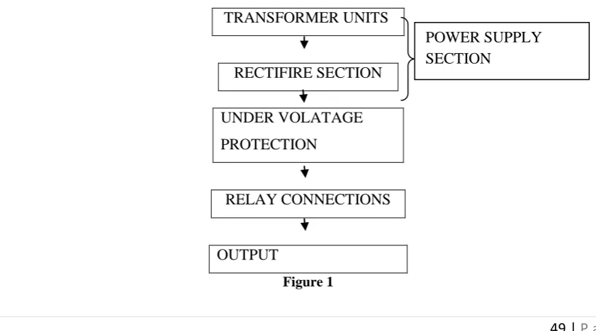
3.2 STAGE OF IMPLIMENTATION:
The automatic phase changer design was implemented in three units are as given below
TRANSFORMER UNITS
RECTIFIRE SECTION
UNDER VOLATAGE
PROTECTION
RELAY CONNECTIONS
OUTPUT
Figure 1
50 | P a g e
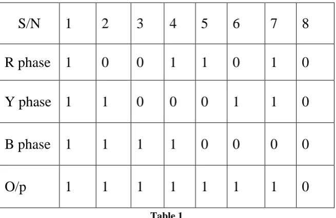
3.3 Design Development and ConsiderationsDuring the design of the phase selector, we have provided a lot of over voltage and under voltage protection for those considerations, conditions and cases where considered which gives the accurate and healthy phase for the load. It is shown by following Truth table.
S/N
1
2
3
4
5
6
7
8
R phase 1
0
0
1
1
0
1
0
Y phase 1
1
0
0
0
1
1
0
B phase 1
1
1
1
0
0
0
0
O/p
1
1
1
1
1
1
1
0
Table 1
In these conditions in mind and also knowing the fact That the coming up and going off of power supply from power providers) does not notify anyone before making their decision in this part of the world. As such the conditions and questions considered are as follows; The power supply of 240 volts single phase for theThree phases at a frequency of 50 HZ was assumed.
1. If load of 5 kW was assumed.
2. When the whole three phase supply is present then from above table the output is 1 i.e. Healthy phase. 3. When two out of the three phase are present then from above table the output is 1 i.e. Healthy phase. 4. The relay logic is made such that more than one phase comes in contact with each other
The above conditions and output of that condition were considered during the design of the phase selector control. Having from the given truth table, the “X” is the output of all the conditions which is occur in system which is given in a particular row of table, i.e. “1”meaning on, while “0” means off, or no output from the phase selector.
IV. PROBLEM STATEMENT
4.1 SELECTION
51 | P a g e
4.2 BLOCK DIAGRAM
In this topic the load is shifted on different phase according to phase selector which select thee phase according to availability of phase and avoid the short circuiting of 3 phase available. By using transformer, rectifier, voltage regulator IC-7812, operational amplifier LM-324, zener diode, resistor and relay.
Figure 2
V. WORKING
This circuit protects appliances from over and under voltage operational amplifier IC-LM324 IS used as a comparator. IC LM-324 consists of 4 operational amplifiers from which only two amplifier are use in the circuit. The un regulated power supply is connected to the series combination of resister R1 and R2 and pot meter VR1.The same supply is connected to 6.82v zener diode through resistor R3.
52 | P a g e
5.1 OVERALL CIRCUIT
Figure 3
In automatic phase selector load is shifted on different phase according to availability of phase
Now consider the normal condition all the three phase running normally. At that situation the voltage sensing unit that is operational amplifier sense the voltage and trigger to the relay and the relay will drive to main relay. When all the phase are available the load will be driven by R-phase.
The arrangement of main relay is made in such a way that in case of availability of all the phase under normal conditions only r-phase will drive the load. But when the R-phase goes below under voltage level then the load is shifted on Y-phase.
When both the phase R & Y are unavailable at that time the load will be shifted on b-phase but as soon as any one phase from R &Y is come in normal condition then the load will is shifted on that respective phase.
In that system we have the relay logic in which the priority given to R-phases and then Y-phase and lastly to B-phase. Like that we get continuous power supply to the load from available B-phase.
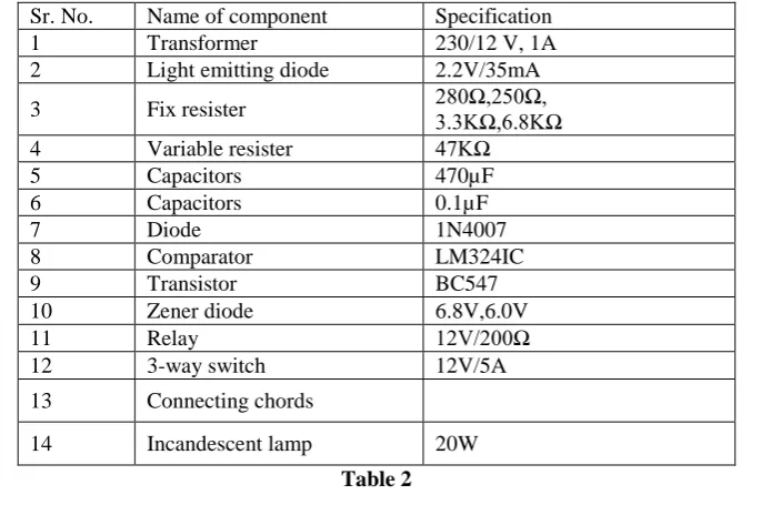
The list of components and there specifications are given below.
Sr. No. Name of component Specification 1 Transformer 230/12 V, 1A 2 Light emitting diode 2.2V/35mA 3 Fix resister 280Ω,250Ω, 3.3KΩ,6.8KΩ 4 Variable resister 47KΩ 5 Capacitors 470µF 6 Capacitors 0.1µF 7 Diode 1N4007 8 Comparator LM324IC 9 Transistor BC547 10 Zener diode 6.8V,6.0V 11 Relay 12V/200Ω 12 3-way switch 12V/5A 13 Connecting chords
14 Incandescent lamp 20W
53 | P a g e
5.2 OUTPUT:We arrange the transformer in such a way that it gives rectified output to obtained signals the signal gives input to phase shifter and controller these signal is given to three relay. According to signal relay operates and gives output which is given to selected relay.
Condition 1
When phase R & B present or only R-phase present then the under voltage protection relay for R-phase trip.
Condition 2
When R-phase is unavailable and phase Y & B phase is available then load is shifted on phase Y in that condition when r comes in normal situation then load will be shifted on R-phase then the under voltage protection relay for Y-phase trip.
Condition 3
When both R & Y is unavailable then load is shifted on B-phase-in that case if B-phase drive the load and R & Y phase comes in normal condition then load is shifted according to priority. Then the under voltage protection relay for B-phase trip The input output voltage across each transformer is found as below.
Vin(volt)
V out (volt)
R-phase Y- phase B- phase
230 12.36 12.40 12.12 220 11.83 11.58 11.77 210 11.32 11.33 11.20 200 10.73 10.60 10.46 190 10.20 10.20 10.30 180 9.70 9.31 9.62
Table 3
VI. CONCLUSION
Hence it concludes that by such a arrangement of electrical and electronics component we got continuous single phase supply from any available phase out of three phase. Also studied the operation of operational amplifier and whole under voltage protection kit and also studied the operation of three way relay.
In this work the automatic phase changer using LM324 comparator has been design, built and tested. The system operates smoothly as expected. It is reliable, durable and portable. The cost involved in developing it , make it much more affordable than comparator product. We the use of automatic phase changer we protect home appliances from voltage unbalancing. It is used in following locations such as Hospitals, Laboratories, Administrative buildings, Home appliances, Libraries
VII. FUTURE SCOPE
54 | P a g e
REFERENCES
[1] Steven M. Hietpas, Mark Naden,”Automatic Voltage regulator using an AC Voltage-Voltage Converter,” IEEE Transaction on Industrial Application, Vol 36,no 1, January-February 2000.
[2] Gua-Kiang Hung, Chih- chang Chang, “Automatic Phase Shift Method for Islanding Detection of Grid – Connected Photovoltaic Inverters,” IEEE Transaction On Energy conversion, Vol.18.No.1, March 2003. [3] Erika Twining, “Grid Current Regulation Of A Three Phase Voltage Source Inverter With an LCL Input
Filter,” Transaction On Power Electronic, Vol .18, No .3 May 2003. Mariusz Malinowski and Jasinski [4] Marek,”Simple Direct Power Control Of Three Phase PWM Rectifier Using Space Vector Modulation