2133 | P a g e
IMAGE COMPRESSION TECHNIQUE USING
GRADIENT BASED EDGE DETECTION AND
F-TRANSFORM
A. Taneja
1, N. Neeru
2PG Student, Dept. of CSE, Punjabi University, Patiala
1Assistant Professor, Dept. of CSE, Punjabi University, Patiala
2ABSTRACT
In this work, inclination based edge recognition has been proposed, which gives better edges expected to compression
and decompression as it accounts the nearby neighborhood of a pixel in a 3*3 window. Technique utilizes corner
pixels of the 3*3 window and discovers most extreme slope area which is additionally contrasted and a limit. On the
off chance that it is more than a limit than the inside pixel will be found as edge pixel in the image. At that point three
classes has been assessed called low force (LI), a medium power (MI) or a high force (HI) in non-covering pieces of
8*8 size and compression sort is picked by that esteem. After that Huffman coding is connected to accomplish more
compression. Same switch steps occurred for recreation of the image in which Huffman deciphering is actualized first
and after that reverse F-change is connected to get the decompressed image. Examination comes about demonstrates
that decompressed images have high PSNR and SSIM records and can be appropriate for compression decompression
purposes
Keywords:
Compression, decompression, edge detection,F-transform
I. INTRODUCTION
Aimage can be characterized as a network of pixel or power esteems. Imagecompression is utilized to diminish the
excess and arbitrariness introduce in the image on the grounds that to expand the putting away limit and proficiency
level of the images. In this way it is basic to pack the images by putting away just the required data expected to
reproduce the image. To pack any image, repetition must be evacuated. Now and then images having extensive
regions of same shading will have vast redundancies and correspondingly images that have regular and expansive
changes in shading will be less repetitive and harder to compress[1], [2], [3].
The fundamental goal of this paper is to lessen superfluity and excess of the JPEG and PNG image information
keeping in mind the end goal to have the capacity to store or transmit information in a proficient frame utilizing DCT
and DWT. We have endeavored to ponder the diverse imagecompression calculation and assess their execution on
various image positions and furthermore built up a framework for imagecompression utilizing Discrete Wavelet
Transform and contrast the outcomes and the current procedures or frameworks. Imagecompression should be
possible in two ways:
2134 | P a g e
In the event that any pixel esteem is transformed from an advanced image and after that vitality will be lost and thissystem is called "lossy" compression. The measure of data held by aimage after compression and decompression is
known as "lossless" compression [4].
II. LITERATURE SURVEY
AfshanMullaet. al. [5] offers three novel systems viz. Vitality Detection Algorithm, Cognitive Band Determination
and CSR-DWT strategy for packing shading RGB images.
SafaVakiliet. al. [6] proposed a powerful compression plot in which 3D wavelet change and SPIHT are jointed to
fulfill MRI image quality reproductions.
Shuhui Wang et. al. [7] proposed a compound imagecompression technique named United Coding (UC). UC, as its
name demonstrates, joins intraframe half breed coder and a few common lossless coding instruments, for example,
word reference entropy coder, RLE, PNG channels, and Hextile coding.
Rajasekhar V et. al. [8] played out an enhanced and productive Discrete Wavelet Transform calculation. Keeping in
mind the end goal to expand the execution and to diminish the computational complexities adjustments have been
made and the 9/7 channel is utilized.
Amol Baviskar et. al. [9] presents the novel Sub-band Replacement DWT (SR-DWT) based compression strategy for
ongoing image preparing. The system for imagecompression and recovery is explained alongside the scientific model
of the calculation is introduced. T. A. T. A. Laskaret. al. [10] proposed a calculation on Image Compression utilizing
DWT and Inverse DWT. The most recognizing highlight of utilizing DWT and Inverse DWT is that it won't just
empower to pack aimage yet in addition will keep up the nature of the image as it was in its unique shape, which was
not really conceivable before in other imagecompression strategies.
III PRESENT WORK
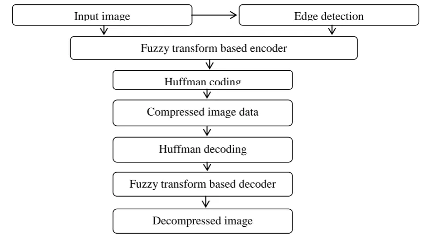
The system module has been described as below.
Figure 1: block diagram for the proposed algorithm.
Input image
Fuzzy transform based encoder
Huffman coding
Edge detection
Decompressed image
Fuzzy transform based decoder
2135 | P a g e
Steps in the algorithm
The proposed image compression method follows three steps:
1. Edge detection using gradient of center pixel with respect to 3*3 neighbor pixels
In this step, each input image block is classified into either a low intensity (LI), a medium intensity (MI) or a high
intensity (HI) block using gradient based detection algorithm. The algorithm starts by dividing the image into
overlapping blocks that would be individually evaluated for inclusion of edges.
Figure 2: (a) 3 × 3 block edges and (b) Selected pixels for embedding 3 × 3 block.
At first, input image has been divided into overlapping blocks of the size n × n .Then vertical ,horizontal, first
diagonal and second diagonal edges has been used in which absolute mean differences has been evaluated and a
maximum of all has been chosen. Then it is compared with a threshold value. If it comes greater than corresponding
center pixel will be chosen as edge pixel.
2. F-change
The squares characterized into LI, MI and HI pieces are packed utilizing the F-change calculation. Monotonicity of a
capacity is an imperative property safeguarded by F-change that aides in enhancing the nature of compacted
(recreated) image [11]. Information image is first separated into squares of size n × n. In light of the edge image got
from inclination edge recognition calculation, the information image pieces are arranged into LI squares, MI squares
and HI pieces. These pieces are additionally packed utilizing F-change into various size squares. Since LI squares
contain less data (as it contains less edge pixels) thus can be packed more when contrasted with HI pieces.
3. Huffman coding and disentangling
The force based F-change packed image information is additionally encoded utilizing Huffman coding system to
accomplish low piece rate [12]. The compacted image is additionally encoded utilizing Huffman coding plan to
accomplish more compression. Huffman code is a prominent strategy utilized for lossless information compression
presented by Huffman [4], is ideal in sense that this technique for encoding brings about briefest normal length. This
2136 | P a g e
important data introduce in aimage. The compacted hinders by F-change are additionally encoded utilizing losslessHuffman encoding to accomplish bring down piece rate.
IV. RESULTS
This area contains the screenshots of the plan and execution of the proposed framework and the test aftereffects of the
exactness of the proposed framework. The examination of the precision of the past framework and the proposed
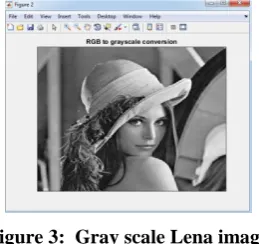
framework is finished.Select the cover image needed for compression. In this step, the image to be compressed is selected.
Figure 3: Gray scale Lena image
The reconstructed images by both methods existed and proposed has been given below
Figure 4: Decompressed image using canny edge detection method
Figure 5: Decompressed image using gradient edge detection method
V. PERFORMANCE EVALUATION
Mean Square Error (MSE): The MSE signifies the cumulative squared error between the input and the output
image. To compute the PSNR, we first calculate the mean squared error. It is calculated by the following equation
(1).
2
,
[ 1(m, n)
2(m, n)]
*
M N
l
l
MSE
M
N
2137 | P a g e
Where N and M are the number of columns and rows in the input images, respectively and I1 (m, n) is the inputimage, I2 (m, n) is the decompressed image.
Peak Signal-to-Noise Ratio (PSNR): Signal–to-noise ratio (SNR) is a mathematical measure of image quality. It
is based on the pixel difference between two images. The SNR measure is an estimate of quality of reconstructed
image compared with original image. PSNR is defined by the following equation (2)
2
10
10 log
R
PSNR
MSE
(2)The PSNR takes the signal strength into consideration. The values were used to evaluate the quality of the image.
Where R represents maximum fluctuation or value in the image, its value is 255 for 8 bit unsigned number. Similarly
other parameters i.e. SAD,SSIM,RMSE has been evaluated.
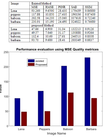
Table 1: Performance evaluation using different Quality Indices
2138 | P a g e
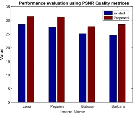
Figure 7: Performance evaluation using PSNR Quality metrics
It has been concluded that proposed method using gradient based edge detection gives better results when compared
with canny edge based edge detection method.
V. CONCLUSION
There are numerous techniques proposed in recurrence space by utilizing change strategies i.e. DCT, DWT and so on
however they actualized on entire image as similarly and does not consider the substance varieties in the image. To
consider variable rate of compression in same image, edge identification situated strategy has been proposed in which
edge pixels are discovered utilizing angle of the area and after that diverse compression rates has been chosen for the
non-covering pieces of the image to be compacted. Where there are more edges in the piece, calculation choses less
compression and where less no. of edges is, calculation chooses high compression rate. F-change has been utilized for
compression and decompression purposes. Analyses comes about shows high an incentive in PSNR, SSIM quality
measurements after decompression the images and less estimations of MSE, RMSE and SAD parameters as this is a
prerequisite of a decent compression decompression procedure
REFERENCES:
[1] M.M. Chowdhury and A.Khatun,”Image Compression using Discrete Wavelet Transform”, Published in:
International Journal of Computer Science Issues, Vol. 9,Issue 4, No.1, July, 2012, pp. 327-330.
[2] Y.Sukanyaand J.Preeti,”Analysis of image compression Algorithm using Wavelet Transform with GUI in
Matlab”, Published in: IJERT, eISSN:2319-1163,pISSN:2321-7308, Vol. 2, Issue:10, oct, 2013.
[3] A.Averbuch,D.Lazerand M.Israeli, ”Image Compression using Wavelet Transform and Multi resolution
decomposition”,Pubished in: IEEE Transactions on Image Processing,Vol.5,No.1,January,1996.
[4] B.Nilesh,S.Sachin,N.Pradip, and D.B.Rane, ”Image Compression using DWT” Published in: ISSN: 2249-3433,
IJCTEE,Volume3,Special Issue,March-April 2013.
[5] A. Mulla, A. Baviskar, J. Baviskar and M. Gulati, "Cognitive Sub-Band Replacement DWT based image
compression scheme," 2015 Advances in Wireless and Optical Communications (RTUWO), Riga, 2015, pp. 86-93.
[6] S. Vakili and M. Khalili, "A joint 3D DWT and SPIHT based algorithm for 3D MRI image compression," 2015
2139 | P a g e
[7] Shuhui Wang & Tao Lin, "United coding method for compound image compression" Published in: MultimediaTools and Applications August 2014, Volume 71, Issue 3, pp 1263–1282
[8] V. Rajasekhar, V. Vaishnavi, J. Koushik and M. Thamarai, "An efficient image compression technique using
discrete wavelet transform (DWT)," 2014 International Conference on Electronics and Communication Systems
(ICECS), Coimbatore, 2014, pp. 1-4.
[9] A. Baviskar, S. Ashtekar, A. Chintawar, J. Baviskar and A. Mulla, "Performance analysis of sub-band
replacement DWT based image compression technique," 2014 Annual IEEE India Conference (INDICON), Pune,
2014, pp. 1-6
[10] A. H. M. J. I. Barbhuiya, T. A. Laskar and K. Hemachandran, "An Approach for Color Image Compression of
JPEG and PNG Images Using DCT and DWT," 2014 International Conference on Computational Intelligence
and Communication Networks, Bhopal, 2014, pp. 129-133.
[11] D.A Huffman et al.,” A method for the construction of minimum redundancy codes” published in Proceedings of
I.R.E (1952), pp. 1099–1101
[12] Deepak Gambhir ;NavinRajpal,” Edge and Fuzzy Transform Based Image Compression Algorithm: edgeFuzzy.”
Published in Artificial Intelligence and Computer Vision Volume 672 of the series Studies in Computational