Polarized Solid State Target
HartmutDutz1,,StefanGoertz1,, andWernerMeyer2,
1Physikalisches Institut, Universität Bonn, Nussallee 12, 53115 Bonn
2Institut für Experimentalphysik - AG I, Ruhr-Universität Bochum, Universitätsstraße 150, 44780 Bochum
Abstract.The polarized solid state target is an indispensable experimental tool to study single and double po-larization observables at low intensity particle beams like tagged photons. It was one of the major components of the Crystal-Barrel experiment at ELSA. Besides the operation of the ’CB frozen spin target’ within the exper-imental program of the Crystal-Barrel collaboration both collaborative groups of the D1 project, the polarized target group of the Ruhr Universität Bochum and the Bonn polarized target group, have made significant de-velopments in the field of polarized targets within the CRC16. The Bonn polarized target group has focused its work on the development of technically challenging polarized solid target systems towards the so called ’4π continuous mode polarized target’ to operate them in combination with 4π-particle detection systems. In par-allel, the Bochum group has developed various highly polarized deuterated target materials and high precision NMR-systems, in the meantime used for polarization experiments at CERN, JLAB and MAMI, too.
1 Introduction
Within the recent decades polarized solid targets as well as polarized particle beams evolved into indispensable tools in order to explore the spin structure of the proton and the neutron. Single and double polarization measurements were performed with a variety of different particles beams, among them not only experiments with polarized electrons and real photons. Protons, antiprotons and even polarized muons have been used so far at various laboratories [1]. (Double) polarization experiments at ELSA [2, 3] with tagged photon beam fluxes in the order of some mega-hertz have to rely on polarized solid targets with high tar-get densities in order to provide sufficient luminosities of the particle reactions of interest. The developments of the polarized targets for particle physics experiments at ESLA within the CRC16 were twofold. On the one side we fo-cussed on the enhancement of the figure of merit (FOM), which is defined as the product of the numberntof target particles per cm3, the squared target polarization P2
t and the squared ratio f2of the number of polarizable nucleons and the total number of nucleons in the target. Improve-ments in Pt and f are directly related to the search and preparation of suitable target materials and need a detailed understanding of the dynamic nuclear polarization (DNP), as given by the spin temperature theory (for an overview we refer to [1] and for deeper studies see [4]).
On the other hand we worked on a significant enhancement of the luminosityLand angular acceptanceΔΩof the po-larized target beyond the standard ’frozen spin technique’
e-mail: [email protected] e-mail: [email protected] e-mail: [email protected]
towards the so called ’large angular continuous mode tar-get’ or ’4πcontinuous mode polarized target’. The goal is to enhance the reaction counting rate N, which is defined asN=L·dσ/dΩ·ΔΩ, and thus to improve considerably upcoming polarization experiments. The new scheme led to challenging and outstanding developments in cryogen-ics and superconducting magnet technology in the field of polarized solid state targets.
Besides the developments of new polarized target compo-nents and materials we operated the existing ’CB frozen spin target’ (former ’GDH frozen spin target’) as a major component of the Crystal Barrel experiment at ELSA for (double) polarization experiments.
Over the period of the CRC the goals and methods of the Bochum polarized target group focused on intense re-search on polarized target materials and their polarization behavior and the design and construction of more accurate as well as sensitive polarization measurement equipment. The broad spectrum of research covered the following top-ics:
• construction of a ’top-loading’4He refrigerator for target material research
• pulsed and CW NMR for polarization measurements [5, 6]
• polyethylene and other oxygen-free hydrocarbons (alkanes) as polarized target materials
•conventional X-band and high field elctron paramag-netic resonance (EPR) measurements for systematic target material studies
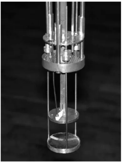
Apart from the performance of the refrigerator and from the strength of the magnetic field, the achievable max-imum polarization in a certain target material strongly depends on the efficiency of the DNP process. This efficiency is intimately related to the properties of the paramagnetic centers, from which the polarization is transferred to the nuclei. In particular the longitudinal Zeeman and the dipolar relaxation times as well as the strength of the electronic non-Zeeman interaction deter-mine the minimum spin temperature and thus the max-imum polarization of the nuclear spins. Therefore, to optimize the performance of a given target material, it is essential to characterize the paramagnetic system gen-erated by the various doping methods as completely as possible. Meanwhile, besides a conventional X-band (10 GHz) EPR spectrometer, which has been used since several years and which has produced a lot of very use-ful results (e.g. radical characterization and structure studies [7] or observation of spin temperature in 6LiD [8]), also a V-band (70 GHz) spectrometer is in use in the Bochum polarized target laboratory [9]. This self-built device is implemented in the4He polarization appara-tus and enables EPR measurements in the DNP regime at 2.5 T and down to 1 K. Especially for deuterated target materials very important results concerning the correlation between the properties of the paramagnetic species (i.e. EPR linewidth) and the maximum achiev-able deuteron polarization have been obtained at DNP relevant magnetic fields (see Fig. 1).
•Magnetic field dependence of the polarization in ni-troxyl and trityl doped deuterated alcohol materials With respect to the projected ’4π-continuous mode’ po-larized solid state target, it is of great importance to ob-tain an extensive knowledge about the polarization havior within the moderate magnetic field region be-tween 1.8 T and 2.5 T. Since with internal polarizing field values beyond 2.5 T will probably not be accessi-ble in the near future experiments with such targets will have to rely on a thorough optimization of the polar-ization conditions in order to achieve polarpolar-ization val-ues as high as required. Such an optimization means to check material parameters like radical concentration, EPR line-width and electron as well as nuclear relax-ation times in dependence of the magnetic field with the goal to pin down an optimal set of parameters for each material. On the other hand the results of such mea-surements will help to specify the requirements for the construction of an internal polarizing magnet in terms of magnetic field values and magnetic field homogeneity. A new top-loading4He-refrigerator capable to be oper-ated up to 7.0 T has been successfully set into operation. Measurements of the electron relaxation time at 2.5 T have been performed in the very homogeneous mag-netic field (ΔB/B < 10−5). For this a new pulsed nu-clear magnetic resonance (NMR)-system has been built, which is able to measure relaxation times in the order of
Figure 1: The Fabry-Perot like multimodal resonator of the high field EPR spectrometer (diameter of mirrors: 31 mm). Because at 2.5 T the wavelength of the mi-crowaves equals the dimensions of the solid target sam-ples, a common Single Mode Cavity cannot be used.
milliseconds [10]. This is the first time that such mea-surements have been performed with samples used for particle physics experiments.
Furthermore a new continuous wave NMR-system was built, with which the degree of polarization of the po-larized target materials can be detected with improved precision in the frequency range between 10 MHz and 300 MHz (corresponding magnetic field strengths be-tween 1.8 T and 7.0 T for protons and deuterons, re-spectively). This development was necessary, as for the existing continuous wave NMR-system (Liverpool box) components are obsolete and other parts not available anymore on the electronic market (see Sec. 7.
A microwave system with a center frequency of 56 GHz has been set up and is ready to work. Polarization values for protons at the corresponding field strength of 2.0 T and 1 K are expected to be in the order of some percent. To optimize the preparation of the samples for the par-ticle physics experiments at temperatures <80 mK the 3He/4He dilution refrigerator in the Bochum laboratory has been modified and successfully operated for target material studies at low temperatures.
•design and construction of a new ’transverse holding-coil’ and an ’internal superconducting po-larizing magnet’
•construction of a new horizontal 3He/4He dilution refrigerator for the ’4π-continuous mode’ polarized solid state target
•set-up of a new irradiation facility for target materi-als at the 20MeV Linac of the Bonn accelerator fa-cility and target material studies of irradiated poly-meric materials.
In the following sections 2 - 7 we will describe this work and recent results in more detail.
2 ’CB frozen spin target’ at Crystal Barrel
2.1 Introduction
The experimental program at the Crystal Barrel detector was focused on the measurement of single and double po-larization observables offpolarized nucleons using the ex-isting GDH frozen spin target [11, 12], which with the start of the CRC16 has been labeled as ’CB frozen spin target’. Here we will briefly report on the setup and the perfor-mance of the ’CB frozen spin target’ at the Crystal Barrel detector for polarization experiments at ELSA in the re-porting period of CRC16.
2.2 Setup and performance
Upon completion of the GDH experiment at Mainz the tar-get was moved back to Bonn and has been prepared for the experimental program at ELSA [13]. The main pumping unit was dismounted for revision and has been reinstalled to have a better access to the roots blowers to reduce the down time in case of a failure. In parallel the control unit was upgraded to guaranty a reliable operation of the sys-tem at ELSA. On top of that, the installation included a reconstruction of the mechanical support structure of the target, the railway system to move the polarizing magnet and the Crystal Barrel detector and the main vacuum sys-tem.
For the first run a butanol target material with low electron spin density (1.4×10¹⁹spins/ml) was prepared to guaranty high relaxation times at moderate maximum proton polar-izations. The relaxation time of the proton polarization during the first measurement at ELSA exceeded 500 h in a longitudinal ’holding field’ of 0.64 T. The nucleon polar-ization had to be refreshed every three days to minimize the beam time loss by the time consuming repolarizing process and movement of the detector components. The chosen frozen-spin cycle of about 72 h and a mean value of the target polarization at the beginning of the frozen spin mode of about 60% amounts to an average polarization of 57% during the data taking. After more than 8 years of successfull operation in the GDH experiment, the target has proven its known reliability. It is an ideal experimen-tal tool to study spin dependent reactions in combination with a movable 4π-detection system.
To increase the reliability as well as the operational avail-ability of the existing GDH frozen spin target, we replaced in the second funding period various hardware compo-nents of the control and vacuum-system of the refrigerator. Namely, the PLC- and HMI-systems were completely re-newed and reprogrammed. Due to super-leaks in the front part of the target inserts, both units have been redesigned and reconstructed. We replaced the existing splitted NMR-coaxial cables in the inserts by only one. This led to a reduced heat load of the mixing chamber by longitudinal heat conduction and enabled us to improve the accuracy of the polarization measurement via the NMR-technique. From 2008 to 2013 we run the frozen spin target for more than 15900 hours under cold operational conditions and could provide 7500 hours of longitudinally polar-ized protons up to a maximum polarization of±83% and deuterons up to±70% for single and double polarization experiments with the Crystal Barrel detector.
2.3 Transverse ’holding coil’
One of the major topics of the CRC TR16 was the mea-surement of the target asymmetry T and the double polar-ization observables F and H off the proton and neutron. These observables require a polarization direction perpen-dicular to the scattering plane of the pion nucleon system. To provide such a transverse polarization in the frozen spin target the existing ’longitudinal holding coil’ had to be re-placed by a new ’transverse holding magnet’. To ensure with the new set-up as long relaxation times as achieved with the ’longitudinal holding magnet’, a field strength of at leastBH=0.5 T is needed. And, as a crucial factor for a new magnet design, the maximum load of the current leads inside the dilution refrigerator is limited toIH=33 A. The symmetry of the refrigerator, the available space in the tar-get area as well as the cylindric form of the bobbin defines the ’transverse holding coil’ as a race-track type supercon-ducting magnet. In this design the magnet consists of two individual dipoles bend to a race-track each placed inside the bobbin. Additionally to the electrical parameters the magnet has to fulfill the requirements of a minimized mass distribution to ensure a good detection probability for the outgoing particles and the outer diameter of the magnet which is limited by the geometry of the refrigerator. Taking these considerations and a superconducting wire with a diameter of 0.2 mm into account, the simulation of the magnet led to a solution for each coil consisting out of 510 windings within 7 layers. The combination of both coils result in a maximum field of the ’holding coil’ ofBH
time (3 days). This gives us the opportunity to change the general settings and orientation of the polarization for a measurement of a new polarization observable. On the other hand the special design of the two dipoles inside of the bobbin leaves additional space for an optional solenoid wound on the outer shell of the bobbin. For the future one has with this double coil magnet the possibility to run a transverse and a longitudinal magnetic field to maintain the nucleon polarization in any possible angle to the scat-tering plane in the outgoing pion-nucleon frame by simply varying the currents in both magnets during the data tak-ing.
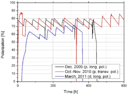
In 2010 the new ’transverse holding coil’ was used in the measurement of the target asymmetry T and the double polarization observable H at the Crystal Barrel detector. In more than 4300 h of cold operation of the frozen spin target it has proven its reliability. At the nominal holding field ofBH =0.5 Tesla, mean relaxation times in the or-der of 370 h have been achieved. The maximum proton polarization was of the order of±83%. In Fig. 2 the polar-ization history for three typical double polarpolar-ization runs in 2009, 2010 and 2011 for longitudinal, transverse, proton and deuteron polarization are shown respectively.
Figure 2: Polarization history plot for three typical double polarization runs in 2009, 2010 and 2011 for longitudinal and transverse, proton and deuteron polarization, respec-tively.
3 A new horizontal
3He/
4He dilution
refrigerator for a 4
π
-continuous-mode
polarized target
3.1 Introduction
Besides the advantage of the good angular acceptance, the frozen spin target has in comparison with a ’continuous mode target’ the disadvantage of a reduced beam time ef-ficiency. It is caused by the polarization refresh cycles and the movement of the polarizing magnet as well as the de-tector components. In best cases a beam time efficiency of
about 80% is attainable.
The second restriction from the ’figure of merit’ point of view is the decay of the polarization during the data taking in all target materials. The overall polarization of an exper-iment using a frozen spin target is given by the relaxation times and limited to approximately 0.8·Pmax. A reduction of the target temperature to increase the relaxation times is suppressed by the Kapitza-resistance in the target material at a given beam intensity. Commonly used intensities up to 107particles/sec are setting the effective target material temperature independently of the lowest refrigerator tem-peratures (e.g. 20 mK) to about 50 mK to 60 mK. Beam intensities above 108 particles/sec are unattainable in the ’frozen spin mode’ operation.
To circumvent the disadvantages of the frozen spin tech-nique we have combined the advantages with those of the ’continuous mode’ operating target to a so called ’4π con-tinuous mode’ polarized target [14]. It is simply a ’frozen spin target’ equipped with an internal superconducting po-larizing magnet for permanent DNP. This new polarized target scheme, which can be described as a continuous mode operating target with a large angular acceptance, leads to an improvement in the figure of merit by a fac-tor of 2 compared to the existing ’CB frozen spin target’. The special features of the target are
• large angular acceptance∼4π(homogeneous mass dis-tribution)
• high average polarization during the data taking (contin-uous DNP at high polarizing field)
• high luminositiesLup to 1033cm−2sec−1
• good beam time efficiency (no maintenance work for the moving of components nor repolarization),
• no moving system for the polarization process required (no detector size restriction, fixed target-detector setup) Once the system will have been installed in the Crystal Barrel detector it will provide highly polarized nucleons with good access to the target region for scattering experi-ments with real and virtual photons.
Nevertheless, at this point it has to be mentioned that the ’4πcontinuous mode’ polarized target in the first version only can provide longitudinal polarized nucleons for the scattering experiment. The symmetry and geometry of the horizontal refrigerator anticipate a solenoid as polarizing magnet enclosing the target material and the mixing cham-ber. In case transverse polarization is needed the ’4π con-tinuous mode’ polarized target has to be operated again in the classic ’frozen spin mode’ whereby the transverse field orientation to maintain the nucleon polarization has to be provided by an internal ’transverse holding magnet’. The target material will be polarized via DNP in the in-ternal longitudinal polarizing magnet and then rotated and maintained by the internal holding magnet. It seems to be possible to combine both coils to a hybrid coil, but this will be subject of future developments.
small superconducting high field magnet as internal po-larizing magnet implemented into the refrigerator. Since the geometry of the new refrigerator is compara-ble with the existing one of the ’CB frozen spin target’ the shape and the overall dimensions of the new nal polarizing magnet are the same as the actual inter-nal holding coils. It has to fulfill the requirements of the high homogeneity of the external polarization magnets (ΔB/B≤10−4) and the low mass distribution of the inter-nal holding coils to ensure a good detection probability for the outgoing particles. A more detailed description of the development and the constrains of the internal polarizing magnet is given in section 5.
3.2 Design of the new horizontal3He/4He dilution
refrigerator
The design, construction and setup of vertical as well as horizontal dilution refrigerators has a long and experi-enced tradition in the Bonn polarized target group and the precision workshops of the institute. Most of the compo-nents of the new refrigerator has been machined and built by staffmembers of our institute. The outer shape of the new refrigerator follows the design of the existing horizon-tal ’CB frozen spin target’ dilution refrigerator. Various design aspects of our new cryostat have partly influenced the construction of the new horizontal dilution refrigerator of the ’Mainz Polarized Target’ built by JINR Dubna. Dif-ferently from the existing type we focused on high cooling power (200 mW) in the temperature range at 250 mK to 300 mK to dynamically polarize an approximately 7 cm3 large target sample (DNP-mode). Nevertheless, to run the system optionally as a frozen spin target if transverse po-larization is needed, we set the design base temperature to about 30 mK to guaranty long relaxation times. As dis-tinguished from the ’CB frozen spin target’ dilution re-frigerator we have added an additional 4He-evaporation refrigerator which encloses completely the main dilution refrigerator. This unit plays in first order the role as indi-vidual cooling sink for the internal superconducting mag-net and its currend leads, in second order it is the thermal shielding for the complete system. The4He-cryostat will be feed with liquid4He from the inner dilution refrigerator but nevertheless it can be operated independently from the inner cooling stages.
The beam line is the central part of the cryostat and has to fulfill the function of the internal isolation vacuum. The target material will be inserted into the refrigerator along the beam line by an insert that will have the same length as the one of the ’CB frozen spin target’. It will be vac-uum tight against the mixing chamber by means of a cold indium seal in the still region. The precooling of the in-coming3He/4He mixture, liquefying at the thermal sink (1.2 K sink) will be comparable to the GDH-type. In con-trast to the old refrigerator the first precooling stage is designed as a turbine like heat exchanger to improve the cooling power for the precooling and concurrently to re-duce the 4He-consumption. The evaporator (1 K pot) is clasped around the still and has a volume of about 0.5 l
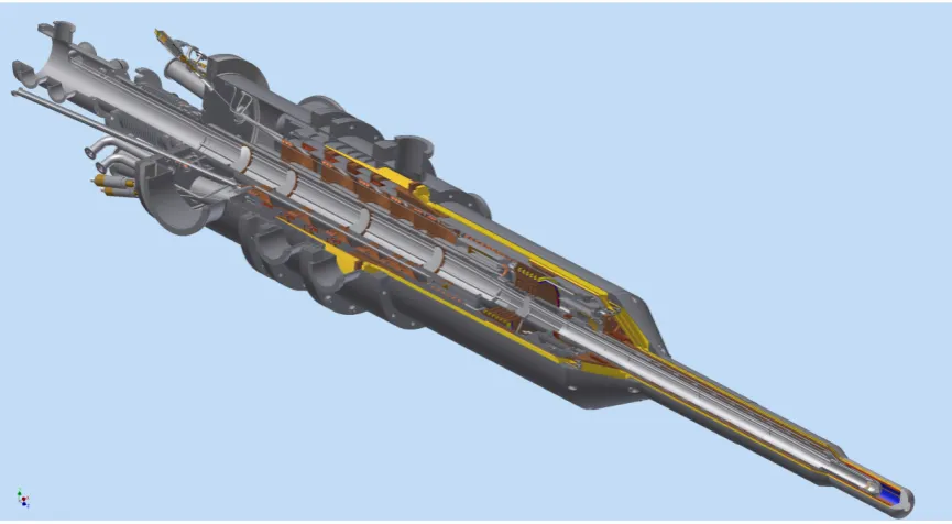
of liquid helium. The simulation of the precooling stages of the refrigerator is described in section 4. It is the first computational fluid dynamics (CFD) simulation of a di-lution refrigerator which takes all in- and backstreaming gases and fluids into account. The final heat exchanger and the still are in first order conditioned by the outer shape of the cryostat. From the outside, the system will look like a typical ’Roubeau - cryostat’, the cylindric mixing cham-ber which is surrounded by the internal polarizing magnet is followed by the final heat exchanger. The low temper-ature heat exchanger was designed and delivered by the low temperature working group of the JINR Dubna. It is a 10 staged large surface sintered copper heat exchanger with an expected base temperature of about 30 mK. To the backward region the diameter opens conical to the pump-ing tee. The smooth transition from the larger diameter of the 70 K region to the low temperature part of the cryo-stat allows one to use high temperature superconducing (HTSC)-current leads for the internal polarizing magnet. An additional heat sink cooled by a separated4He-circuit provide the required cooling power to cool the normal con-ducting current leads at the transition point to the HTSC down to 50 K. Taking the parameter of a standard HTSC wire into account, a maximum current of 120 A can be accepted for an internal magnet. A cut-view of the new dilution refrigerator is shown in Fig. 3.
3.3 Status
Figure 3: Cut view (technical drawing) of the new horizontal3He/4He dilution refrigerator
precooling stages in fall 2015. Subsequently we started with the overall assembling of the precooling units, the dilution unit (still and low temperature heat exchanger), cooling shields and the outer vacuum envelope to complete the refrigerator. The first cool down of the completed sys-tem is now foreseen for Sepsys-tember this year. We are still optimistic to get an innovative and reliable working dilu-tion refrigerator for a new class of (double) polarizadilu-tion experiments within the scheme of the so called ’4π contin-uous mode’ polarized target.
To cool down and cold test the refrigerator we have in-stalled a complete test facility in our traget laboratory to avoid conflicts and overlaps with experimental program of the Crystal-Barrel experimental at ELSA. The test set-up is identical with the one at the CB area and it allows us to operate the new dilution refrigerator under typical run con-ditions at the beam area. As soon as we have reached the designed parameters and a stable operation at reasonable parameter setting, we will dynamically polarize the target material by means of the internal superconducting polariz-ing magnet. Once we have successfully demonstrated the feasibility of the new target scheme, we will move the tar-get to the Crystal-Barrel experimental area for upcoming double polarization experiments.
4 CFD Simulations of the new dilution
refrigerator
4.1 Introduction
Parallel to the design and construction of the new dilution refrigerator we started a program to study in more detail the fluid dynamics of a dilution refrigerator more general. Here the precooling stages of the refrigerator were of spe-cial interest. Since only rough calculations of the vari-ous precooling stages and types of heat exchangers can be
found in the literature, we decided to perform a computa-tional fluid dynamics (CFD) simulation of the single units and the combined precooling stage. The goal of the CFD-simulations is to estimate the characteristic flow parameter for every in and out going stream and to simulate the heat exchange between them for a better insight to the opera-tional characteristics of this dilution refrigerator. Simula-tions for the different parts of the precooling stages were performed and will presented here in more detail [15].
4.2 The precooling stages
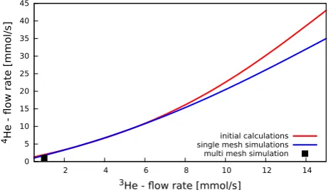
The precooling unit consists of two heat sinks and three heat exchangers which are shown in Fig. 4. One addi-tional heat exchanger is located in the second heat sink. It is called evaporator and is working at a temperature of 1.2 K. HE1 and HE2 have to precool the incoming coolant (highly concentrated3He gas (≈90%) and 10%4He im-purity at room temperature) by the usage of4He from the separator and the3He back stream coming from the still down to the separator temperature of 3.8 K. Fig. 6 shows the necessary4He flow rate to cool the incoming3He gas down to this temperature. HE3 is supported by the liquid 4He of the evaporator and liquefy the incoming coolant (3He gas). The heat exchanger in the evaporator should prevent the incoming stream from being cooled down to 1.2 K before it enters the dilution unit. Fig. 5 shows a flow scheme for the precooling unit.
HE1
Pr=0.7
Nu=3.66 HE2
Separator
HE3
Pr=0.7
Nu=3.66
Evaporator 300 K
3.8 K
1.5 K Figure 4: Sketch of the precooling unit
Figure 5: Scheme of the precooling unit and the different streams
the different streams through the solid
˙
Qsolid(ΔTm)=α·AΔTmwithα∝Nu(Re,Pr)·
λ L. (1) Nuis the Nusseltnumber, which depends on the Reynolds (Re) and the Prandtl(Pr) number [20]. These three values are used to characterize the stream behavior. Equation 1 shows that the heat exchange depends on the characteris-tic flow parameter, the geometry (the surfaceAand lenght Lof the heat exchanger as well as the thermal conductiv-ityλof the material) and the temperature differenceΔTm. Unfortunately it can be a great challenge to determine this numbers. For the initial calculations the Prandltand the Reynoldsnumbers for the backstreaming3He were esti-mated toPr =0.7 and Nu=3.66. For the other streams the fluid flows through tubes and the calculations from [18] were used, for the calculation ofReandPrsee [19].
4.3 CFD-Simulations
CFD simulations were performed to estimate the influence of the backstreaming3He-4He on the cooling power of the precooling stages. Almost all CFD simulations are based on [16, 17]
∂
∂t(ρφ)+∇ ·
ρ
uφ
Fφ
=Dφ+Qφ. (2)
whereupon ρis the density, φa fluid dynamic parameter (e.g. fluid velocityu, pressure p or temperatureT...),Fφ andDφ are the convective and the diffusive flow and Qφ represents all other distributions given by φ. For a com-pressible fluid this leads to the
• continuity equation
∂
∂t(ρ)+∇ ·
ρ
u=0, (3)
• momentum equation
∂ ∂t
ρ
u+∇ ·ρuu=∇ ·τ− ∇p+ρg, (4)
wheregrepresents body forces acting on the fluid con-tained in the control volume and τ the stress tensor which depends on viscous and pressure effects of the fluid.
• energy equation
Defining the specific enthalpy h = u + p/ρ and in-troducing Fourier’s law for heat transfer by conduction q =−k∇T, with the thermal diffusivityk = (μcP)/Pr, the dynamic viscosity μ, the specific heat at constant pressurecPand the Prandtl(Pr) number one can write the energy equation in the enthalpy form
∂
∂t(ρh)+∇ ·
ρ
uh=−∇ ·q+∂p ∂t +∇ ·
τ· u. (5)
Depending on the specific case additional conditions like the equation of state or different specific material equa-tions lead to a solvable problem. This simulaequa-tions were performed with OpenFOAM [23]. The meshes for the cal-culation were created with the including mesh generating code called snappyHexMesh. There are two possible ways of simulation:
the Nusseltand the Reynoldsnumber. These values characterize the thermal coupling between the fluid and the solid in a system and if the flow is laminar or turbulent. The simulation can be performed for all streams until the flow parameters are known. In ad-dition the characteristic flow parameters can be used to perform the calculations from section 4.2 again.
2. Multi mesh simulations:a simulation with a diff er-ent submesh for the calculation of the heat exchange between the different fluid streams and solids. This simulations are based on the solver chtMultiRegion-SimpleFoam[23].
By the usage of a multi mesh it is possible to set the boundary conditions for each stream in one simula-tion and run the solvers for each submesh represent-ing a solid or a fluid. In this case the data necessary for the connecting surfaces of the submeshes can be replaced in each iteration and couple the solvers for each region. With this method the heat exchange between the different streams of the heat exchanger can be calculated in one simulation.
For both solvers we added the low temperature data from [25–27] to the thermo physical library implemented in these solvers. The viscosity of the helium gas was modu-lated with the Sutherlandequation [20]. The heat capac-itycpwas assumed to be constant for the gaseous streams.
0 5 10 15 20 25 30 35 40 45
2 4 6 8 10 12 14
4He - ow rate [mmol/s]
3He - ow rate [mmol/s] initial calculations single mesh simulations multi mesh simulation
Figure 6: 4He flow rate necessary to cool the incoming coolant to the temperature of the separator
4.4 Single Stream Simulations
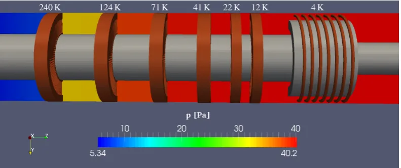
In the beginning single stream simulations of the 3He backstream were performed due to the lack of knowledge about the flow parameter of the backstream. Figure 7 shows the pressure and temperature gradient and the ve-locity profile as an example of this simulations. Here the backstream around heat exchanger 1, 2 and the separator is shown. The beamline and the outer wall are expected to be adiabatic. The massflow is set to 1 mmol s−1and the temperature is set to 3 K at the inlet. The heat transfer through the solids is given by the Fourierequation. For
this simulation a constant mean temperature given by the calculations of section 4.2 was estimated for each cooling stage. These initial boundary conditions for the tempera-ture are given in Fig. 7a.
The simulations were performed until a residual of≤10−7 for all parameters was reached. Due to the heat exchange between the different streams these single mesh simula-tions have to be repeated until convergence for the com-plete system is reached. It is also possible to extractRe, PrandNufrom these data. Afterwards the necessary4He flow-rate to precool the circulating coolant can be recalcu-lated, this is displayed in Fig. 6 by the blue line.
4.5 Simulation of a Heat Exchanger
Multi region simulations were performed to calculate the heat transfer between the different streams and the impor-tant flow parameters of a heat exchanger in one simulation. In Fig. 8 and 9 the pressure distribution for the incoming and outgoing 3He (coolant) is shown for HE2 as an ex-ample of this simulation. The temperature distribution for the different streams is given in Fig. 10 and 11. For the simulation shown in Fig. 8 to 11 a 3He circulation rate of 1 mmol s−1 was estimated. The inlet temperatures for the 3He backstream and the4He are set to 3.8 K, the in-let temperature of the incoming 3He is estimated to 5 K. The simulations for all heat exchangers of the precooling stages with the flow rates for the different operation modes are ongoing. With this data a prediction for the necessary 4He flow rate to precool the circulating3Heunder the in-fluence of the3He backstream at a given circulating rate can be done. Fig. 6 shows the prediction from the multi region simulations for the flow parameter of successfully completed simulations at this time. Now it is possible to access the velocity profile, the temperature and the pres-sure gradient for all parts of a heat exchanger within one simulation. This information can also be used to optimize the performance of the different cooling stages by chang-ing the geometry and by optimizchang-ing the flow impedances.
4.6 Conclusion
12 K 22 K 41 K 71 K
124 K
240 K 4 K
(a) Pressure distribution of the backstreaming3He
(b) Temperature distribution for the backstreaming3He
(c) Velocity profile of the backstreaming3He
Figure 7: Simulation of the3He backstream for HE1 and HE2 at a mass flow rate of 1 mmol s−1
5 Development of a thin, internal
superconducting polarization magnet
for the Polarized Target
5.1 Introduction
For improving the figure of merit of double-polarization experiments at CB-ELSA in Bonn the development of a novelContinuous Mode-Targethas been proposed in 2004
[14]. One key element for this concept is a thin, high field polarization magnet, which is placed within the refriger-ating structure. With such a magnet DNP could be used during the measurement of the experiment. A very first version of a ’thin high field internal magnet’ (total thick-ness 1.3 mm [28]) has been wound for the existing ’CB frozen spin target’ as holding coil and was in operation in nearly all double polarization measurements at ELSA.
inter-Figure 8: Pressure of the3He backstream in HE2
Figure 9: Pressure for the incoming3He stream (coolant) in HE2
Figure 10: Temperature of the incoming and the outgoing 3He stream in HE2
nal superconducting high field magnet, magnetic fields of 2 T are achievable in a thin coil with only 4 to 6 layers of superconducting wire at currents up to 100 A. But with regard to the homogeneity of the magnet, the test mea-surements led toΔB/B≈10−3, a more dedicated magnet simulation was required. The problems one has to deal with and which had to be solved within the simulation to improve the homogeneity are twofold. The specified min-imized dimensions of the solenoid yield a ration between the magnetic volume and the target volume only of 0.05 which presuppose a calculation with respect to the accu-racy of the positioning of the field correction elements as well as the positioning of each wire loop on the bobbin.
Figure 11: Temperature of the outgoing 3He and 4He stream in HE2
Finally one has to take the (limited) mechanical accuracy of the winding machine for the winding process of the su-perconducting wire into account.
The investigation of this problem in the framework of a diploma thesis has led to an ’inverse notched coil’ cor-rected solenoid for the design of the magnet [29]. The simulated solenoid consist of 6 layers of superconducting wire (Ø254μm) each with 590 windings. The corrector coils wound on the inner diameter of the solenoid (’inverse notched coil’) (Fig. 12) consists of 16 windings within 2 layers. At a nominal current of 90 A a maximum field of 2.5 T should be achievable. The calculated homogeneity is of the order ofΔB/B≤5×10−5.
The practical realization of the first design failed due to the limited mechanical accuracy of the winding process which was required to fulfill the high sensitivity of a stable solu-tion of the homogeneity calculasolu-tion. Therefore a new de-sign concept with respect to the winding accuracy on the bases of the existing coil design was needed [30, 31].
5.2 Boundary condition and design concept
A technical drawing of the basic coil carrier can be seen in Fig. 12. The overall thickness of 2 mm should not be exceeded otherwise the detecting threshold will be raised by absorption of particles in the structure. For the DNP process a magnetic field of 2.5 T is needed. To fulfill both requirements a superconducting wire1is used. The main field is created by a 6-layer solenoid with 586 windings per layer.
For polarizing deuterons the inhomogeneity (Eq. 8) of the field within the target area must be smaller thanΔB/B0= 10−4. Because the field of a perfect solenoid is not suffi -cient (ΔB/B0 >103), two correction coils are added. The homogeneity is very sensitive to any misalignment of these coils. In contrast to the Notched Solenoid [32], where the correctors are wound on the outer shell of the main solenoid, they are placed in the inner shell of the solenoid. Two notches in the bobbin give maximum preciseness for positioning the coils (Fig. 12). Hence this concept is called theInverse Notched Solenoid. Each correction coil has 2 layers with 9 windings each.
0.981 0.992
1.015 1.025
1.025 c=0.979
155.2
20
20 44.6
Notches
Figure 12: Sketch of the bobbin of an internal polarization magnet. The target area is located in the magnetic center. Within this area the magnetic field must fulfill the homogeneity criteria. The grey filled areas indicate the notches. The six values on the bottom side are the factorscused for the density calculation (see Sec. 5.4.2). Length-units are in mm.
The whole magnet has an inductance of 160 mH and a stored energy of 650 J at 2.5 T. The wires are fixed to the carrier structure by a cryogenic epoxy glue in a wet wiring process.
5.3 Calculation
5.3.1 Biot-Savart law
For calculating the magnetic field of a solenoid and its cor-rection coils the Biot-Savart-Law is used (eq. 6).
B(x0)=
μ0
4πI
(γ(t)−x0)× ˙ γ(t)
|γ˙(t)|
|(γ(t)−x0)|3 dt (6)
Figure 13 shows all necessary vectors for a certain path
γ(t). For this design the path is given by a loop parametrization (Eq. 7) withras the radius of each loop anddeff(effective diameter, see Sec. 5.3.2) as the distance between two wires.
γ=(rcos(t),rsin(t),n·deff) (7)
The product of the counting variablenand the effective di-ameterdeffgives the position of each loop. Due to the su-perposition principle the field of each loop may be added up to an overall field at a positionx0. To find the best po-sition of the correction coils an algorithm loops over all possible positions and calculates the maximum field inho-mogeneity (Eq. 8) within the target area. The central field B0=B(0) is used here as the reference value.
ΔB(x0) B0
= B(x0)−B0 B0
(8)
At the best position of the correction coils the field in-homogeneity can be calculated to ΔB/B0 < 0.4×10⁻⁴. Figure 14 shows the field map calculated for this case. The slight asymmetric structure comes from the fact that the magnetic center does not coincides with the geometric center. This is caused by the orthocyclic winding scheme (see fig.15) in combination of a constant loop number for each layer.
Figure 13: Electric current on a hectically path. The Biot-Savart law is used for calculating the magnetic fieldBat the positionx0.
5.3.2 Effective diameter
The effective diameter deff is defined as the distance
be-tween one wire and its neighbor. Because there is some space filled up with glue it does not coincide with the me-chanical wire diameterd. As can be seen in Fig. 15 [33], in orthocyclic wiring the wire forms an equilateral trian-gle withdeffas edge length. The effective diameter mainly
depends on the glue’s viscosity, the tensile stress and (lat-eral) pressing forces on the wire. The latter is caused by the hand tool which applies the glue onto the surface and the efficiency of the wire guiding mechanism.
5.4 First prototype
5.4.1 Estimation of the field homogeneity
Figure 14: Field map of the target area of the ’Inverse Notched Solenoid’.
de
d
Figure 15: Schematic drawing of an orthocyclic wiring.
is a significant discrepancy between the measured and the calculated field. An asymmetric structure with two local maxima can be seen near the position of the correction coils. From this data it is clear, that the criterion of homo-geneity has not been reached.
An explanation for this behavior can be found by a precise analysis of the wire position on the solenoid.
Figure 16: Comparison of the magnetic field measurement of the first and second prototype as well as the calculated (simulated) field for constant and distributed current den-sity of prototype 1. The grey filled rectangles illustrate the position and size of the two correction coils.
5.4.2 Density calculation
When calculating the magnetic field a homogeneous cur-rent density is assumed over the whole solenoid which presuppose a constant effective diameter. In practice the effective diameter can vary along the solenoid during the wiring process due to a non constant application of the glue to the wire. This lead to a local variation of the wire position compared to the calculated position and finally to a wire density variation which is equivalent to a local vari-ation of the current density.
A simple model considering this effect is introduced in Fig. 12. The solenoid is split up into 6 parts, where the ef-fective distance is modulated by a factorc. A factorc<1 means the effective diameter is reduced, the current den-sity in this region is raised. As it can be seen in Fig. 16 this simple model can reproduce the measured asymmetric structure by varying the effective diameter only by about 2 %. The mispositioning of the wires and the non constant effective diameters could be verified by an optical micro-scopic scan of the magnet surface. The position of each wire has been determined afterwards with high precision by an image analyzing system.
As conclusion from these measurements one have to state, that the local variation of the wire has to be reduced other-wise the homogeneity will be diminished.
5.5 Second protoype
The variation of the effective diameter could be reduced to a value better than 1 % by improving the wiring tech-nique. Most important for a high quality winding process towards an orthocyclic wiring (Fig. 15 is a high precision wire guiding. In our case we used a custom made tool to guide the wire with a constant lateral force toward its neighboring loop. The feed speed of the guide was ad-justed by a feedback control unit to the coiler speed, the viscosity of the used adhesive and the actual wired layer. All improvements of the new wiring technique lead to a second prototype of the "Inverse Noched Coil".
5.5.1 Estimation of the field homogeneity
5.5.2 Field measurement
The second prototype has been tested in liquid helium at 4.2 K with a current of 60 A. The magnetic field distribu-tion within the target area on the z-axis has been measured using a standard hall probe at a maximum field ofBmax= 1.65 T. The data are plotted in Fig. 16. In contrast to the first prototype there is, as expected, a flat plateau within the target area. But due to the known limited resolution of the hall probe the homogeneity of the solenoid could be estimated not better thanΔB/B0≤10−3.
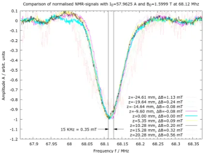
the field inhomogeneity was compensated by adjusting the current resp. magnetic field to align each peak to the cen-ter frequency. As it can be seen in Fig. 17 this align-ment could only be archived within a field band of about 0.35 mT around the center frequency. The field deviation
ΔBhas been calculated from this current adjustment. The maximum field deviation close to the margin of the tar-get area can be found at z=10.28mm and is of the order of 0.20 mT. With regard to the uncertainty of the align-ment the measurealign-ment lead to an estimated value for the homogeneity of aboutΔB/B0=3.5×10−4.
Figure 17: Normalized NMR-Signals of a polyethylene sample in thermal equilibrium in different positions within the magnet. All solid lines correspond to a position within the target area.
5.6 Conclusion
A thin, internal superconducting polarization magnet for the Polarized Target is actually in development. A mag-netic field of 2.5 T with a field inhomogeneity better than 10−4within the target area is necessary for the DNP pro-cess with deuterons. The basic concept - the Inverse Notched Solenoid - works with a solenoid for the main field and two correction coils which are added in the inner radius. This gives an accurate positioning of these correc-tion coils.
Tests with the first prototype showed that the field inhomo-geneity will definitely be influenced by a local variation of the wire position in the solenoid. To reduce the varia-tion and to improve the accuracy of the wire posivaria-tioning, a modified high precision wiring technique has been estab-lished. A second prototype has been build and passed first tests: The field measurement along the z-axis shows the expected flat plateau within the target area. NMR-Signals of polyethylene at 4.2 K could be seen with this magnet and indicate a sufficient homogeneity.
For the next step the magnet will be installed in our4 He-refrigerator. The maximum possible current will be deter-mined at 1 K. Additionally the magnet will be tested for dynamically polarizing a butanol-target.
Since the experimental program of the Crystal-Barrel
ex-periment at ELSA has foreseen the measurement of dou-ble polarization observadou-bles on transversely polarized tar-get nucleons, it is planed to design a combined coil pro-viding a longitudinal high magnetic field for the dynamic polarization process and a weak transverse magnetic field to maintain the polarization in the so called ’holding’ or ’frozen spin mode’ of the polarized target. First prelimi-nary design studies indicate the feasibility of this concept.
6 Polarization and relaxation
characteristics of irradiated polymeric
materials at 1 K and at 2.5 T
6.1 Introduction
Polymers have been discussed as candidates for solid state target material for at least the last two decades. Unlike the commonly used alcohols e.g. butanol or inorganics e.g. ammonia, polymer targets have a major advantage in the fact that they can be formed to practically any desired ge-ometry and can thus provide a filling factor close to 1. In addition, the materials are solid at room temperature and handling is unproblematic. The defining point of a good solid state target material is a high polarization of the pro-ton or deuteron components. The polarized target group at the Paul Scherrer Institute (PSI) showed dynamic nuclear polarization of protons in thin polyethylene (PE) foils and small tubes, chemically doped via diffusion of the highly stable free nitroxyl radical 2,2,6,6-tetramethyl-piperidine-1-oxyl (TEMPO) to a spin density of 2×10¹⁹spins/cm3, to values of 70% in a 2.5 T magnetic field at a temperature below 0.3 K [34, 35]. Ideally one would like to achieve polarizations in polymer materials comparable to the clas-sic materials of over 90%. It has also been proposed that the crystallinity of polymers may in fact be a major fac-tor in obtainable polarization values, as polarizations seem to be higher in amorphous materials than in crystalline materials at least with regards to chemically doped sam-ples [36]. Kumada et al. [37] showed that for PE doped in the same manner as the PSI materials this was indeed the case. Their EPR studies showed that the chemical dopant TEMPO only diffused into the amorphous regions of the polymer. Whether or not the crystallinity affects the polar-ization if the radicals can indeed permeate the crystalline region, as is the case if the materials are irradiated, is still an open question [38].
6.2 Polymer sample materials
single hydrogen atom and a CH3 group (CH2-CH-CH3 monomer - see Fig. 19). The arrangement of the chains can be amorphous, the chains are random and unoriented, crystalline, the chains are folded and packed, or more com-monly semi-crystalline in which crystalline structures are dispersed within the amorphous regions. Three diff
er-Figure 18: Polyethylene (CH2)n
Figure 19: Polypropylene (CH2-CH-CH3)m
ent types of polyethylene were used.The samples con-sisted of 1) highly amorphous, low density PE (LDPE) with lots of branching, 2) a low branching, high density PE (HDPE) with a high amount of linearly arranged chains (crystalline) and 3) linear low density PE (LLDPE), a high branching material interspersed with small crystalline re-gions. Polypropylene is differentiated by its stereo reg-ularity, the relative orientation of the CH2 and CH-CH3 groups. Three isotactic materials of varying chain length were used for which all the substituents are located on the same side of the macromolecular backbone.
6.3 Classification of samples after irradiation
To achieve high polarization of nuclei, DNP is used to transfer spin polarization from electrons to nuclei. In order for this to be possible electron spins must be introduced into sample materials e.g. by the creation of persisting structural defects by irradiation. In theory hydrogen ex-traction and chain scissions can occur, however the former is by far more likely in polymer materials. After the irra-diation the first step in the analysis of the materials is EPR spectroscopy. The comparison of the spectra of the irradi-ated material with spectra of a known spin density taken under the same experimental conditions gives access to the spin density of the irradiated material. This essentially tells us how many defects per unit weight were created in the irradiation process. Typical X-band spectra measured at a temperature of 77 K for PE and PP are given in fig-ures 20 and 21. The EPR spectrum also gives insight into the type of paramagnetic centers that have been created. Understanding the underlying radical structure can help to optimize the temperature dependent irradiation process with regards to polarization. An alkyl-type radical (see Fig. 22) is created in irradiated PE and gives the sextet of the EPR spectrum: The electron is localized on a p-orbital of the single carbon atom and has a hyperfine interaction with the single α- and four surrounding β-protons [39],
Figure 20: EPR of irradiated polyethylene.
315 320 325 330 335 340 345 350
-6 -4 -2 0 2 4 6
S
ign
al
[a
.u
]
Field [mT]
Figure 21: EPR of irradiated polypropylene.
Figure 22: Primary radicals created by irradiation of PE.
Figure 23: Primary radicals created by irradiation of PP.
of the material is thought to lead to a superposition of radi-cal structures that are primarily obtained by the removal of hydrogen atoms. In polypropylene there are 3 sites from which a hydrogen atom can be removed, each of which would be expected to give an individual and distinct EPR spectrum. A hydrogen atom can be removed from the car-bon backcar-bone opposite of the methyl group or from the methylene bridge, as well as from the side-chain methyl itself. The most likely explanation is the dominance of the alkyl-type radical shown in Fig. 23 with additional struc-ture resulting from the methyl group [41–44].
6.4 Preliminary irradiations at the LINAC1
0 20 40 60 80 100 120 140
0 1 2 3 4 5
Spin density [10
19 e - /g]
Time [min]
Figure 24: Decay of spin density in irradiated PP caused by heating of sample in nitrogen.
The electron irradiations in this study have so far been conducted in two consecutive data taking periods. Each of which will be described separately. The LINAC1 of the ELSA facility was used for the initial irradiation. A batch of PP pellets was irradiated in an argon cooled cryo-stat [45] and subsequently stored in liquid nitrogen. The initial spin density of the material was very close to 5 x 10¹⁹e−/g and in the order of magnitude in which one would typically expect DNP to be possible. As illustrated in Fig. 24 a subsequent heating of the samples in nitro-gen at room temperature leads to a significant drop in the spin density. The initial rapid decay of the alkyl-type rad-ical is followed by an almost stable region that lasts for some hours in which the alkyl-type radical is slowly con-verted into a allyl-type radical [46]. The conversion of the primary radical is evident from the slow increase of a sub-structure in the EPR spectrum, however the contri-bution of the latter to the spectrum on a whole is mini-mal and extremely difficult to extract due to the under-lying noise. In this regard it is to be expected that any change in polarization characteristics of the material by heating are related to the primary radical. Two of the char-acteristics of interest for target materials are the nucleon relaxation time and the maximum obtainable proton po-larization values. The change of these characteristics are shown in figures 25 and 26. Samples were analyzed at our standard4He-refrigerator experimental conditions at a
0 2 4 6 8 10
0 50 100 150 200
Relaxation time [min]
Heating time [min]
Figure 25: Relaxation times of irradiated PP after heat treatment.
0 2 4 6 8 10
4 6 8 10 12 14
Polarisation [%]
Heating time [min]
Figure 26: Polarization of irradiated PP after heat treat-ment
temperature of 1 K and a magnetic field of 2.5 T. Samples were heated for 2.5, 5 and 10 min. In these short peri-ods of heating the change of the relaxation times is enor-mous. The non heated sample has a relaxation time in the region of a minute in comparison to approximately 70 min for the sample heated for only 2.5 min. Additional heating increases the relaxation time further. The non heated sam-ple gave maximum polarization values of (4±0.2)%, with additional heating this was increased to (13.4±0.6)%. Unfortunately shortly after our introductory efforts the LINAC1 entered a prolonged period of maintenance and it was not possible to conduct any further irradiations of materials at this site: An alternative was needed.
6.5 Present irradiations at the LINAC2
energy of LINAC2 is slightly higher than that of LINAC1 with 24 MeV instead of 20 MeV, yet the beam intensity is 20x lower, meaning the irradiation times are significantly longer than in the previous irradiation of the polymeric materials (10 min), yet still not even close to the irradi-ation times of the non-organic materials such as NH3 or LiD (>10 h). A typical irradiation time needed to obtain a nominal spin density of 1019e−/g is conveniently in the region of a few hours.
As described in the previous section, a heat treatment of ir-radiated samples enhances the maximum polarization val-ues and increases the relaxation times. This positive effect should also be obtained by irradiating the materials above a material dependent specific temperature. In this way the “reorganization” of the electronic structure is obtained di-rectly during the irradiation. In 20 min the change of the heated sample is more or less completed by the transition of the primary radical into a quasi-stable state. In the case of an irradiation the same (or a similar) radical can be cre-ated over a period of a few hours in a much more con-trolled way. To find the optimal temperature of irradiation a wide range cryostat was used [47],[48]. The cryostat uses a dual regulating system, implementing a slow cycled liquid nitrogen cooled heat exchanger coupled to a closed helium gas system with a fast regulating 1000 W heater. In this way it is possible to irradiate samples at temperatures from 90 K to room temperature with a stability of ±1 K. The lower beam current of the LINAC2, in comparison to the LINAC1, works in favour of the temperature stability. At present the work is very preliminary as we have only recently gained access to the facility and a broad outline of the programme will be given. Three different polyethy-lene samples, differing in density and linearity, and 3 dif-ferent polypropylene samples, with varying chain length, have been irradiated simultaneously in the above men-tioned cryostat. This ensures comparability of the sam-ples: Any differences within a sample batch are thus due to differences in the materials. Irradiations were conducted at temperatures of 140 K, 180 K and 210 K. The injected charge of approximately 3 mC was sufficient to produce radical densities in the order of magnitude necessary for DNP.
As described in the previous section the first analysis of the materials was done with an EPR spectrometer and is summarised in Fig. 27. It was found that the spin den-sities of the different types of polyethylene are indistin-guishable at the irradiated temperatures and thus the aver-age was taken as a polyethylene batch. The same applies to the polypropylene samples. It is evident that the radi-cal production mechanism in polypropylene is much more effective and the yield of radicals was around 40% higher. Over the analyzed temperature range there is a drop in the radical yield to higher temperatures. This is likely mostly due to the temperature dependent recombination process of the primary alkyl radical, as well as the conversion into a secondary radical to a far smaller proportion. As with the heated samples the latter can be seen the in EPR spec-trum of the materials, however plays a subordinate role. The alkyl radical is still the dominant radical in all
spec-tra. The analysis of the polarization values of the irradi-ated samples at a temperature of 1 K and a magnetic field of 2.5 T is currently in progress.
140 160 180 200 220
0.8 1.0 1.2 1.4 1.6 1.8 2.0 2.2 2.4
Spin density PP Spin density PE
Spin density [10
19 e - /g]
Temperature [K]
Figure 27: Spin density of PP and PE after irradiation at various temperatures.
6.6 Conclusion
As has been proposed in many papers, polymers can be used in particle physics experiments in which high polar-ization values are obtained using DNP. To what extent the polarization values are adequately high for practical use in such experiments remains to be seen, but previous results from chemically doped samples in the past and current re-sults from the ongoing electron beam irradiations are very promising. The heating of the sample after irradiation has an effect on the relaxation and polarization characteristics of the samples. Significantly higher values of polariza-tion are obtained after heating the sample, whilst relax-ation rates become longer. The yield of radicals created as paramagnetic centers in PP by irradiation are in the region of 40% higher than in PE at the investigated irradiation temperatures. What influence the irradiation temperature has on the polarization characteristics is presently being studied: The change of the electronic structure initiated by heating should be obtained directly by irradiation at higher temperatures. Polarization measurements at very low tem-peratures are planned for the near future.
7 Development of a new Q-meter module
7.1 Introduction
[50].
For the operation and evaluation of measurements in parti-cle physics experiments with polarized solid targets a pre-cise knowledge of the sample polarizationPtis essential. This can already be seen by the so-called figure of merit
FOM∼ f2P2t ∼ 1 tmeas
(9)
of a polarized solid target, which characterizes the quality of the used target material with a dilution factor f2and is anti-proportional to the required measurement timetmeas for a given precision of these measurements.
In general, for the detection of target polarization the method of nuclear magnetic resonance is used. By means of a resonant circuit whose inductance is located in prox-imity to the sample, an alternating field is generated, which is oriented orthogonally to the external magnetic fieldB0. If the frequency of the alternating field matches the Lar-mor frequencyωLof the investigated spin system with the gyromagnetic factorγ,
ω=ωL=γB0 (10)
transitions between the Zeeman levels are induced. How-ever, this interaction only occurs for a narrow frequency range in the region of the Larmor frequency of the nuclei. Therefore, this effect is also called resonance absorption. Macroscopically, this results in a change of the sample magnetization, which is caused by the different occupied Zeeman levels of the sample.
Based on this change in magnetization, the NMR spectrum of the investigated sample can be determined. The areaA under the NMR line is proportional to the target polariza-tion
Pt=k·A (11)
with the so called enhancement factor3k.
7.2 NMR methods
In principle, there are two different methods for the de-tection of the NMR spectra of a sample. For the so-called pulsed NMR method, which is the current standard in many scientific fields, the sample magnetization is de-flected from its original position parallel to the external fieldB0by a short and powerful RF pulse. The subsequent relaxation of the magnetization back to equilibrium can be described by means of the Bloch equations [51, 52], lead-ing to a voltage induction into the NMR coil. This time-resolved voltage signal is commonly known as free induc-tion decay signal FID and can be converted by a Fourier transformation into the desired NMR spectrum. However, for the exact determination of polarization by this method there arise different problems, which are attributable to a 2The ratio of polarizable nuclei to the total number of nuclei in the
target material
3This factor is usually determined by a calibration in thermal
equi-librium, because the corresponding polarizationPt,T Ecan be calculated for a given magnetic field and a given temperature, so that a simple as-signmentk=Pt,T E/AT Ecan be made. This method is also called
TE-calibration
non-uniform signal excitation and a signal loss at the be-ginning of the FID detection.
Therefore, the well established continuous wave NMR technique is still the method of choice for the accurate de-tection of the undistorted NMR spectra and so for the mea-surement of the target polarization. Usually, this method is preformed at constant external field4 B
0, while the fre-quency of the applied radio-frefre-quency alternating field is swept over the resonance. Depending on the number and direction of the excited transitions between the Zeeman levels of the spin system, the power consumption or out-put of the resonant circuit changes. Since also the quality of the resonant circuit is affected, this set-up is also called Q-meter. The change of the quality of the resonant circuit can be detected as a variation of the radio-frequency power reflected from the oscillating circuit.
However, by this means there are two difficulties. On the one hand, radio-frequency signals are difficult to handle, on the other hand, the signal to detect consists of two sig-nal parts and is complex. Only the area below the imagi-nary part of the signal, the so-called absorptive signal com-ponent, is proportional to the target polarization Pt. To determine the amplitude of the radio-frequency signal one uses a diode detector followed by a low-pass filter which converts the RF signal to a DC signal proportional to the RF amplitude. For the detection of the absorptive signal component, a phasesensitive detector is used, which is in phase with the exiting signal.
7.3 Developement of a new cw NMR module
Therefore, the requirement for a newly developed cw NMR module for polarization detection of solid targets was given, which should serve as a substitute for the Liver-pool module. However, possible improvements should not be disregarded. To enable maximum compatibility with existing systems, the new development [54] is based in many ways on the construction of the Liverpool module. Specifically, these are the following:
• exciting RF signal via external generator
• two demodulation channels
– diode channel for receiving the magnitude spectrum and to tune the NMR resonant circuit
– phase-sensitive detector for the detection of the ab-sorption spectrum
• layout of the connector for power supply and signal transmission
• geometric dimensions of the module
The main differences between the modules can be at-tributed to various improvements and the necessary re-placement of no longer available components:
• outsourcing of the resonant circuit components – en-sures greater flexibility in experimental set-up of the measuring circuit (e.g.λ/2-cable)
4For the operation of a polarized target, this results in the advantage
that the necessary dynamic nuclear polarization frequencyωDNPis kept
• the capacitive elements of the resonant circuit have been replaced by a varicap diode – this allows electronic tun-ing of the resonant circuit and an access to a measure-ment based on synchronous resonance tuning (see [55])
• except the resonant circuit components, all components are on one circuit board with a system-wide impedance of 50 ohms – this allows a simple construction and repair of the modules, also possible signal reflections should be minimized
• replacement of the radio-frequency amplifier by com-mon models from Mini Circuits – good signal-to-noise ratio and price-performance ratio
• exchange of rectifier diodes - granted a higher linearity of this channel (see below)
To shield the components against internal and external noise, the boards were placed in specially designed hous-ings of solid brass, which were adjusted to each other.
7.4 Test measurements
For the warranty of functionality of the newly developed cw NMR module various test measurements were carried out. The most important ones are represented here briefly.
7.4.1 Linearity
A basic requirement for the exact detection of the target polarization over the area unitsAunder the NMR-line is only possible, if the amplification of the signals in the rele-vant performance range5is constant. Therefore, measure-ments at different frequencies6were performed to test the linearity of the two channels in this region. The NMR res-onant circuit was replaced by a variable attenuator, so that different input power levels (-62dBm to -31dBm) could be simulated.
Considering the resulting voltage profiles of the matched BRM channel in Fig. 28, a high degree of linearity can be seen in the work area for the different frequencies. The varying slopes between these traces at the given frequen-cies are due to different gains. This fact can be attributed to the frequency dependencies of the used components and is not important for the detection of the polarization at a fixed frequency.
Checking the linearity of the diode-channel based on BAT85-diodes, also used in the Liverpool module, there was a high deviation in a linear amplification at 212.6MHz. This effect could ultimately be attributed only to the diodes used. For this reason, various diodes were tested with respect to their linearity in the work region. It was found that the diode type SMS7630 which, accord-ing to data, is especially designed for mixers, shows the most promising behavior. Also measurements in the other relevant frequencies demonstrated the advantages of this type of diode, so that the linearity of this channel could be increased significantly.
5The input power of the NMR module during a polarization
measure-ment is, according to experience, at about -41dBm.
6Larmor frequency of deuterons and protons at 2.5 T and 5 T.
7.4.2 Detection of real spectra
In addition to linearity, the possibility for the exact detec-tion of the TE polarizadetec-tion plays an important role. For this reason, the TE signals of protons and deuterons of different samples were measured. As can be seen in Fig. 29, even smallest signals become clearly apparent from the predominantly white noise of the circuit, so that an exact determination of area units in the thermal equilibrium is possible.
A particular challenge for the polarization detection is represented by the TE signals of quadrupole broadened deuterons, since these spectra are split over a wide fre-quency range and the corresponding signal amplitudes are small. Nevertheless, as illustrated by fig. 30, also these spectra can be well detected with the new module, so that a polarization determination based on the TE method is possible.
By the characteristic waveform, which is for example de-scribed in [56], a further access to the polarization by the so-called asymmetry method is possible, directly from the line shape. Plotting the determined polarization against the respective area units, as shown in Fig. 30, leads to a linear correlation, where the slope is the known enhance-ment factor k. Comparing the two enhancement factors (kT E=12.22±0.57 andkasy=12.39±0.07) identified for this sample, shows no major contradictions and can thus be used for a confirmation of the correct operation of the module.
7.5 Conclusion
The various tests have shown that the newly developed cw NMR-module is ready for experimental use and even smallest signals can be well detected. First measurements were performed with a trityl-doped D-butanol target in Mainz and have shown no discrepancies. The high com-patibility with the Liverpool module also ensures an easy deployment in existing test set-ups, therefore an additional alternative for the polarization detection is available. Finally with the new NMR module we have build an exper-imental tool to measure the nucleon polarization with high presission for single or double polrization experiments. It will be the NMR ’standard’ for upcoming polarized target set-ups and polarization experiments.
8 Conclusions and Outlook
Figure 28: Measuring results for both channels for the observation of the linearity at selected frequencies. As can be seen, a constant gain of the diode channel based on BAT85 diodes was not given. However, by the exchange by SMS7630 diodes, the effect could be eliminated, so that both channels show a high degree of linearity in the measuring range at about 2mV input voltage (∼-41dBm input power).
Figure 29: NMR spectra of deuterons (6LiD @77K: P
t = 0.0007%) and protons (ammonia @1K: Pt = 0.255%) in thermal equilibrium at 2.5 T. As can be seen, even smallest signals can be well detected, enabling a sufficiently accurate measurement for a TE-calibration.