Available online:
https://pen2print.org/index.php/ijr/
P a g e | 505Performance Optimization of Mini-Jet Engine
PIONIQ Group#1, Than Swe#2
#Department of Propulsion and Flight Vehicles, Myanmar Aerospace Engineering University
Meiktila, Mandalay, Myanmar
1Ten Members Group 2Supervisor
Abstract - This paper describes optimization of specific fuel consumption (SFC) of mini-jet engine with two parameters: inlet Mach number (M1) and compressor pressure ratio (Pr). And also optimum design line is described. The designated mini-jet engine is 47 N in thrust, 62700 rpm in revolution, and 100 mm in diameter, 180 mm in length. The maximum thrust (F) is 75 N, maximum revolution (N) is 120000 rpm and maximum turbine inlet temperature (TIT, T05) is 900 K.
Keywords - mini-jet engine, optimization, optimum line, SFC, thrust, TIT
I. INTRODUCTION
A. Basic Principles
The study of propulsion is needed to explain mini-jet engine theory. Jet propulsion is a practical application of Sir Isaac Newton’s third law of motion which states that, “for every force acting on a body there is an opposite and equal reaction”. The verb propel is defined as “to drive, or cause to move, forward or onward”. Propulsion involves an object to be propelled plus one or more additional bodies, called propellant [1].
Fig. 1 Aircraft propulsion [2]
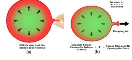
Jet propulsion is the propelling force generated in the direction opposite to the flow of a mass of gas or liquid under pressure. The mass escapes through a hole or opening called a jet nozzle. A familiar example is the nozzle at the end of a fire hose. An example of the theory of jet propulsion is an inflated balloon. With the opening in the balloon closed Figure 2a, there is no action because the pressure of the gas inside the balloon is equal in all directions. When you allow
the opening to release the air Figure 2b, the balloon moves. Its movements appear to be in all directions. However, it is always moving in the opposite direction from the open end where the air is exiting [3].
Fig. 2 Basic principle of jet propulsion [3]
Jet propulsion systems can be subdivided into two broad categories: airbreathing and non-airbreathing. Airbreathing propulsion systems include the reciprocating, turbojet, turbofan, ramjet, turboprop, and turboshaft engines. Non-airbreathing engines include rocket motors, nuclear propulsion systems, and electric propulsion systems [1].
B. Gas Generator
The "heart" of a gas turbine type of engine is the gas generator. A schematic diagram of a gas generator is shown in Fig. 3. The compressor, combustor, and turbine are the major components of the gas generator which is common to the turbojet, turbofan, turboprop, and turboshaft engines. The purpose of a gas generator is to supply high-temperature and high-pressure gas [1].
Fig. 3 Schematic diagram of gas generator [1]
C. Turbojet Engine
Available online:
https://pen2print.org/index.php/ijr/
P a g e | 506the use of fans, propellers, and shafts. By adding an inlet and a nozzle to the gas generator, a turbojet engine can be constructed. A schematic diagram of a simple turbojet is shown in Fig. 4.
Fig. 4 Schematic diagram of a turbojet [1]
The thrust of a turbojet is developed by compressing air in the inlet and compressor, mixing the air with fuel and burning in the combustor, and expanding the gas stream through the turbine and nozzle. The expansion of gas through the turbine supplies the power to turn the compressor. The net thrust delivered by the engine is the result of converting internal energy to kinetic energy [1].
D. Mini-Jet Enigne
The working principle of mini-jet engine is similar to full-sized turbojet engine. During operation the engine centrifugal compressor draws in air from its environs into the engine. The air is then compressed to increase its total pressure and temperature. The compressor diffuser increases the static pressure of the air and lowers its velocity as it passes through the diverging passages (vanes). The low velocity air mixes with fuel in the combustion chamber to burn continuously to produce high temperature, high pressure and velocity gas. The turbine expands the high temperature gas from the combustion process to produce mechanical shaft power to drive the compressor. The convergent exhaust propelling nozzle accelerates the exhaust gases from the turbine to create thrust for propulsion [4].
Fig. 5 Mini-Jet Engine
E. Uses
Small turbojet engine are developed for use in cruise missiles, target drones, and other small unmanned air vehicles (UAVs) [5]. Examples are Microturbo TRI 60 which different types (TRI 60-1, 60-2, 60-3, 60-5, 60-20, and 60-30) produce a thrust force ranging from 3.5 to 5.3 kN. This engine is a single spool, having a length of 851 mm (33.5 in), diameter of 348 mm (13.7 in), and dry weight of 61.2 kg (135 lb). March 20, 1983, represents the first-ever flight of a micro-turbojet powered model aircraft, which had a three-minute flight. This engine measured 4¾
״
in diameterand 13½
״
long and weighed 3¾ pounds. At 85000 rpm it produced over 9 lb of thrust and had a top speed of 97000 rpm. Twenty years later, commercial engines of roughly similar dimensions and weight are in the 30 lb thrust class when running at 120000 rpm. The airframe, with its twin-boom hightail configuration, is remarkably, perhaps inevitably, similar to many of today’s trainer aircraft. The first commercial micro-turbines were made available by JPX in the early 1990s [6]. Shortly after, Germany and the Netherlands sought out to develop a powerful, lightweight, liquid-fueled micro-turbine [5]. Other applications of mini-jet engines are auxiliary power unit (APU), Jet-man, flying hoverboard etc.F. Modern Trends and Current Challenges
Research works studied the effects compressor pressure ratio on thrust and other performance parameters [7]. In military applications there were special studies on the factors which determine the proper choice of engine cycle for a combat aircraft to suit the requirements of the designed mission [8]. Some researchers used energy and energy analyses with a turbojet engine over flight altitudes ranging from sea level to15000m to determine the relative effects of operating variables [9]. In mini-jet engine, air as the working fluid is used to produce thrust based on the variation of kinetic energy of burnt gases after combustion [10], [11]. Performance typically focuses on use of cycle efficiency, specific thrust, and specific fuel consumption [12], [13]. In addition, Pilavachi [14], Kaikko et al. [15], Katsigiannis and Papadopoulos [16], Nikpey et al. [17] and Caresane et al. [18] studied the use of mini-jet engine in typical cogeneration applications for heat production.
In aviation, engine fuel consumption and aircraft impacts on the environment are two important areas of research. From an environmental perspective, using energy with high efficiency reduces pollutant emissions and harm to ecological systems. For a given output, less fuel is needed when efficiency increases and less waste is released. These benefits lead to increased life times for energy resources and greater sustainability. [19], [20].
II. DESIGN METHODOLOGY
A. Working Cycle
Available online:
https://pen2print.org/index.php/ijr/
P a g e | 507analysis of real cycles, we will consider the behaviour of the realized turbojet engine including component losses, the mass flow rate of fuel through the components, and the variation of specific heats. Our analysis still assumes one-dimensional flow at the entrance and exit of each component. The variation of specific heats will be approximated by assuming a perfect gas with constant specific heat cpa
upstream of the main burner (combustor) and a perfect gas with different constant specific heat cpg downstream of the main burner. Block diagram and real cycle of mGT is shown Fig. 7 and Fig. 8 respectively.
Fig. 7 Block diagram of mini-jet engine
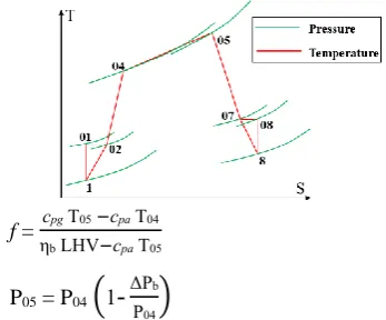
Fig. 8 Brayton cycle
From Fig. 7 and Fig. 8, section 1 and 8 are the static condition. In the intake section total temperature (T01 and T02)
are equal because of adiabatic process and also the nozzle section of the two total temperature (T08 and T07) are also
equal. At the compressor section, the compression takes place by the isentropic process that rises the pressure from P02 to P04. The combustion is done by isentropic expansion
which increase the temperature from T04 to T05 and that loss
the pressure by (P05-P04) which called the combustion
pressure loss. Turbine section also occurs isentropic expansion.
B. Modelling
The mini-jet engine was modelled by the following steps namely, intake, compressor, combustion chamber, turbine and nozzle sections the shown in Fig. 7 to get the performance parameters of specific fuel consumption and specific thrust.
1) Intake Section (1-2): An inlet reduces the entering air velocity to a level suitable for the compressor. The air velocity is reduced by a compression process that increases the air pressure. The operation and design of the inlet are described in terms of the efficiency of the compression process, the external drag of the inlet, and the mass flow into the inlet [22].
A1 =
π D12
4
T01 = T1+
c12
2cpa
P01 = P1
[
T01
T1
]
γa⁄γa-1
T02 = T01
P02 = P1
[
1+ ηiγa −1
2 M1
2
]
γa⁄γa-12) Compressor Section (2-4): The function of the compressor is to increase the pressure of the incoming air so that the combustion process and the power extraction process after combustion can be carried out more efficiently.
T04 = T02 +
T02
ηc
[
Prγa⁄γa-1
-
1]
P04 = Pr P02
3) Combustion Chamber Section (4-5): The combustor is designed to burn a mixture of fuel and air and to deliver the resulting gases to the turbine at a uniform temperature. The gas temperature must not exceed the allowable structural temperature of the turbine [1].
f = cpg T05−cpa T04
ηb LHV−cpa T05
P05 = P04
(
1-ΔPb
P04
)
4) Turbine Section (5-7): Turbines are a class of turbo machinery used to convert the energy in a flowing fluid into mechanical energy by the use of rotor mechanisms. Turbines, in general, convert either thermal or kinetic energy of the fluid into work to drive compressors [1].
T07 = T05−
cpa(T04−T02)
cpg ηm (1+f )
P07 = P05(
1-T05-T07
ηt T05)
γg⁄γg-1
5) Nozzle Section (7-8): The purpose of the exhaust nozzle is to increase the velocity of the exhaust gas before discharge from the nozzle and to collect and straighten gas flow from the turbine. In operating, the gas turbine engine converts the internal energy of the fuel to kinetic energy in the exhaust gas stream [1].The nozzle is needed to consider that is whether choked or not that depends on design consideration. However, most of mini-jet engine nozzles are unchoked.
Pc = P07
(
1−
[γg−1
ηj(γg+1)]
γg⁄γg-1
)
if Pc < P1 (Unchoked Nozzle)
P8 = P1
T8 = T07{1 – ηj [1-(PP8
07)
Available online:
https://pen2print.org/index.php/ijr/
P a g e | 508c8 = √2 cpg(T07−T8)
if Pc > P1 (Choked Nozzle)
P8 = Pc
T8 = T07
(
2 γg−1
)
c8 = √γg Rg T8
6) Performance Parameters: The main engine performance parameters are specific thrust Fs, specific fuel consumption SFC, thermal efficiency ƞT, propulsive
efficiency ƞP. These parameters were done by the following
equations.
Fs = a1[(1+f)
c8
a1-M1+(1+f )
Rg T8/T1
Ra c8/a1
1-(P1/P8)
γa ]
ṁa = ρ1 A1 c1
F = ṁa Fs
SFC = f
Fs ×3600
ηT =
a12 [(1+f )(ac8
1)
2 −M12]
2 f LHV
ηP = 2 c1 Fs
a12[(1+f )(ac81)2−M12] ηO = ηT ηP
C. Parametric Studies
Parametric cycle analysis is also called design point analysis or on-design analysis because each plotted engine is operating at its so-called design point. The main objective of parametric cycle analysis is to relate the engine performance parameters (primarily thrust F and thrust
specific fuel consumption S) to design choices (compressor pressure ratio, fan pressure ratio, bypass ratio, etc.), to design limitations (burner exit temperature, compressor exit pressure, etc.), and to flight environment (Mach number, ambient temperature, etc.). From parametric cycle analysis, we can easily determine which engine type (e.g., turbofan) and component design characteristics (range of design choices) best satisfy a particular need.
D. Inputs and Assumptions
Engine’s inlet Mach number (M1) and compressor’s
pressure ratio (Pr) are chosen as important parameters because the performance of engine is changing at different inlet conditions (M1, P1, T1), values of design choice (Pr),
design limit (T05).
The range of M1 is between 0.1-0.4 (0.4 is maximum
value in mini-jet engine). And the range of Pr is 1.2 to 4 (the small amount of thrust is produced at Pr=1.2 and 4 is maximum value for single stage centrifugal compressor).
Inlet static pressure and temperature are not considered as changing parameters at sea level and room temperature. The turbine inlet total temperature is chosen 900K because of materials limit. Also the sizing of inlet diameter is chosen as an input to know air mass flow rate. The fuel low heating value is also selected from type of used fuel.
After that, components’ efficiency, combustor total pressure loss, and specific values are assumed. The intake efficiency is 1 to neglect intake effect. The ranges of compressor and turbine efficiencies are normally between 0.8-0.87. Although the efficiencies of compressor and turbine are used as the lowest values because of technology availability. The 15% loss in combustor, 5% mechanical loss and 10% loss in nozzle are assumed. The values of parameters, inputs and assumptions are shown in Table 1.
TABLEI
INPUTS OF PARAMETRIC CYCLE ANALYSIS
III.RESULTS AND DISCUSSION
Parameters Inlet Mach number (M1) 0.1-0.4
Compressor pressure ratio (P04/P02) 1.2-4
Inputs
Inlet temperature (T1) 298 K
Inlet pressure (P1) 101325 Pa
Turbine inlet temperature (T05) 900 K
Assumptions Intake efficiency (ηi) 1
Compressor efficiency (ηc) 0.8
Turbine efficiency (ηt) 0.8
Exhaust efficiency (ηj) 0.9
Mechanical efficiency (ηm) 0.95
Combustor efficiency (ηb) 0.85
Combustor pressure loss (∆Pb/P04) 0.06
Available online:
https://pen2print.org/index.php/ijr/
P a g e | 509A. Variation of Thrust
Fig.9 Variation of Thrust with pressure ratio and Mach number
The variation of compressor pressure ratio (1.2-4), Mach number (0.1-0.4) and Thrust is shown in Fig. 8. Thrust increases when Mach number and pressure ratio are increased. But thrust decreases after the optimum pressure
ratio is reached. The optimum compressor ratio is 3, the maximum thrust is 75.0804N at M1=0.4.
B. Variation of SFC
Fig. 10 Variation of SFC with pressure ratio and Mach number
Fig. 10 shows the SFC variation with compressor pressure ratio and inlet Mach number. In this figure SFC decreases when pressure ratio is increased, and Mach number is fixed. When the pressure ratio is fixed and changing Mach number, the SFC increases. The minimum SFC is found at maximum pressure ratio and minimum Mach number.
C. Variation of Thrust and RPM
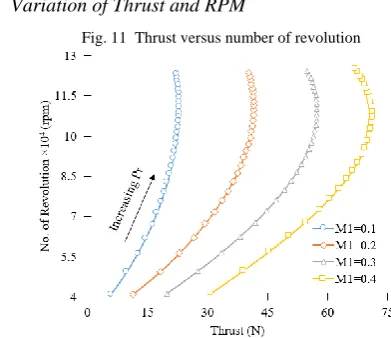
Fig. 11 Thrust versus number of revolution
This Fig. 11 is achieved by parametric cycle analysis and impeller design calculation. The number of revolution is calculated impeller design. The effect of pressure ratio and Mach number on thrust and number of revolution is shown in Fig. 11. By increasing Mach number, increasing thrust and rpm. By increasing pressure ratio, increasing thrust and rpm until optimum pressure ratio points. Beyond this points, increasing rpm but decreasing thrust.
D. Performance Optimization
The optimization of engine performance is the investigation of maximum thrust and optimum SFC for every operating conditions. This investigation is done with four parameters (M1, Pr, F, SFC). This engine performance
optimization is a part of parametric cycle analysis.
Fig. 12 Variation of SFC and thrust with Mach number and pressure ratio
Fig. 12 shows the variation of SFC and thrust with Mach number and compressor pressure ratio. When the Mach number is increased, both SFC and thrust increase. By increasing pressure ratio, SFC decreases and thrust increases. For each Mach number, there have an optimum pressure ratio that is the point of maximum thrust and optimum SFC. When the optimum points for every Mach number are connected, the optimum pressure ratio line was achieved. This is the optimization method of mini-jet engine for maximum thrust and optimum SFC. The optimum points are shown in Table 2.
TABLEIII
OPTIMUM POINTS OF MAXIMUM THRUST AND OPTIMUM SFC
IV.CONCLUSIONS
Firstly, variations of performances were investigated with inlet Mach number (M1) and compressor pressure ratio (Pr).
From these investigations, optimum pressure ratio was found with different conditions. The optimum point was designated
M1 Pr F (N) SFC (kg/N.hr)
0.1 3 23.9518 0.1875
0.2 3.1 43.6633 0.2064
0.3 3.2 60.3606 0.2241
Available online:
https://pen2print.org/index.php/ijr/
P a g e | 510for maximum thrust and optimum SFC at a flight condition. When the optimum points were connected, the optimum line was achieved at different flight conditions. This optimization method is very useful and helpful for better engine performance.
ACKNOWLEDGMENT
Our project group, PIONIQ would like to acknowledge our supervisor, U Than Swe and our co-supervisor, Dr. Kyaw Shwin for many insightful conversations and comments. The author expresses appreciation for the criticism of the referees, as a way of improving this paper. This project was supported by MAEU.
REFERENCES
[1] Jack D. Mattingly, Elements of Propulsion: Gas Turbines and
Rockets, foreword by Hans von Ohain.
[2] Rolls-Rayce Plc: The Jet Engine, 5th edition, 1986.
[3] Peter Spittle: Gas Turbine Technology, 2003.
[4] F Opponga, S.J van der Spuy, T.W. von Backström, A.Lacina Diaby,
An Overview on the Performance Investigation and Improvement of Micro Gas Turbine Engine, ResearchGate, March 2017, DOI: 10.13140/RG.2.2.10055.09123.
[5] Ahmed F. El-Sayed, Fundamentals of Aircraft and Rocket
Propulsion, Springer-Verlag London 2016.
[6] Lobik DP (1995), Unmanned aerial vehicles: a study of gas turbine
applications, M.Sc. Thesis, Naval Postgraduate School
[7] J. Yin, P.Pilidis, K.W.Ramsden, S.D.Probert, “Assessment of
Variable-Cycle Propulsion Systems for ASTOVL,” Aircraft Engineering and Aerospace Technology, 72(2000) 537–544.
[8] R.M. Denning, N.A. Mitchell, “Trends in Military Aircraft
Propulsion,” Aerospace Engineering, 203 (1989)11-23.
[9] S.C. Kaushika, R.V. Siva, S.K. Tyagib, “Energy and Exergy
Analyses of Thermal Power Plants,” Review, Renewable and Sustainable Energy Reviews 15(2011)1857–1872.
[10] Y.A. Cengel, M.A. Boles, “Thermodynamics an Engineering
Approach,” 7th ed., Mc-GrawHill, 2007.
[11] F Noori, M Gorji, A. Kazemi, H. Nemati, “Thermodynamic
Optimization of Ideal Turbo Jet with After Burner Engines Using Non Dominated Sorting Genetic Algorithm II ,” Aerospace Engineering 224 (2010) 1285–1296.
[12] N.U. Rahman, J.F. Whidborne, “A Numerical Investigation into the
Effect of Engine Bleed on Performance of a Single- Spool Turbo Jet Engine,” Aerospace Engineering, 222(2008) 939–949.
[13] A. Cavcar, M. Cavcar, “Impact of Aircraft Performance Differences
on Fuel Consumption of Aircraft in Air Traffic Management Environment,” Aircraft Engineering and Aerospace Technology, 76 (2004) 502–515.
[14] Pilavachi PA, “Mini- and Micro-Gas Turbines for Combined Heat
and Power,” Applied Thermal Engineering. 2002; 22: 2003-14.
[15] Kaikko J, Backman J, “Technical and Economic Performance
Analysis for A Microturbine in Combined Heat and Power Generation,” Energy. 2007; 32:378 - 87.
[16] Katsigiannis PA, Papadopoulos DP, “A General Technoeconomic
And Environmental Procedure For Assessment Of Small-Scale Cogeneration Scheme Installations: Application To A Local Industry Operating In Thrace, Greece, Using Microturbines,” Energy Conversion and Management. 2005; 46:3150-74.
[17] Nikpey H, Assadi M, Breuhaus P, “Development of an Optimized
Artificial Neural Network Model for Combined Heat and Power Micro Gas Turbines,” Applied Energy. 2013; 108:137-48.
[18] Caresana F, Pelagalli L, Comodi G, Renzi M, “Microturbogas
Cogeneration Systems for Distributed Generation: Effects of Ambient Temperature on Global Performance and Components’ Behavior,” Applied Energy. 2014; 124:17-27.
[19] A. Gohardani, S. Georgios, and R. S. Doulgeris, Challenges of future
aircraft propulsion: A review of distributed propulsion technology and its potential application for the all electric commercial aircraft, Progress in Aerospace Sciences, vol. 47, no. 5, pp. 369-391. 2010.
[20] IPCC, IPCC special report on aviation and the global atmosphere,
Intergovernmental Panel on Climate Change, 1999.
[21] F Opponga, S.J van der Spuy, T.W. von Backström, A.Lacina Diaby,
![Fig. 4 Schematic diagram of a turbojet [1]](https://thumb-us.123doks.com/thumbv2/123dok_us/1906717.1249791/2.595.312.543.693.751/fig-schematic-diagram-turbojet.webp)