PET SNAKE: A Special Purpose Architecture
to Implement an Algebraic Attack in Hardware
Willi Geiselmann1, Kenneth Matheis2, and Rainer Steinwandt2
1
Institut f¨ur Kryptographie und Sicherheit, Fakult¨at f¨ur Informatik, Universit¨at Karlsruhe (TH), Am Fasanengarten 5, 76128 Karlsruhe, Germany,
2Department of Mathematical Sciences, Florida Atlantic University, 777 Glades Road, Boca Raton, FL 33431,{rsteinwa, kmatheis}@fau.edu
Abstract. In [24] Raddum and Semaev propose a technique to solve sys-tems of polynomial equations overF2as occurring in algebraic attacks on block ciphers. This approach is known asMRHS, and we present a special purpose architecture to implement MRHS in a dedicated hardware de-vice. Our preliminary performance analysis of thisParallelElimination
TechniqueSupportingNiceAlgebraicKeyElimination shows that the use of ASICs seems to enable significant performance gains over a soft-ware implementation of MRHS. The main parts of the proposed archi-tecture are scalable, the limiting factor being mainly the available band-width for interchip communication. Our focus is on a design choice that can be implemented within the limits of available fab technology. The proposed design can be expected to offer a running time improvement in the order of several magnitudes over a software implementation. We do not make any claims about the practical feasibility of an attack against AES-128 with our design, as we do not see the necessary theoret-ical tools to be available: deriving reliable running time estimates for an algebraic attack with MRHS when being applied to a full-round version of AES-128 is still an open problem.
Keywords:block cipher, algebraic attack, cryptanalytic hardware, MRHS
1 Introduction
Algebraic attacks have become an important cryptanalytic tool, and the security of major cryptographic algorithms relies on the infeasibility of solving certain systems of polynomial equations. Popular approaches for dealing with such systems of equations are based on the use of Gr¨obner basis techniques and SAT-solvers—prominent examples including Buch-mann et al.’s discussion of AES-128 [9] and Courtois et al.’s discussion of KeeLoq [11]. Adding to the toolbox of algebraic cryptanalysis, in [24]
Raddum and Semaev propose a technique known as MRHS (Multiple
This algorithm is particulary well-suited for describing systems of equa-tions for an algebraic key recovery attack against common block ciphers such as AES or DES.
A full running time analysis of MRHS is to the best of our knowledge not available, but the observed performance in software seems quite favor-able, and in comparison to algebraic attacks involving the computation of a Gr¨obner basis, the required amount of memory seems easier to predict. Given arbitrarily large amounts of memory, MRHS should in principle be able to solve large systems of equations, but this is obviously not prac-tical. Consequently, the hardware architecture we propose builds on an adaption of MRHS where the amount of memory is fixed. The specific design choices made are motivated by the limits of currently available fab technology, and the scalability of major components should facilitate the construction of small prototypes with technology that is available at moderate cost.
Our contribution. We propose an ASIC design for implementing MRHS, which according to our analysis enables significant performance gains compared to an MRHS implementation in software. Owing to the mod-ular design and scalability, we think the proposed architecture to be of considerable interest when trying to mount algebraic attacks on relevant block ciphers. Building on a 45 nm manufacturing process, already a mod-erately sized network of chips of standard size seems capable of coping with rather non-trivial systems of equations. Our architecture is certainly far from optimal, and we hope that the promising results obtained so far stimulate further research along this line. Certain components of the architecture, specifically those for row reduction and multiplication of matrices over F2, might be of independent interest.
Sieve: For the row reduction overF2 we modify the linear algebra design SMITH of Bogdanov et al. [6, 7] to enable a more efficient handling of sparse matrices as occurring in the context of MRHS. (Note that SMITH has enjoyed previous success in [4].) The resulting JONES (Justifiable Optimization Neatly Enhancing SMITH) device might be of indepen-dent interest for other applications involving sparse matrices over F2.
The overall data flow in our architecture is remotely reminiscent of the systolic linear algebra design in [15], a main difference being the emphasis on a two-dimensional data flow. Two-dimensional data flows are well-known from special purpose designs for the Number Field Sieve, like [3, 20, 16], but the organization of the data flow in the new design is quite different and explains the choice of the acronym PET SNAKE for our architecture.
Structure of the paper. We start with a brief discussion of MRHS where we detail the variant of the algorithm underlying our proposal. Section 3 gives a description of the overall architecture we use. The overall architec-ture uses several identical copies of amain processing unit whose various components are explained in Section 4. Further details on the individ-ual components are given in the appendix. Finally, Sections 5–7 analyze the expected performance of the complete device, comparing it with a software implementation of MRHS.
2 Preliminaries: Multiple Right Hand Sides (MRHS)
For a detailed discussion of MRHS, we refer to Raddum and Semaev’s work [24]. Here we restrict to an informal review of those aspects of the MRHS technique which are needed to explain the proposed hardware architecture. In particular, we do not discuss how to set up an MRHS system of linear equations to mount an algebraic attack on a block cipher like AES-128 [21] and refer to [24, Section 6] for more details on this (cf. also [22] and [25, Chapter 5]). In our software experiments we worked with a reduced round version of PRESENT [5]. The derivation of the pertinent MRHS system is fairly standard—we do not claim any relevant originality for this, and omit the somewhat tedious details.
2.1 Basic Terminology
Let x := (x1, . . . , xy)t be a column vector consisting of y Boolean
variables,A ak×y matrix of rank k, andb1, b2, . . . , bs column vectors of
lengthk. An equation
Ax=b1, b2, . . . , bs (1)
is called an MRHS system of linear equations with right hand sides b1,
b2, . . . , bs. Asolutionto (1) is a vector inFy2satisfying one of the particular linear equation systemsAx=bi. The set ofall solutions to(1) is the union
of solutions to the individual linear systems Ax=bi (i= 1, . . . , s). In an
effort to manipulate the data contained in the above column vectorsbi, we
write them side-by-side to form a matrix L and rewrite Equation (1) as
Ax= [L]. The brackets aroundLemphasize that we are not working with a regular equation of matrices, and instead of the termMRHS system of linear equations the term symbol is often used.
Given a system of symbols
S1:A1x= [L1] .. .
Sn:Anx= [Ln]
, (2)
by asolution to such a system we mean a vector inFy2 satisfying all of the underlyingnMRHS systems of linear equations (wherex= (x1, . . . , xy)t).
The goal of the algorithm discussed next, and consequently of the PET SNAKE design below, is to find all solutions of (2).
2.2 Solving a System of Symbols
There are three main steps, to which we refer as agreeing, gluing, and
equation extraction. The proposed PET SNAKE architecture exploits sim-ilarities between these algorithmic building blocks for reusing hardware components—therewith reducing the area complexity of the design.
Agreeing of symbols The basic approach is to remove some of the columns bin a right hand side Li, if no one solution ofAix=bcan be a
solution to the System (2). The mechanism by which this is achieved is pairwise agreeing of symbols. Namely, let Si :Aix= [Li] and Sj :Ajx=
[Lj] be two symbols. ThenSi andSj agree if for everyb∈Li, there exists
a b0 ∈Lj such that the linear system
Ai
Aj
x=
b b0
is consistent, and, vice versa, for each b0 ∈Lj there exists a b∈Li such
that (3) is consistent.
WhenSiandSjdo not agree, one removes those columnsbfromLifor
which the linear systemAix=b is inconsistent with Ajx= [Lj]. Dually,
those columnsb0 fromLj are removed, for whichAjx=b0 is inconsistent
with Aix = [Li]. Different strategies can be used for this approach, and
for the design of PET SNAKE we follow the technique in Figure 1 (see [24, Section 3]) and realize it with a specialized hardware architecture.
1. Produce a nonsingular transform matrixU =Uij of sizet×tsuch that the product U A is a matrix with zeroes in its last r = rij rows and of rankt−r. Ifr= 0, the symbols agree.
2. Ifr >0, then compute the matricesU Tij andU Tji. LetP rij denote the set of ofU Tij-column projections to the lastrcoordinates. IfP rij=P rji, the symbols agree.
3. IfP rij 6= P rji, first remove all columns from Li whoseU Tij-associated column is such that its last-r-coordinate projection is not found inP rji. Name the resulting matrixL0i. Then similarly remove columns fromLjand name the resulting matrix L0j. The symbolsAix= [L0i] and Ajx= [L0j] agree.
Fig. 1.Agreeing two symbols Aix= [Li] andAjx= [Lj], where Lη ∈ Fk2η×sη. Here
A := Ai
Aj
is the vertical concatenation of Ai and Aj, i. e., A has t:=ki+kj rows. SimilarlyTij:= L0i
andTji:= L0
j
havetrows each.
It is important to note that if two symbols Sh and Si agree, but Si
and Sj disagree, columns may be deleted in one or both of Li and Lj.
After this happens, it is possible for Sh to disagree with either of the
modified symbols, and soSh will have to bere-agreed with them. During
that agreement, columns from Lh may have to be deleted, and so on. In
this manner, a chain reaction of column deletions may occur. Hence, in order to ensure that a system of symbols gets to a pairwise-agreed state, in PET SNAKE we perform theAgreeing1 Algorithmin Figure 2 (see [24, Section 3.1]).
While the symbols in a System (2) do not pairwise agree,
1. findSiandSj which do not agree
2. agreeSiandSjwith the agreeing procedure in Figure 1.
Fig. 2.Agreeing1 Algorithm.
Si : Aix = [Li] and Sj : Ajx = [Lj] is a new symbol Bx = [L] whose
set of solutions is the set of common solutions to Aix= [Li] and Ajx=
[Lj]. Once this new symbol is formed, it is inserted into the system and
the two symbols Si and Sj which formed it are no longer necessary and
hence removed from the system. Obtaining the matrix B is easy: with the notation in Figure 1, B is just the submatrix ofU A in its last t−r
nonzero rows. The matrixLhast−rrows and the columns are formed by adding one column fromU Tij to one column fromU Tji. More specifically,
we add a column from U Tij and one from U Tji, if they have the same
projection to the last r coordinates. Reducing the sum to its first t−r
coordinates yields a column of L, and forming all such matching pairs yields the complete matrixL. Gluing two matricesLi,Lj of widthsi and
sj may result in anL with as many as si·sj columns. Consequently, we
may not be able to afford to actually compute certain glues, and instead restrict to gluing only pairs of symbols where the number of columns in the resulting symbol does not exceed a certainthreshold.
Once several pairs of symbols have been glued, the resulting system will usually not be in a pairwise-agreed state, so the Agreeing1 Algorithm in Figure 2 can be run again, initiating another round of agreeing and gluing. The eventual goal of successive agreements and gluings is to obtain a system of symbols consisting only of a single symbol.
Equation Extraction From a given Symbol S : Ax= [L], where L ∈
Fk2×s, we can try to extractURHS (UniqueRight HandSide) equations: choosing an appropriate nonsingular transformation matrixV of sizek×k, the productV Lis upper triangular with zeroes in its lastrrows. Denoting by P r the matrix formed by the V A-column projections to the last r
coordinates, we obtain the r linear equations P r·x = 0. Next to these homogeneous equations, it may be possible to extract a nonhomogeneous linear equation: from the upper triangular matrix V L we can read off if the all-one-vector (1, . . . ,1) is in the span of the rows ofL. If this is the case, we obtain the nonhomogeneous linear equation (zA)x= 1, where z
is a row vector of length k such that zL = (1, . . . ,1). The resulting r or
r+ 1 URHS equations can be combined into agather symbol which then can be added to the system of symbols under consideration.
system of symbols—to which we will refer as state—is stored. Then the guess is performed by constructing a new symbol whoseApart is one row of all zeroes except for a single 1 in the position of the guessed variable, and whoseL part is a single value, either 0 or 1, depending on the value of the guess. Such a symbol is inserted into the system, and then pairwise agreeing, computation of URHS equations, and gluing continue as normal. If after some steps the state, again, does not allow any URHS equation to be extracted or pair of symbols to be glued, the state is again saved and another guess is committed.
Of course it is possible that in this process a guess for a variable is incorrect. This discovery manifests in the following manner: during the agreement of two symbols, all right hand sides of at least one of the symbols get removed. When this happens, the state must be rolled back to a previous state, and a different guess must be made. The practice of guessing variables, then, follows something akin to a depth-first search.
2.3 Implementation Choices
Fundamental design parameters for the PET SNAKE architecture have been chosen in such a way that it is possible to host a complete system of symbols as needed for a key recovery attack on a modern block cipher like AES-128. For AES-128 specifically, the pertinent system of symbols involves 1,600 variables, and the initial system requires only 320 symbols. (As comparison, for PRESENT, which has 31 rounds, the initial system consists of more than 500 symbols, and also the number of variables is higher than for AES-128). In general, handling systems with no more than 212 symbols still seems within the reach of PET SNAKE, and up to 2047 variables can be handled. For gluing symbols, we chose our threshold to be 220 right hand sides. This seems a nice balance between the upper limits of software implementations and the upper limits of current hardware storage abilities. In light of the multiplicative nature of the growth of right hand sides during gluing, giving one or two more powers of 2 to the threshold does not seem to readily contribute to a significantly reduced running time.
be comprised of nothing but full-size (that is, 257 MB) symbols, so it will almost always be possible to store more than 100 states; 400 or more states are not unlikely.
3 Overall Architecture
A complete PET SNAKE architecture consists of a several interconnected boards with each board hosting severalMainProcessing Units (MPUs). Each MPU is comprised of a small group of chips wired in a particular way, and there arep×psuch MPUs placed in a grid across the individual boards, wherep= 2λ is a power of 2. Subsequently we useλ= 5, yielding a total of 25·25 = 1024 MPUs, but the proposed architecture scales within reasonable limits; depending on the resources available, other parameter values, likep2= 28 might be an interesting option.
Each MPU can communicate with its north, south, east, and west neighbor MPUs (with no wraparound). For directing the action of the
p2 MPUs, a single Master ControlProcessor (MCP) is used. The MCP will make most of the decisions regarding which symbols to send where, which symbols to glue, and when to guess a variable.1 The MCP, which sits in a north corner, hasagents which sit at the north end of the board, one per column. Each agent has a southbound bus that connects to each MPU in that column via ‘hops’ between MPUs, so each off-chip part of the bus is short. Each agent communicates to the MCP horizontally via ‘hops’ between agents. Figure 3 gives a schematic view of the overall architecture.
3.1 Initialization
The initial system ofnsymbols is derived from a particular known (plain-text, ciphertext)-pair, and a solution to the system of symbols yields a secret key for the attacked symmetric cipher that is consistent with the particular (plaintext, ciphertext)-pair. The symbols are loaded onto the
p2 MPUs as evenly as possible. Let g be the number of symbols stored in each MPU—should the symbol count not be evenly divisible by the number of MPUs, we imagine empty symbols to fill in the gaps. Now imagine labelling each symbol in each MPU with a number in{1, . . . , g}. We call all symbols labelled with the same number a snake. Hence we have g snakes. If at this point g = 1, we halve the number of MPUs to
1
MPU MCP Agent 56 MPU 1 02 4 56 1024 56
Agent 56 Agent 56 …Agent 56
MPU 1024 56 MPU 1024 56 … MPU 1024 5 6 … MPU 5 6 … MPU 5 6 MPU 1 02 4 56 1024 MPU 10 2 4 5 6 1024 MPU 10 24 56 1024 MPU 10 24 56 1024 MPU 10 2 4 5 6 1024 10 24 56 10 24 56 10 24
56 56
… … … …
… MPU MPU 1024 MPU 1024 MPU 1024
10 2 4 10 2 4 10 2 4
Fig. 3.Overall architecture of PET SNAKE.
use, redistribute the symbols to this half, and try again; we continue this process until g = 2. The collection of MPUs now occupied with symbols is called the active area for this computation. Any inactive MPUs will be taken advantage of with parallelism, discussed later. The MCP deter-mines a Hamiltonian cycle through all MPUs, i. e., a path through all the MPUs such that one can move from one MPU to one of its neighbors in a closed circuit, without visiting the same MPU twice. The MCP will do the same for smaller groups of MPUs:p×p2, p2×p2, p2×p4, etc.—all the way down to 2×1. This data can be hardwired into the MCP, and we may assume that the MCP knows a path for each possible size active area.
3.2 Processing of Symbols
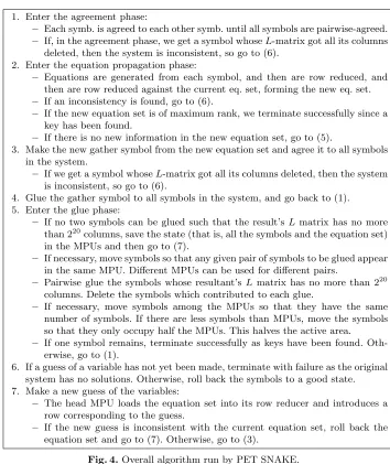
1. Enter the agreement phase:
– Each symb. is agreed to each other symb. until all symbols are pairwise-agreed.
– If, in the agreement phase, we get a symbol whoseL-matrix got all its columns deleted, then the system is inconsistent, so go to (6).
2. Enter the equation propagation phase:
– Equations are generated from each symbol, and then are row reduced, and then are row reduced against the current eq. set, forming the new eq. set.
– If an inconsistency is found, go to (6).
– If the new equation set is of maximum rank, we terminate successfully since a key has been found.
– If there is no new information in the new equation set, go to (5).
3. Make the new gather symbol from the new equation set and agree it to all symbols in the system.
– If we get a symbol whoseL-matrix got all its columns deleted, then the system is inconsistent, so go to (6).
4. Glue the gather symbol to all symbols in the system, and go back to (1). 5. Enter the glue phase:
– If no two symbols can be glued such that the result’s Lmatrix has no more than 220columns, save the state (that is, all the symbols and the equation set) in the MPUs and then go to (7).
– If necessary, move symbols so that any given pair of symbols to be glued appear in the same MPU. Different MPUs can be used for different pairs.
– Pairwise glue the symbols whose resultant’sL matrix has no more than 220 columns. Delete the symbols which contributed to each glue.
– If necessary, move symbols among the MPUs so that they have the same number of symbols. If there are less symbols than MPUs, move the symbols so that they only occupy half the MPUs. This halves the active area.
– If one symbol remains, terminate successfully as keys have been found. Oth-erwise, go to (1).
6. If a guess of a variable has not yet been made, terminate with failure as the original system has no solutions. Otherwise, roll back the symbols to a good state. 7. Make a new guess of the variables:
– The head MPU loads the equation set into its row reducer and introduces a row corresponding to the guess.
– If the new guess is inconsistent with the current equation set, roll back the equation set and go to (7). Otherwise, go to (3).
Fig. 4.Overall algorithm run by PET SNAKE.
Before going into details of the overall algorithm, we want to reiterate that, to the best of our knowledge, the existing theoretical analysis of MRHS does not allow a precise prediction of how often the individual steps in Figure 4 are to be performed. This problem is not specific to PET SNAKE and arises for software implementations as well. For the subsequent analysis this means that we focus on judging PET SNAKE’s performance relative to a software implementation.
we do not see how to extrapolate reliable running time estimates for the full-round version from experimental results with reduced round versions.
3.3 PET SNAKE’s Agreement Phase
The majority of activity on the board will be during the agreement phase. This is broken down into k stages, wherek=dloggne.
First Stage. In the first stage, the entire active area is used. All but one snake (i. e., snakes 1 throughg−1) stay put on the MPUs. On each MPU, the symbol in the motile snake (i. e., snake g) is agreed to ev-ery other symbol on that MPU. When the last such agreement is taking place, the MPU sends the motile snake’s updated symbol (that is, with deletions incorporated) to the next MPU in the active area’s path. Since this is happening simultaneously for all MPUs in the active area, each MPU gets the next symbol in the motile snake. This continues q times, where q is the number of MPUs in the active area. If a deletion has oc-curred somewhere in this process, the MCP records the affected symbol’s number, but otherwise continues normally.
Now, snake g will be fixed, and snake g −1 will move. The only difference here is that symbols from snakeg−1 will not need to be agreed with those from snakegsince that agreement has already been performed. Afterq times, snakes gandg−1 will be fixed, but snakeg−2 will move. And so on. If a deletion has occurred for any of the g snakes, the MCP moves the affected symbols into larger-numbered snakes (e. g., g, g−1) and moves unaffected symbols into smaller-numbered snakes. Often this is just a renumbering inside an MPU, so no movement happens in these cases. Then the first stage is repeated again, noting that if all the symbols in a lower-numbered snake have no deletions in the previous run, it is not required to become motile. If a deletion occurs, the MCP repeats the process of moving affected symbols and starting the stage again.
Second Stage. At this point, all snakes are agreed to all other snakes, but the symbols within each snake still need to be addressed. The active area is split up into gstage areas, each withq/g MPUs. For each 1≤j≤
If a deletion has been recorded in this stage, the stage is allowed to complete, but not recur nor go into the next stage. Then the affected symbols (from all stage areas) are grouped together into one (or possi-bly more) q-sized snakes with large snake numbers, they are moved into appropriate positions, and the first stage is entered again.
Subsequent Stages. If the second stage records no deletions, we con-tinue this process of dividing the snakes and the stage areas by g until the stage area is one MPU. (Deletions found in any subsequent stage are handled the same way as described in the second stage.) At the last stage, the g symbols comprise g snakes of size 1 each, and so they are simply agreed to each other inside that MPU.
Time Estimate. The initial load’s symbols will most likely haveAparts whose 1s are in different positions, so any particular pair of symbols will likely be already agreed, so no deletions will occur. After the first glue, it is still likely no deletions will occur. After the second glue, however, things get less predictable, but by this point the symbol count will drop by a factor of 4. (In the case of AES-128, the threshold will take hold before the second glue, so we can only expect the symbol count to halve before guesses must be performed.) After these initial turns, deletion prediction becomes much less obvious, and it is certainly possible to go through many agreement phases before considering a glue. Handling deletions is needed in both software and hardware implementations, and it seems fair to consider PET SNAKE’s efficiency in handling deletions as being at least comparable to that of a software implementation (see Section 6.2 and Appendix A). To get a handle on a time estimate for PET SNAKE’s agreement phase we consider only the case that no deletions will occur.
We note that per stage there areg(g−1)/2 agreements per MPU, and this happens q times in the first stage, q/g in the second, and so forth, up to 1 in the last. Since g=n/q, adding up the costs we have
k−1
X
i=0
g(g−1)
2 ·
q gi =
g(g−1)
2 ·
n g·
1− 1
gk
1−1g !
= (g−1)n
2 ·
n−1
n
g−1
g
!
= g(n−1) 2 total agreements. Since we try to arrange things so thatg is 2 as often as possible, this translates inton−1 agreements in these cases.
What is not included so far is the time of moving symbols between stages. Let the active area have dimensions q1 × q2 = q where q1 ≤
longer dimension, but halfway so that it can find its new position. Another symbol from that position must get to where the first started, so they both must use those directions. This will introduce a factor two slowdown in all movement calculations. Hence, after the first stage it takes 2· q2
2
moves to get the symbols into their new positions, and the stage area then has dimensions q1 ×q22. We alternate which dimension we travel on in each stage, so the next stage cost is 2 q1
2
. Then 2· q2
4
, then 2· q1
4
, and so on. Presuming kis even, this gives a time estimate of
(q1+q2)· k 2−1
X
i=0
1
2i = (q1+q2)·
1− 12k/2
1−1 2
!
= 2·(q1+q2)·
2k/2−1 2k/2
<2·(q1+q2)
total moves for the whole agreement phase.
The situation for g = 4 is not as easy, since symbols have to move to different quadrants of the active areaq1×q2. We observe that it must be the case that q1 =q2, since the only time we might have g > 2 is in the beginning, when we have the full board at our disposal.
Hence, we perform a sort of rotation, where each quadrant of sym-bols (one symbol per MPU per move) moves to the next clockwise (or counterclockwise) quadrant simultaneously. This is possible since all four directional buses of each MPU can be used simultaneously, and no direc-tional bus needs to be used more than once at a time. After the first stage, in the first rotation the symbols whose target locations are in the diago-nal quadrant move q1
2 in one direction. In the second rotation, these same symbols move q1
2 in the appropriate perpendicular direction to get to their target location. In the third rotation, symbols whose target quadrant are clockwise of them will move q1
2 in that direction. The fourth rotation is similar to the third, but for counterclockwise-bound symbols. Thus, we have 4· q1
2
= 2·q1 moves for this stage. Subsequent stages are similar but the distance is half of the previous distance. Thus we have
k−1
X
i=0
2·q1
2i
= 2·q1·2·
2k−1 2k
<4q1
3.4 PET SNAKE’s Equation Propagation Phase
During agreement, it is recorded whether a symbol had columns deleted. PET SNAKE will extract equations from such symbols using each MPU simultaneously and gather them all (together with the current equation set) into agather symbol, which is then agreed and glued to every symbol. The propagation phase consists of either one or two extraction stages (depending on ifgis 2 or 4, respectively) followed by the resolution stage, followed by the propagation stage.
Extraction Stages. In the first extraction stage, equations from all symbols in snake 1 are extracted simultaneously and stored in each MPU. Then equations from all symbols in snake 2 are extracted simultaneously. All equations that have been extracted are then mass row reduced down to at most 2047 equations. To illustrate this process, first, imagine a label number from 0 throughq−1 for each MPU in the path. (Label 0 is given to the head MPU, which sits in the upper left corner of its active area. Label 1 is given to the next MPU in the Hamiltonian cycle. And so on. For ease of discussion, we also define the notation x ≡m y to mean that
m dividesx−y, or alternately, xis congruent to y modulom.)
Mass row reduction is then accomplished by the following process: each MPU row reduces the equations from its symbols in snakes 1 and 2. Then the MPUs with labels ≡2 1 send their results to the MPU with label 1 less. Now those MPUs with labels≡20 have up to 4094 equations, and each row reduces its set. This results in no more than 2047 equations. Then the MPUs with labels ≡4 2 send their resulting equations to the MPU with label 2 less. Another row reduction takes place. Then the MPUs with labels ≡8 4 send their resulting equations to the MPU with label 4 less. And so on, until equations get to the head MPU and are row reduced. These results are then stored.
If there is a second extraction stage, equations from symbols in snakes 3 and 4 are extracted and mass row reduced to at most 2047 more equa-tions (which will also lie in the head MPU); these are then row reduced with the previous group of equations. The result is a group of at most 2047 equations called thegather equations.
for consistency. If an inconsistency is found, this is signaled to the MCP; the MCP will then deem the current guess incorrect and move on to a new guess. If no inconsistency is found, the result is checked for maximal rank (i. e. number of nontrivial rows equal ton). If it has maximal rank, the MCP is alerted that a solution has been found. Otherwise, the result is stored as the new equation set. This is checked to see if there is a new equation that was not in the old equation set via a row count. If there is no new information, the glue phase begins; else, the propagation stage begins.
Propagation Stage. The head MPU creates the gather symbol and sends it to its east neighbor, and after that is done, it sends it to its south neighbor. The east neighbor will store it and then send it to its east neighbor, and then its south neighbor. And so on for all MPUs in the top row of the active area. An MPU that received the symbol from its north neighbor merely stores it and sends it to its south neighbor. Once all MPUs receive the gather symbol, it is agreed to every symbol in the MPU, with the results of the agreements propagated to the next MPU in the Hamiltonian cycle. As with normal agreement, if every column of a symbol’s L part gets deleted, the MPU signals the MCP that an inconsistency is found. Otherwise, after all agreements are complete, each MPU glues the gather symbol to each symbol it has.
Time Estimate. Since there are g symbols in an MPU and each MPU extracts simultaneously, we pay the time cost of an extraction g times. There are g2 mass row reductions, each comprising log2q+1 row reductions and 1+2+4+· · ·+q2 =q−1 moves of at most 2047 equations. (Moving one such equation set is much faster than moving a symbol, since an equation is expressed in 2048 bits.) In the case of two extraction stages, we row reduce an additional time. Propagating the gather symbol takes q1+q2 moves, and finally since each MPU agrees, and then glues, simultaneously, we pay the agreement time of two symbols g times and the glue time g
times.
3.5 PET SNAKE’s Glue Phase
in the early stages of the algorithm, a given symbol can be glued to almost every other symbol, so in particular each MPU won’t have to move any symbols at all before gluing. In the later stages of the algorithm, very few glues are called for (often only one or two), so symbols can be moved directly to where they need to go. Since the active area isq1×q2 MPUs, this constitutes at most q1+q2−2 moves.
Whatever the case, we can always elect to move symbols in the follow-ing manner: for each pair of symbols to be glued, label one member as a first component and the other as a second component. Symbols that are not to be glued remain unlabelled. If g= 2 and there are two first com-ponents in an MPU, relabel one as a second component and relabel its mate as a first. Do this again if the new labelling causes another double. And so on. Note this process cannot result in an infinite loop. Perform a similar process for MPUs with two second components. Ifg= 4 and there are three or more first components (or three or more second components) in an MPU, perform a similar relabelling process.
Now, we move symbols along the snake in a two-stroke process. In the first stroke, we move an out-of-place second component (or failing that, an unlabelled symbol) from MPU 0 to MPU 1, from MPU 2 to MPU 3, and so forth. In the second stroke, we move an out-of-place second component (or failing that, an unlabelled symbol) from MPU 1 to MPU 2, from MPU 3 to MPU 4, and so forth. Observe that an MPU keeps a second component if it also has the associated first component. This results inq−1 moves if g= 2, or 2(q−1) moves if g= 4.
The glue time, is in general higher than an agreement time. With
g= 2, we only pay the glue time once, since each MPU will be gluing all gluable pairs in parallel with none waiting to be glued. With g = 4, we pay the glue time at most twice; in general, the glue time is paid at most
g/2 times.
3.6 Parallelism
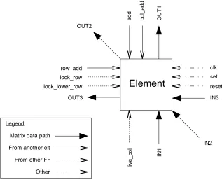
4 Main Processing Unit
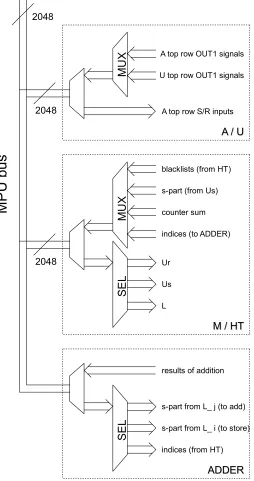
The MPU is a collection of seven chips comprising five functional units, each with its own responsibilities and behavior. We discuss each functional unit in turn: the traffic controller, the row reducer, the multiplier, the hash table, and the adder. Each functional unit is connected to a 2048-bit-wide bus called the MPU bus.
4.1 MPU Data Flow
We describe the sequence of events that will occur inside each MPU when it is agreeing, when it is extracting equations and when it is gluing. The particular details of each component are discussed in that component’s section below. Figure 5 gives an overview of how most of the components are interconnected. (The traffic controller sits on the north end of the MPU bus, directing traffic between it and other traffic controllers of other MPUs.)
The high level order of operations during an agreement between two symbols Si and Sj is as given in Figure 6, and the—somewhat similar—
procedure for gluing two symbols Si and Sj is described in Figure 7.
Finally, Figures 9 and 8 list the high level order of operations for extract-ing equations from a symbol and for a mass row reduction respectively. Subsequently we discuss the individual components of an MPU, but for the sake of readability postpone low-level details and area estimates to the appendix.
4.2 Traffic Controller
The traffic controller is a collection of four chips responsible for receiving symbol data from neighbor MPUs, storing it, and pushing it across the MPU bus if need be. After the results of various computations from other functional units are complete, the traffic controller will store or forward to a neighbor MPU those results, depending on what is currently being done. This is the only functional unit that is connected to other MPUs and the MCP, as well as the MPU bus. Details on the architecture of the traffic controller and how it operates are given in Appendix A.
4.3 Row Reducer
MP
U
b
us
M
U
X
M
U
X
S
E
L
S
E
L
A top row OUT1 signals
A top row S/R inputs U top row OUT1 signals
blacklists (from HT)
s-part (from Us)
counter sum
indices (to ADDER)
Ur
Us
L
results of addition
s-part from L_ j (to add)
s-part from L_ i (to store)
indices (from HT) A / U
A / U
M / HT
M / HT
ADDER
ADDER 2048
2048
2048
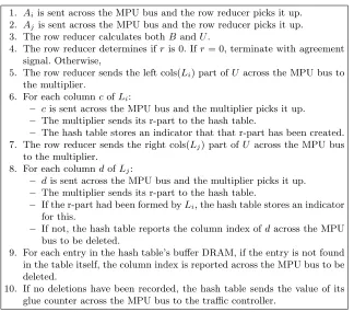
1. Aiis sent across the MPU bus and the row reducer picks it up. 2. Ajis sent across the MPU bus and the row reducer picks it up. 3. The row reducer calculates bothB andU.
4. The row reducer determines ifr is 0. Ifr= 0, terminate with agreement signal. Otherwise,
5. The row reducer sends the left cols(Li) part ofU across the MPU bus to the multiplier.
6. For each columncofLi:
– cis sent across the MPU bus and the multiplier picks it up.
– The multiplier sends its r-part to the hash table.
– The hash table stores an indicator that that r-part has been created. 7. The row reducer sends the right cols(Lj) part ofU across the MPU bus
to the multiplier. 8. For each columndofLj:
– dis sent across the MPU bus and the multiplier picks it up.
– The multiplier sends its r-part to the hash table.
– If the r-part had been formed byLi, the hash table stores an indicator for this.
– If not, the hash table reports the column index ofdacross the MPU bus to be deleted.
9. For each entry in the hash table’s buffer DRAM, if the entry is not found in the table itself, the column index is reported across the MPU bus to be deleted.
10. If no deletions have been recorded, the hash table sends the value of its glue counter across the MPU bus to the traffic controller.
Fig. 6.High level order of operations during an agreement.
area inside this chip. The row reducer has four responsibilities: compute a row-reduced version of A(i. e., the vertical concatenation of Ai and Aj
when they are received), compute the matrix U such thatU A yields the row-reduced matrix that will appear in theApart, compute the matrixV
such thatV Lis row reduced, and determine which rows ofV Acorrespond to URHS equations. During a glue, the data stored in the Apart will be
sent back across the MPU bus. (This corresponds to B in the MRHS
1. Aiis sent across the MPU bus and the row reducer picks it up. 2. Ajis sent across the MPU bus and the row reducer picks it up.
3. The row reducer calculates bothB andU, determines ifris 0, and sends
B across the MPU bus to be stored.
4. The row reducer sends the left cols(Li) part ofU across the MPU bus to the multiplier.
5. For each columncofLi:
– cis sent across the MPU bus and the multiplier picks it up.
– The multiplier sends its s-part to the adder for storage.
– Ifr6= 0, the multiplier sends its r-part to the hash table, and the hash table stores theLicolumn index that gave rise to the r-part. 6. The hash table re-examines its DRAM buffer, possibly sending pairs of
data across the MPU bus to the adder.
7. The row reducer sends the right cols(Lj) part ofU across the MPU bus to the multiplier.
8. For each columndofLj:
– dis sent across the MPU bus and the multiplier picks it up.
– The multiplier sends its s-partsto the adder for adding.
– Ifr6= 0, the multiplier sends its r-part to the hash table.
– Ifr6= 0, the hash table sends all indices fromLithat match the r-part across the MPU bus to the adder. For each such indexi,
• The s-part at indexiis looked up in the adder.
• The s-part is retrieved, added tos, and sent across the MPU bus.
– Ifr= 0, the adder runs through all its contents. For each such index
i,
• The s-part at indexiis looked up in the adder.
• The s-part is retrieved, added tos, and sent across the MPU bus.
Fig. 7.High level order of operations during gluing.
4.4 Multiplier
The multiplier occupies one part of a chip named M/HT. If the MPU is agreeing two symbols, the multiplier receives data from A/U and stores it in a processing area called Ur. If the MPU is gluing two symbols, the multiplier will also receive additional data from A/U and store it in a separate processing area called Us. It then receives the L-part of a symbol one column at a time, and multiplies it with the contents in Ur and (if gluing) Us. Once this multiplication is complete for the received L-column, the multiplier will send the result from Ur (called an r-part) to the hashtable. If gluing, it will also send the result fromUs (called an
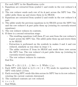
For each MPU in the Hamiltonian cycle:
1. Equations are extracted from symbol 1 and reside in the row reducer’sA part.
2. The row reducer sends each row of itsApart across the MPU bus. The adder picks them up and stores them in its SRAM.
3. Equations are extracted from symbol 2 and reside in the row reducer’sA part.
4. The adder sends the previous equations in its SRAM across the MPU bus and the row reducer’sApart picks them up (rotating its currently-stored equations).
5. The row reducer reduces its contents. 6. If there is a second extraction stage:
– The resulting equations (call themE) are sent from the row reducer’s Apart across the MPU bus. The adder picks them up and stores them in its SRAM.
– Extraction is performed on the symbols in snakes 3 and 4 and row reduced, similarly as was done in steps 1–5.
– The adder retrieves E from its SRAM and sends these rows across the MPU bus. The row reducer’sA part picks them up (rotating its currently-stored equations).
– The row reducer reduces its contents. End For.
DefineW={0,1,2,3, . . .}. Seti←2. Whilei≤q:
1. Each MPU with label in{i/2 +ki |k ∈W}sends its equations to the
MPU with labeli/2 less.
2. Each receiving MPU sends this data across its MPU bus to its row reducer, rotating the current contents downward.
3. The combined contents are row reduced. 4. i←i×2.
End While.
Fig. 8.High level order of operations during a mass row reduction.
4.5 Hash Table
The hash table is used in both PET SNAKE’s agreeing and PET SNAKE’s gluing phase, and it is designed to process one write query per clock cycle—similarly, for look-ups, one look-up query per clock cycle can be coped with. Elements to be stored or looked up in the hash table are r-parts with a (zero padded) size ofrmax= 135 bit, and the hash table is
designed to store up to 220 such r-parts. Details on the architecture and the inner working of the hash table are discussed in Appendix D.
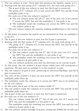
1. The row reducer is reset. (Note that this produces the identity matrix in U.) 2. Starting with the first group of 211columns of L, for each such group of L:
– TheApart of the row reducer is reset but theUpart is preserved.
– The group of 211columns of L is sent across the MPU bus andUsof the multiplier picks it up.
– For each row of the row reducer’s current U:
• The row reducer sends the left 211 bits of the next row of its current U across the MPU bus and the multiplier’s L bus picks it up.
• The multiplier sends the resulting row across the MPU bus and the row reducer picks it up.
– The row reducer reduces its contents, making modifications to the current U.
> At this point,Ucontains the matrix we are interested in. Now we multiply it to all of L:
3. TheApart of the row reducer is reset but theUpart is preserved.
4. Starting with the first group of 211columns of L, for each such group of L:
– The group of 211columns of L is sent across the MPU bus andUsof the multiplier picks it up.
– For each row of the row reducer’s U:
• The row reducer sends the left 211 bits of the next row of U across the MPU bus and the multiplier’s L bus picks it up.
• The multiplier sends the resulting row across the MPU bus and the row reducer’sApart picks it up.
– The row reducer performs zero and one detection on its currentApart.
> At this point, the row reducer’sApart knows which rows will correspond to equations. We just need to multiply U to the symbol’s A part:
5. The row reducer’sApart is reset, preserving its detection flip-flops, and theU part is preserved.
6. The rows of the symbol’s A part are sent across the MPU bus andUs of the multiplier picks them up.
7. The multiplier sends the columns of A across the MPU bus to be picked up by the row reducer.
> At this point, theApart of the row reducer holdsAT.
8. The row reducer sends the columns of A across the MPU bus andUsof the multiplier picks them up.
9. TheApart of the row reducer is reset but theUpart is preserved. 10. For each row of the row reducer’s U:
– The row reducer sends the left 211 bits of the next row of U across the MPU bus and the multiplier’s L bus picks it up.
– The multiplier sends the resulting row across the MPU bus and the row reducer’sApart picks it up.
11. The row reducer rotates through itsApart, setting the 2048th bit of each row according to its detection flip-flops.
Fig. 9.High level order of operations of extracting equations from a symbol.
being uniformly distributed, the probability that no collision occurs is
≥Q220−1
4.6 Adder
The adder is comprised of its own chip, which is largely a memory storage device. The adder is only used during gluing and equation extraction. During a glue, while the columns of Li are being processed, M/HT will
send out s-parts across the MPU bus. These will be picked up by the adder and stored in a collection of 256 DRAMs. Later, for each column in
Lj that is being processed, the adder first acquires an s-part and stores
it in a separate row of flip-flops called theadding register. Then the hash table will send across the MPU bus either a series of indices in Li that
match to that particular Lj column (i. e., whose P rij columns are the
same), or a popularity number of the resulting r-part. In the first case, the adder will look up the indices in its DRAM collection. In the second case, it will use the popularity number to find indices in its own table, and look those up in its DRAM collection. The resulting s-parts are then added to the adding register, and the sum is sent back across the MPU bus. During equation extraction, the adder will store groups of equations temporarily to be row reduced later. More details on the architecture and the internal working of the adder are given in Appendix E.
5 Performance Analysis I: Total Chip Area and Cost
With the area estimates in Appendix A–E, the size of the five functional units per MPU can be summarized as shown in Table 1.
Component Traffic Controller Row Reducer Multiplier Hash Table Adder Area in cm2 4×3.9 3.8 0.43 0.41 1.1
Table 1.Size of individual MPU components.
Thus, the total chip area of the (seven) chips comprising one MPU computes to
4·3.9
| {z }
4 chips + 3.8
|{z}
1 chip
+ 0.43 + 0.41
| {z }
1 chip
+ 1.1
|{z}
1 chip
= 21.34<22 cm2.
size requirement, but it is important to note that none of the involved chips is larger than 3.9 cm2, and the resulting device is designed to host a system of symbols as needed to attack a modern block cipher like AES-128. As far as cooling goes, the most critical part of our design appears to be the row reducer, specifically theA/Uchip. We estimate this chip to have about 2/3 of the number of transistors of an IntelR XeonR X7460, the latter being clocked at more than 2.5 times the rate of what we anticipate for PET SNAKE [10]. Further, high switching activity of A/Uis expected to occur only over short time periods, followed by a longer time where most of the chip is inactive. Overall, we do not expect cooling to pose a major obstacle.
One MPU uses some 22 cm2 of silicon. If we assume a 30 cm wafer to cost $5000, the pure silicon for one MPU calculates to about $160. If we apply a factor 4 for the full design, including the board and some safety margin, one MPU is about the price of one PC. Therefore we compare the performance of one MPU with one PC. The next section gives a simplified model to analyze the running time in a software implementation on a PC, and in Section 6.5 we present measurements when working with 4 rounds of PRESENT.
6 Performance Analysis II: PET SNAKE versus Software
To measure the time cost of an MPU versus software, the MPU’s time is measured in clock cycles. For PET SNAKE we assume a 1 GHz clocking rate: with each component of our architecture having a gate depth of four or less, we believe such a clocking rate not to be implausible. Software’s time is given in number of processor steps. Factors which relate to the software moving data in and out of memory, cache, and so forth can be captured via a constant α (i. e., each step takes α clocks on average), so a step count serves as a sort of best case scenario for software.
Suppose we are agreeing two symbolsSi and Sj. Let Ai have
dimen-sions wi ×y, Aj have dimensions wj ×y, Li have dimensions wi ×ci,
and Lj have dimensionswj×cj. Note that y then is the number of
vari-ables in the cryptosystem. Let β be the number of bits of a value that the processor can perform arithmetic on at once; in modern machines,
β ∈ {32,64}.
6.1 Linear Algebra
Let A be the vertical join of Ai and Aj. Then A has size (wi+wj)×y.
usually true in the middle and later stages of a run. Let γ be the chance a second 1 exists in a column of A provided a 1 exists already in that column. Note that γ will change from symbol to symbol, but 0≤γ ≤1.
Hardware. JONES has two advantages over software: if a zero column exists, we dispense with it in one step, and if an add is to be performed, this also takes one step. Further, the modifications to U are done in parallel toA.
Lethbe the number of columns ofAthat have more than one 1. Then
we have that γ = w h
i+wj−h, and soh =
γ
1+γ(wi+wj). Thus, the number
of columns ofAthat have exactly one 1 arewi−h+wj−h, which yields
1−γ
1+γ(wi+wj). Label this valuet. Adding h and tgives the total number
of populated columns of A. So, if we let z be the number of columns of
A which are all zero, theny−z=h+t= 1+1γ(wi+wj).
Now, since the matrices Ai and Aj are already row-reduced prior to
this process, we have some reasonable expectations on where to find a 1 if it exists in a column at all; that is, if it is not near the main diagonal ofAi, it is near the main diagonal ofAj. It could happen thath= 0 and
we are extremely unlucky with 1 placement, in which case JONES will take y+12(wi+wj)2 clocks.
This will almost never happen, however. If there are two ones in the leftmost column of A, one of them will be near or at the top. If there is only one 1, it will either be at or near the top, or it will be roughly halfway down. If there are none, we just shiftover without further examining the column. So, for the h columns, we won’t have to shift the rows of Aup, and for about 12t columns, we still won’t. For the other 12t columns, we can expect to perform shiftups equal to about half of the unlocked rows. After an add, another locked row is created, so the number of unlocked rows is lessened. Further, we can expect at least two such adds to be per-formed between times we have to shiftup half of the unlocked rows. Hence, the first time we encounter such a column we shiftup 12(wi+wj) rows, but
the next time we encounter such a column we will shiftup 12(wi+wj−2) =
1
2(wi+wj)−1 rows. Hence, we have a truncated triangular sum of shiftups to count. Since the number of unlocked rows starts at wi+wj, we
ex-pect a total shiftup count of 12(12(wi+wj))2−12
1
2(wi+wj)− 1 2t
2
, which yields 181−(γ4+1)γ22
(wi +wj) shiftups. Hence, our total clock count is
y+ 181−(γ4+1)γ22
(wi+wj) =y+18(1
−γ)(1+3γ)
Software. Different choices for the algorithm can be made, and here we consider a situation where Gauß elimination is used to perform the row reduction. For the matrix sizes at hand, this seems a plausible option. Then software must examinewi+wj elements in the first column. It first
must find a 1, and if successful, it scans the rest of the column looking to add a row. If it finds such a row (i. e., with a 1 in this column), it performs an add of the two rows which takesy/β steps.
It then proceeds to the next column, examining the bottommostwi+
wj−1 elements, and addition of rows costs (y−1)/β steps. And so on.
We note that any additions that are performed in A are also performed in the U that is being built, andU has dimensions (wi+wj)×(wi+wj),
though we do not explicitly count them.
If y ≥ wi +wj, then in total there are 21(wi + wj)2 locations to
visit, with a truncated triangular sum of addition steps in A equal to
γ β
1
2y 2−1
2(y−(wi+wj)) 2
= βγ(wi+wj)(y−12(wi+wj)). In these cases
we expect γ to be closer to 0 than to 1, and so hardware offers at least a factor 4 improvement in clocks over steps.
Ify≤wi+wj, then we have a truncated triangular sum of locations to
visit equal to 12(wi+wj)2−12(wi+wj−y)2 =y(wi+wj−12y). The addition
steps total γβ12y2. In these cases we expect γ to be closer to 1 than to 0, and we expect few, if any, zero columns. Hence we use y= 1+1γ(wi+wj),
and putting just the locations expression over the clocks expression, we have a factor improvement equal to
1
1+γ(wi+wj)
(wi+wj)−121+1γ(wi+wj)
1
1+γ(wi+wj) +
1 8
(1−γ)(1+3γ)
(1+γ)2 (wi+wj)2
=
1+2γ
2+2γ(wi+wj)
1 8
(1−γ)(1+3γ)
1+γ (wi+wj) + 1
As γ increases towards 1, this expression will tend towards a factor 3
4(wi+wj) improvement (i. e. JONES takes linear time). This does not come as a surprise, for whenγ gets closer to 1, there is less and less need to perform shiftups to find 1s.
6.2 Matrix Multiplication and Recording Deletions
Hardware. OnceUrandUsare loaded, their multiplications toLi occur
in parallel; similarly forLj. Because of the pipeline structure of the
mul-tiplier, all the columns ofU Tij (similarly,U Tji) are computed at a rate of
Hence, processingLitakesciclocks, plus a few clocks of latency. Then,
processing Lj also takes cj clocks, plus a few clocks of latency. Since the
MPU bus must be used to report a deletion, it will take one clock per deletion, up to a maximum of cj clocks to report all of Lj’s deletions.
Finally, Li is processed again from the hash table’s DRAM buffer, and
those entries are looked up (for deletions) at the same rate. Since the hash table can report a deletion at the same time as looking up the next value, we count ci clocks to report any deletions forLi.
Since the traffic controller can record a deletion in a pipeline fashion and send a column at the same time, no additional overhead is counted for this. Finally, because of the ‘just in time’ nature of symbol transmission, it takes no additional time for a deletion to actually take hold in a symbol. Thus, two symbols will have their deletions processed in 2ci + 2cj
clocks, plus some small latency. (At the very end of an agreement phase, an additionalciclocks will also be spent for one symbol. This is a one-time
latency cost.)
Software. Using a Method of Four Russians (cf. [1]) approach in software is certainly helpful in constructing P rij. The T-storage matrix is set up
on each pass. Arranging the data the same way the hardware handles it, this T matrix has 2krows ofrentries each, wherekis the storage constant (typically k = 8, but can be increased), and r = rows(A)−rank(A). It is built in 2k rβ steps. Then, for (the givenk bits of) eachLi column, the
appropriate entry in the T matrix is read off and stored (taking βr steps), waiting to be added later. This continues for the entire pass. Hence, a pass takes 2k rβ +cirβ steps. Afterwards, a new T matrix will need to be
built. Since there are wi
k passes, all passes total comprise
wi
k(2
k +c
i)βr
steps.
After all passes are complete, the subresults are added together to produce the final result of the multiplication. We can use logwi
k additions
of matrices, each addition takingciβr steps. This gives a total step count
of
wi
k(2
k+c
i)
r β +ci
r βlog
wi
k = r β
wi
k 2
k+c
i(
wi
k + log wi
k )
to constructP rij. A similar expression will result when constructingP rji.
One could try to optimize by increasingk to 16 or so, but k = 32 is troublesome as the 2k term starts to dominate.
The situation gets worse for software; it still has to search through the data to find matching r-parts. Sorting P rij will take at leastcilogci
Similar expressions result when sorting P rji. Finally, a bilinear search
taking βr(ci+cj) more steps must be performed to find matching r-parts.
Once the mismatches are found, columns have to be deleted fromLi and
Lj; this takes βr(ci+cj) steps. Hence, total sorting and searching for both
matrices takes βr (ci(2 + logci) +cj(2 + logcj)) steps.
In total, we have
r β
wi+wj
k 2
k+c
i(
wi
k + 2 + logci wi
k ) +cj( wj
k + 2 + logcj wj
k )
steps to agree the symbols Si and Sj.
The MPU has a very clear and obvious advantage. Aside from the additional terms the software induces in its step count, it is important to stress that the hardware does not rely on the values ofr,wi, orwj at all.
Hence, larger (whose maximum value is 211) will dramatically slow down the software, but the hardware will be unaffected. Since r will steadily increase over the entire run, hardware’s advantage will grow over time.
6.3 Gluing
Both hardware and software must pay the linear algebra times and the multiplication times as described earlier. From there the situation changes slightly. At this point we know that we may only construct a symbol whose L-part has no more than 220 columns, so we label the number of such columns d.
Hardware. During the matrix multiplication of Li, r-parts are being
stored in the hash table at the same time, so we do not count this cost again. However, s-parts are being sent to the adder at the same time, so the adder’s DRAM collection is filled for free.
Afterwards, the hash table will go through a preprocessing of its ci
entries. It may happen that these values hit the SRAM of the adder entirely too quickly, at which point we must pay upwards of an 8-clock penalty per such index. In the worst case this takes 8ci clocks in total,
but is expected to average to more like 2ci over the course of an entire
run.
Then, Lj is processed. We get an s-part in one clock (after some
128 bits at a time (that is, 6 indices per 8 clocks), the penalty of multiple fast read requests is mitigated.
Hence, we have worst case behavior of 8ci+ 86dand best case behavior
of ci+dclocks to finish all additions.
Software. It is plain that the software will suffer tremendously if it has to re-match r-parts to find corresponding s-parts to add, so we give it a fighting chance by allowing it to store the matching indices during agree-ment. (This gets expensive in memory with a state of several hundred symbols, but can nonetheless be theorized.)
Then it merely performs lookups of its storage data. Since there ared
pairs of s-parts to be added, software takes rβdsteps to finish all additions. Again, asr steadily increases over a run, software becomes vastly inferior to hardware, which does not rely on the value of r.
6.4 Equation Extraction
We begin by analyzing the time taken by extracting equations from a particular symbol withAof dimensions w×y andLof dimensionsw×c. We suppose Ahas the same bias of data as described in Section 6.1, but
Lis not guaranteed to have any bias of data. We calculate supposing that
L’s 0s and 1s are uniformly distributed.
Hardware. We follow Figure 9. In step 1, the row reducer is reset, taking 4096 clocks to bring Uback to the identity matrix. Then we havedc/211e
groups of columns ofLto process to find U such thatU Lis row reduced. For each of these groups, we first send the 211 columns toUs, taking 211 clocks, followed by sending the top 211 rows of the row reducer’sUpart, each producing a row that the A part must store. Each row takes two clocks (one to read, one to write, as data must go back and forth across the MPU bus). So, to get a temporary result of a multiplication in A, we require 212 clocks. To rotateUback into position, we require another 211 clocks.
Step 3 takes at most 212 clocks, since we just need to reset A. In step 4, we again have dc/211e groups of columns of L to process. For each group, we first send it to Us taking 211 clocks. Then the multiplication happens once more, taking 212 clocks, with the temporary result in A. Then zero and one detection commence, requiring A to cyclically shift upwards completely, taking 212 clocks. In the first 211 of these, the ZD column is populated, and the OD row gets set to the sum of all rows in A. Then in the second 211clocks, the OD row cyclically shifts left, setting the OD flag. Hence, step 4 takesdc/211e(211+ 212+ 212), which is at most 5c clocks.
Step 5 is similar to step 3, taking 212 clocks. Step 6 takesw clocks to populateUs. Step 7 takes at most 212clocks (one to multiply, one to send) to send the columns ofAback toA. Step 8 takes 211clocks to repopulate Us. Step 9 is similar to step 5, taking 212clocks. Step 10 will require 212 clocks (one to send, one to receive the multiplication, for each row inU). Step 11 will require 212 clocks to set the 2048th element according to its detection flip-flops, followed by another 212clocks to put the (potentially) nonhomogeneous equation at the top.
Hence, to extract the equations from a symbol, PET SNAKE uses at most 212+ 211+ 8c+ 212+ 5c+ 212+w+ 212+ 211+ 212+ 212+ 212+ 212= 18(211) + 13c+w≤13,670,400 clocks.
Software. We once again consider Gauß elimination for the row reduc-tion. In almost all caseswc, and since each entry ofLis equally likely to have a 0 or a 1, we note it will take one or two steps to find a pivot row for row i. However, once a pivot row is found, it will have to be added to about half the remaining rows, and each such addition will take c−βi steps. Hence, the step count is
w
X
i=1
w−i
2
c−i β =
w
4β
cw−1
3w
2−c+1 3
which is easily dominated by the cw4β2 term. As the run continues, w
approaches y, and c almost always remains at 220. Taking an average value of w to be 210 and β = 32, this term becomes 233.
Once L is row reduced, we must take the corresponding U (of size
w
k matrices to be added. We can structure things to take log w
k additions,
each addition costing wyβ steps, for a total of
wy β
1
k(2
k+w) + logw
k
steps for the entire multiplication. However, using the same values as above (with y= 211and k= 8), this reduces to approximately 223 steps. We see that the cost in software is about a factor of 1000 in steps over clocks for the equation extraction in the common case.
Assigning the final 0/1 column to construct the equations is trivial in both settings. Software provides no benefit over hardware when bring-ing all the equations together to be row reduced, so we do not perform an analysis of this. Finally, reducing with the current equation set to determine consistency is also trivial in both settings.
6.5 Software Measurement
It should be noted that, in the above derivations, the linear algebra is al-most always dominated by matrix multiplication and recording deletions, both in hardware and in software.
In order to get a handle on performance metrics, four rounds of PRESENT were cryptanalyzed in software (k= 8,y= 308) using MRHS with the above options, and this entire session’s timing values were re-corded. The platform was an Intel E2180 processor, β = 32, on a single core of 2 GHz, with 2 GByte of RAM. Out of the nearly 10,000 agreements that took place, the vast majority took less than two seconds. We removed these from consideration since fractions of seconds were not measured. Many calculations were made on the remaining 350 or so agreements us-ing the above step count formulas, some results of which are illustrated in Table 2. We see no problem using just these∼350 values since in a full cryptosystem operated on by PET SNAKE, there will commonly be high
wi, wj,r, ci, and cj values, and these data points are more reflective of
this scenario. It should be noted that we calculated steps using γ = 0.5; varyingγ in either direction does not adversely affect our overall results. An average of the ∼350 time improvement factors gives an average improvement of 2,281 for four rounds of PRESENT. As noted above, as
included in the step count, such as loop counter variables incrementing, allocation space instructions, and low-level memory management.
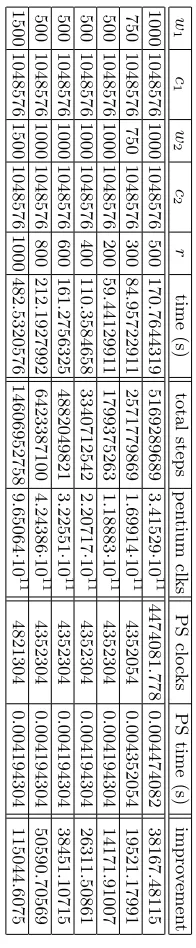
Once we have a good handle on theαthat a given processor exhibits, we can predict software behavior for larger systems. For example, if PET SNAKE runs an MRHS attack on AES-128 or more rounds of PRESENT, it won’t be uncommon for y >1500, wi >1024, and r >1024. Modeling
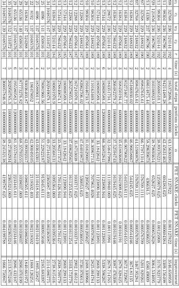
such systems in software directly is problematic owing to the lack of sufficient on-board memory at the time of this writing, but we can predict step counts for software under these conditions. Table 3 gives the relevant predictions fixing α = 66.068. In the later stages of a given attack of a full cipher of something like AES-128,we’ll see symbol sizes listed in this table. The relative improvement of PET SNAKE is now even clearer, touching a six-digit improvement.
Finally, it is worth noting that other software methods may be used to multiply large matrices; it is certainly possible that some of them may be more efficient than the Method of Four Russians, and so the improvement factor may be reduced. However, PET SNAKE’s time is still unaffected by these large symbols, processing each pair in less than half of a hundredth of a second. We feel that such absolute speed is too compelling to be dismissed.
7 Performance Analysis III: Parallelization
Guessing Variables. PET SNAKE will, in its depth-first search of keys, eventually guess enough keys so that either the system is found to be inconsistent or the key is correct. This number of keys we refer to as δ. So that it may make appropriate use of parallelism, PET SNAKE will eventually guess enough keys discovering δ, and then make note of its available storage. Then the MCP will be able to determine how high in the guess tree it can fork a new guess into another area of the board, while having the ability to store the states required for a sub-branch of this new guess as well as for the original branch. The idea here is that PET SNAKE will use all of its MPUs to finish off a branch of a guess tree as quickly as possible. If more MPUs become available, more guesses can potentially be forked.
be re-performed in one series of agrees and glues, increasing the overall running time, but PET SNAKE at least has recovery options should stor-age requirements vary wildly across parallel branches of the guess tree. For this reason, PET SNAKE will never delete the highest state in the guess tree, that is, the state which was arrived at before any guesses were committed.
Using Multiple PCs. To cope with a cipher like AES-128, the only plausible option seems to use a cluster of PCs, but here the communi-cation cost between these PCs will add another significant factor to the overall running time of the algorithm. Connecting networked PCs in the same way as PET SNAKE connects its MPUs will introduce additional time spent: suppose that a grid of PCs is connected so each can talk to its neighbor in each cardinal direction using gigabit Ethernet, and suppose that this network actually communicates perfectly (i. e., 1 gigabit/sec). PET SNAKE’s connections are 1024 wires clocked at 1 GHz, so it can transmit 1000 gigabit/sec between MPUs. This makes the PC network 1000 times as slow. With the observation that a PC agrees1000 times slower than an MPU, the PCs could also implement a ‘just in time’ de-livery method to reduce agreement communication times. However, when symbols need to be moved between agreement stages or to prepare for a glue, we see that the movement time for a PC is a little over 2.15 sec per symbol per hop (over 4.5 minutes per agreement phase, assuming no deletions), whereas for PET SNAKE it is 0.00215 sec per symbol per hop. Hence, a faster network between PCs will need to be established, which in turn adds to the cost of such a solution.
Finally, for multiple PCs to provide the same storage as PET SNAKE, a single PC has to store 4680 MB, not including active memory of at least 325 MB. This is slightly larger than 4 GB per PC, and so more expensive motherboards that can provide larger memory will need to be acquired. (Slower storage solutions like hard drives can be used instead, but given their notorious relative slowness, the times for loading and storing would start to dominate an overall time estimate, and this would make finding a key infeasible.)
8 Conclusion