Image Encryption by Pixel Property Separation
Karthik Chandrashekar Iyer and Aravinda Subramanya
Abstract— Pixels in an image are essentially constituted of two properties, position and colour. Pixel Property Separation, a radically different approach for Symmetric-key image encryption, separates these properties to disturb the semantics of the image. The scheme operates in two orthogonal stages each requiring an encryption key. The first stage creates the Position Vector, an ordered set of Pixel Position Information controlled by a set of plaintext dependent Random Permutations. A bitmap flagging the presence of all the 24 bit colours is generated. The second stage randomly positions the image width and height within the ciphertext and finally applies a byte transposition on the ciphertext bytes. The complete set of image properties including width, height and pixel position-colour correlation are obscured, resulting in a practically unbreakable encryption. The orthogonality of the stages acts as an anti-catalyst for cryptanalysis. The information retrieved from compromising a stage is totally independent and cannot be used to derive the other. Classical cryptanalytic techniques demand huge number of attempts, most failing to generate valid encryption information. Plaintext attacks are rendered ineffective due to the dependency of the Random Permutations on the plaintext. Linear and Differential cryptanalysis are highly inefficient due to high Diffusion and Confusion. Although the paper describes the algorithm as applied to images, its applicability is not limited to images only. The cryptographic strength is independent of the nature of the plaintext.
Index Terms— Pixel Property Separation, Image Encryption, Cryptanalytic Error Avalanche Effect, random colour permutation, security, cryptography, pixel position, pixel colour, plaintext attack, confusion, diffusion.
1 INTRODUCTION
I
MAGE and data security is a major challenge in Storage and Transmission applications. Encryption algorithms for these applications are exposed to various threats and security breaches due to the availability of immensely powerful and inexpensive computational resources. Brute Force and Statistical attacks on the existing cryptographic algorithms is not only possible, but are becoming more practical in the wake of technological advancements like Distributed and Grid Computing. Vast amounts of data can be processed in parallel by agents distributed over the Internet and aid in revealing secure information. Several data encryption algorithms like DES [1], AES[1], IDEA[1] are being employed for protecting digital information, chaos based [5][17], combinatorial permutation [13] and optical techniques [12] are also proposed for encrypting images. Along with these developments in the security domain, the vulnerability of the algorithms are also being exposed. It is possible to build a machine that can determine the key used for DES encryption at a cost as low as US $10000 [16]. It is also vulnerable to Linear and Differential cryptanalysis or a combination of both. Techniques like theSide Channel Attackand several Cache Timing Attacks have been developed to compromise AES algorithm and retrieve the encryption key in as less as 65ms with 800 write operations [6]. Chaos based techniques like theCKBAare prone to plaintext attacks [7] and algorithms using combinatorial permutations are as strong as the permutation of the least sized block even if they apply multiple permutations over different sized image blocks.Applications in the Automobile, Medical, Construction and the Fashion industry require designs, scanned data, building plans and blue-prints to be safe-guarded against espionage. Considering the long lifetime of images in the mentioned domains, it is imperative to develop and employ techniques which protect the content throughout their lifetime.
A novel image encryption technique based on Pixel Property Separation is proposed in this paper. The pixel position and the colour are separated and encoded using a set of Random Permutations. The algorithm conceals the image colour-position correlation, the colour information and the image size. The concealment of the image size considerably enhances the cryptanalytic complexity. The Ciphertext only attack is practically impossible while the plaintext and the differential attacks fail to reveal useful encryption information. The algorithm is robust against Plaintext attacks due to the utilization of Plain-text Dependent Random Permutations ([18],[19]) to separate pixel properties. The time required for a successful Brute Force Attack is huge attributing to the high key lengths and orthogonality of encryption stages. Hence it is not likely to be broken by brute force methods using any existing technology.
• K. C. Iyer and A. Subramanya are with the DSP Software Centre, Innovation Center, Business Unit Home, NXP Semiconductors (formerly Philips Semiconductors), Bangalore - 560 045, India.
The organization of the paper is as follows. Section 2 describes Pixel Property Separation, section 3 explicates and illustrates the encryption scheme. Section 4 and 5 discuss in detail the various cryptanalytic attacks and the encryption strength. The last section presents the simulation results. A mathematical model for the encryption algorithm has been presented in the appendix.
2 PIXELPROPERTY SEPARATION
Pixels in an image are essentially constituted of two properties, pixel position and pixel colour. The pixel position is defined by the (x, y) co-ordinates indicating the horizontal and vertical distance of the pixel from (0,0)and the colour value can be a RGB colour or a greyscale value.Pixel Property Separation is an encoding technique that separates the pixel position and colour and represents them as distinct vectors. The separation process results in two ordered vectors, the Position Vector P os representing the pixel positions and the Colour Bitmap Vector CBM that represents the colours. The vectors are defined as follows.
1) The Position VectorP osis an ordered set of pixel co-ordinate positions. This vector bears a position entry for each pixel in the input image. For each(x, y) position entry, theP os vector also indicates by a flag f lg whether an entry is the last entry for that colour. A flag value of 1 indicates that the entry is the last for that colour, a value of 0, otherwise.
2) The Colour Bitmap CBM is an ordered set of bits(flags) that indicate the presence of a colour C
in the input image. The number of bits in CBM is equal to the number of colours in the colour system used by the image. For example, if the image uses a 24 bit RGB colour system, then the
CBM would be composed of 224 flags indicating the presence of the 224 RGB values. A flag value of 1 indicates the presence of a colour and a value 0, otherwise.
These two vectors in combination, completely represent the image. The following illustration describes the technique.
Consider a systemSof 6 coloursC0 throughC5,S={C0, C1, C2, C3, C4, C5}. Letimgbe a colour image with width W = 3 and height H = 3 and be composed of a set of 4 colours, {C0, C1, C2, C4}. Figure 1 depicts the image img. For a better understanding of the technique, we represent the input image img
as depicted in Figure 1b where pixels are grouped based on their colour. The input image is initially scanned to group pixels based on their colour. The Position Vector P os is created as follows. For each
Fig. 1: Input image representation a. Original b. Colour based pixel grouping
colour C ∈S, starting from C0 to C5, the (x, y) positions of the pixels bearing C is augmented to P os. Flag f lg is also entered for each pixel considered. For example, there are 4 pixels bearing the colourC0. The position of the first pixel bearing C0 is (0,0) and it is not the last pixel bearing C0. Hence the first entry in P os is {(0,0),0}. Considering the second and third pixels bearing C0, the next two entries in
P os are{(2,1),0} and{(0,2),0}. Pixel (1,2)is the last pixel bearing colour C0. Hence theP os entry for that pixel is{(1,2),1}. Hence, for the colour C0, P os=[{(0,0),0},{(2,1),0},{(0,2),0},{(1,2),1}]. Similarly,
1) Considering C1,P os=[{(0,0),0},{(2,1),0},{(0,2),0},{(1,2),1},{(2,0),1}]
2) Considering C2,P os=[{(0,0),0},{(2,1),0},{(0,2),0},{(1,2),1},{(2,0),1},{(0,1),0},{(1,1),0},{(2,2),1}] 3) Considering C3.Since there are no pixels inimgbearingC3, no entries are made forC3.
4) Considering C4,P os=[{(0,0),0},{(2,1),0},{(0,2),0},{(1,2),1},{(2,0),1},{(0,1),0},{(1,1),0},{(2,2),1},{(1,0),1}] 5) Considering C5.Since there are no pixels inimgbearingC5, no entries are made forC5.
The Position vectorP os for the image imgis
P os=[{(0,0),0},{(2,1),0},{(0,2),0},{(1,2),1},{(2,0),1},{(0,1),0},{(1,1),0},{(2,2),1},{(1,0),1}]
C3 and hence theCBM entry forC3 is a ’0’. Similarly, theCBM entries corresponding to C4 andC5 are ’1’ and ’0’. Hence, CBM =[1,1,1,0,1,0]
It can be noted that the vectors P os and CBM together, completely represent the input image img. This can be shown by reconstructingimg using onlyP os and CBM. The decoding process is described below.
The first entry of CBM is a ’1’ and hence colour C0 is present in img. Since the same colour order
C0 throughC5 is used to create bothP osand CBM, the first entry{(0,0),0} in P os corresponds toC0. Hence, the pixel with position (0,0) bears colour C0. Hence, img(0,0) = C0. Since, the first P os entry bears af lg value of ’0’, it is not the last pixel bearing C0. Hence, the pixel corresponding to the second entry{(2,1),0}in P osalso bears colour C0, img(2,1)= C0. Similarly, corresponding to the third and the fourth entry inP os,img(0,2)=C0 and img(1,2)= C0. But thef lgvalue of the fourth entry in P os is ’1’ meaning that there are no more pixels bearing colour C0. For the fifth entry in P os, the next colour in
CBM is considered. The second entry inCBM corresponds to colourC1 and has a value ’1’. Hence, for the the fifth entry inP os, colour C1 is considered. Similarly, img(2,0)= C1,img(0,1) =C2, img(1,1)=
C2, img(2,2) = C2 and img(1,0)= C4.
It can be noted that the pixel position information and the colour information are completely separated and have been encoded as two distinct ordered vectors. Though it is straight forward to reconstruct the input image using P os and CBM, the advantage of such a representation of images ( or any form of digital data ) is as follows:
1) The P os vector is composed of numbers from 0 to W and 0 to H. This information is obvious if the image width and height is known.
2) no information regarding the colours is revealed. CBM encodes the colours as a bit sequence 3) the Pixel Position-Colour correlation that defines the semantics of an image, is completely disturbed.
Digital Representation of P os and CBM: Each entry in the P os vector is composed of three elements.
The ’x’ and the ’y’ co-ordinates of the pixel considered and the flag f lg indicating if the pixel is the last entry for that colour. Since the flag f lg can take only two values ’0’ or ’1’, one digital memory bit is sufficient to represent it. The value of the ’x’ co-ordinate defines the relative horizontal distance of a pixel from the origin (0,0)and can not exceed the image widthW. Hence the number of bits necessary to represent the ’x’ co-ordinate of any pixel is given bybw.
bw = If (W ≤2), then 1, else, (dlog2(W)e) bits
Similarly, the number of bits necessary to represent the ’y’ co-ordinate of any pixel is given bybh.
bh = If(H≤2), then 1, else, (dlog2(H)e) bits
Hence, the number of bits used to represent an entry in theP os vector is(bw+bh+ 1)bits. Considering all the W ×H entries in the P os vector, the number of bytes required to represent the P os vector is
Size(P os) = d((bw+bh+ 1)×(W ×H))/8e bytes
For the image img, bw=bh = 2. Hence, each entry in P os vector is represented using 5 bits and the entire vector is represented using 45 bits. The P os vector can be represented as:
P os =[(00000),(10010),(00100),(01101),(10001),(00010),(01010),(10101),(01001)]
Finally, the P os vector is represented as an ordered set of integers by packing 8 bits in sequence. For example, the first integer with value ’4’ is formed by packing 5 bits of the first P os entry and 3 bits of the second entry. The second integer with value ’136’ is formed by packing 2 bits from the second P os
entry, 5 from the third and one bit from the fourth P osentry. Similarly, the encoding continues until the last bit in P os. Since the P os vector is composed of 45 bits, the last 5 bits (last P os entry) are padded with three ’0’ bits. The final representation of the P os vector is given by P os=[4,136,216,137,85,72].
This section has clearly described the concept of Pixel Property Separation and the representation of images using the vectors P os and CBM. The next section develops the encryption algorithm based on this technique.
3 ENCRYPTION BYPIXEL PROPERTY SEPARATION
The Encryption scheme is a Secret Key Algorithmrequiring 2 keys . It operates on the input plain image
img with width W and height H, the two encryption keys key1 and key2 and generates the encrypted image img0 with width W0 and height H0 (representing the ciphertext as img0 with W0 ×H0 pixels is optional, the ciphertext can be represented as a byte sequence). The input plain image uses a colour system S composed of s colours, the number of distinct colours in img being ≤ s. For a 24 bit RGB colour space, S is the set of all colour values from 0 to 224−1 and s = 224. The scheme uses the encryption keys to generate a set of Random Permutation RPs to separately encode the pixel position and colour. The composition of the RP s cannot be determined by the keys alone. This is because, the generation of a permutation in any iteration not only depends on the key, but also depends on the results of the previous iteration. Hence, the RPs used in this encryption scheme depend both on the key and the plaintext. This renders the technique robust against Plaintext Attacks.
Encryption by Pixel Property Separation (EA) is completely based on the technique of separating pixel position and colour. To achieve better encryption strength, the basic design (BD) of separating pixel properties, explained in the previous section has been modified. The following enlists the modifications. 1) EAusesN RP number ofRPs(RP1, RP2, . . . , RPN RP)to create theP osvector whileBDused only
one permutation with colour order[C0, C1...Cs]
2) EA uses one of the s! (224! for 24 bit RGB colours) random colour permutations composed of all the colours in S as its first permutation. This is used as the first permutation RP1 in the creation of theP os vector and is also used to create the CBM. BD uses a known colour order[C0, C1...Cs]
which is not randomly picked.
3) For any colour C ∈S considered for processing in an RP, EA places exactly one pixel’s position (x, y) in theP os vector, while BD placed the positions of all the pixels bearing colourC
At any stage in the encryption scheme, theRPs are used to define a random colour order. The number of elements in the first permutationRP1 is equal to that of the setS.RP1 needs to consider all the colours inS as it is also used to generate the vectorCBM. RP1 defines a random colour order for all the colours in S. The size and the composition of the remaining (N RP −1) RPs, RP2 through RPN RP, depend on
the number of colours available for processing at the point of generation of the RP. In the illustration of Section 2, the colour order [C0, C1, C2, C3, C4, C5] can be regarded as RP1 and it defines an order for all the colours C0 through C5. Hence, the size of RP1 is 6. Applying modification 3 to this illustration would result in the consideration of one pixel each of colours C0, C1, C2 and C4 in the first iteration using RP1. It can be noted that the order of colours considered is same as that in RP1. For the second iteration, coloursC1,C3,C4, andC5 can be discarded as there are no pixels bearing these colours. Hence for RP2, there remain only two coloursC0 andC2 that need an order. RP2 would then be composed of two elements. After the second iteration, there remain three pixels for processing, bearing two distinct colours C0 andC2. Hence, the number of elements in RP3 is 2.
It can be noted that eachRP defines a colour order for the pixels considered for processing. However, after the third iteration, there remains only one pixel at position (1,2) bearing C0. Since there is only one colour available for processing, there cannot be a colour order defined. Hence, for the image img
in Figure 1, three permutations RP1, RP2 and RP3 suffice to create the P os vector. Hence, the value of
N RP forimgis 3. The valueN RP (Number of Random Permutations) makes sure that there are enough
RP s available to define a colour order for pixels, processed at the rate of ’one pixel per colour per RP’, until there are pixels to be processed in the plaintext bearing at least two colours. The key key1 is used to generate the N RP permutations RP1 to RPN RP. The derivation of N RP for an image can be found
in the Appendix.
It can be noted that the value ofN RP, the number of elements and the composition of the permutations
RP2 through RPN RP depends on the number of colours available for processing at any point in the
encryption process. This in turn depends on the number of pixels bearing each colour C ∈ S in the plaintext. Hence, the size and the composition of the random permutations used to create theP os vector depends on both the key1 and the plaintext. This greatly increases the cryptanalytic complexity and renders the technique robust against Plaintext Attacks.
The vector CBM is created using the first permutation RP1, coded and digitally represented as described in the previous section. The ciphertext is formed by concatenating the P os and the CBM
If the ciphertext needs to be represented as an image img’, the ciphertext bytes needs to be padded to render img’ as a rectangular image with integral values for W0 and H0 and with each pixel composed of 3 bytes (considering 224 colours). The values for the padding bytes needs to be randomly chosen and should not follow any pattern. The padding bytes are augmented to the ciphertext bytes before applying the final shuffle. VectorP =[P0, P1, . . . , Pp−1] gives the padding bytes wherepis the number of padding bytes necessary. It shall be noted that this is an optional step and hence need not be carried out by an implementation. The determination of the number and the values for the padding bytes is not discussed in this paper.
From the previous section, it can be noted that each entry in theP osvector can be digitally represented using (bw+bh+ 1)bits. To correctly decode such a bit-packed P os vector, the knowledge of bw and bh
is necessary. Without these values, it is not possible to discern how many bits are to be considered for the ’x’ and the ’y’ co-ordinate entries. Hence, the image width W and the height H values need to encoded as part of the ciphertext. The cryptanalytic complexity can be greatly increased if these values are randomly placed within the ciphertext. Since the values of W andH is not known, the cryptanalyst needs to attempt decryption considering all possible combination ofbwandbh values to decode theP os
vector. Section 4.2 derives an equation for the number of ciphertext byte combinations that need to be extracted from the ciphertext to list all possible candidates forW andH. Assuming a maximum value of 65535 forW andH, the encryption technique uses two bytes each(W1, W2) and(H1, H2)to representW andH respectively, with W1, H1 being the lower andW2,H2, the higher bytes. The technique randomly places the four size bytes in the ciphertext after padding. It can be noted that the technique is not limited to using two bytes to represent W and H. The following example illustrates the encryption technique.
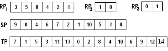
Fig. 2: Plaintext Dependent Random Permutations
The example depicted in Figure 1 has been used to illustrate the technique. Figure 2 depicts the random permutations used to encrypt img. For img, bw=bh= 2, N RP = 3, W1=H1 = 0 and W2 =H2= 3.
The first entry in RP1 is ’3’. But from the colour vector CV (Figure 1), it can be noted that no pixel bearsC3. Hence, there are noP os entries corresponding toC3. Since no pixels bearC5, there are noP os entries corresponding to the second entry ’5’. The third entry inRP1 corresponds to colourC0 and hence the first entry in P os is{(0,0),0}. Similarly, theP os entries corresponding to colours C4, C2 and C1 (in that order) are {(1,0),1}, {(0,1),1} and {(2,0),1}. Let noc represent the number of distinct colours in
img (noc = 4 in this example). It can be noted that in this technique, RP1 processes exactly noc pixels. For RP2, only C0 and C2 remain for processing. The first entry in RP2 is ’1’, which picks the second available colour for processing in CV, which is C2. Hence, the fifth entry inP os is {(1,1),0}. Similarly, after processing all pixels, the P os vector corresponding to img and the permutation set in Figure 2 is given by
P os=[{(0,0),0},{(1,0),1},{(0,1),1},{(2,0),1},{(1,1),0},{(2,1),0},{(0,2),0},{(2,2),1},{(1,2),1}]=[2,71,21,72,149,104]
Vector CBM is created using the colour order defined by RP1. CBM=[0,0,1,1,1,1]=[0,2,4].
P os and CBM are concatenated to form the vectorP B with pb elements.
P B=[P os, CBM]=[2,71,21,72,149,104,0,2,4],pb= 9
As mentioned earlier, the valuesW1,H1,W2 andH2 need to be placed at random positions within the ciphertext. But the size of the ciphertext after placing these bytes would be pb+ 4 = 13, which is not a multiple of 3.P B needs to be padded with two bytesP0 andP1 to make the ciphertext size equal to 15. Let P0 = 157 and P1 = 43.
P B0=[P B, P0, P1]=[2,71,21,72,149,104,0,2,4,157,43]
To determine the random positions for the 4 size bytes within P B0, the keykey2is used to generate a Random PermutationSP composed of(pb+p) numbers (11 in this example) with values ranging from 0 to(pb+p−1). The first four entries ofSP are used as byte positions to placeW1,H1,W2 andH2 within
F0=[H1,2,71,21, W2,72, H2,149,104,0,2,4, W1,157,43]=[0,2,71,21,3,72,3,149,104,0,2,4,0,157,43],f = 15
Finally, the vectorF0 is transposed using a random permutationT P withf elements with values ranging from 0 to (f −1). Keykey2 is used to generate T P.
F =T P(F0)=
F0, F1, . . . , Ff−1
=[149,2,72,21,4,157,0,71,104,3,2,3,0,0,43]
The ciphertext size is f = 15 bytes and is composed of nop = (f /3) = 5 pixels. Starting from the set [F0, F1, F2], each set of 3 bytes in sequence represents a pixel. The values W0 andH0 are any two factors of nop such that W0×H0 =nop. Assuming W0 = 5 and H0 = 1, the cipher imageimg0 is given by,
9765448 1377437 18280 197123 43
4 CRYPTANALYSIS
This section explicates the different techniques for cryptanalysis. The Brute Force and the Plaintext attacks have been analysed. Differential Cryptanalysis has been discussed as part of Section 5.
4.1 Brute Force Attack
In a Brute Force Attack, the algorithm implementation is considered as a black box and all valid key combinations are attempted until the correct key is discovered. The complexity of such an attack depends on the size of the keys used for encryption.
Key Size key1: The maximum size of key1, N BK1, for a given plain image depends on the value
of N RP and the number of elements in each of the N RP permutations. The first permutation RP1 is composed of224 numbers that can be arranged in 224!
ways. Ifnoci represents the number of colours
available for processing for permutation RPi, then for a given plain image, the maximum number of
key bits inkey1 isN BK1 =log2
224!
×(dnoc2!e)×(dnoc3!e)×. . . ,(dnocN RP!e)
. However, an implementation can choose N BK1 independent of the plaintext. The permutation generator generates one of the 2N BK1 possible combinations of N RP permutations.
Key Size key2: Keykey2 is used to generateSP andT P. Likekey1, the size ofkey2, N BK2, depends on the ciphertext size (f =W0×H0×3), which is a variable entity. But, the size of key2 can be chosen independent of the ciphertext size, because, though the value of (f) is plaintext/ciphertext dependent, the Random Permutation Generator generates one of the 2N BK2 random permutations of composed of
(f) numbers.
In the proposed scheme, it is not possible to individually determine key1 or key2 during decryption. This is because the correctness of the decryption attempts involvingkey1or key2cannot be determined until the entire decryption process is complete and the result is verified for correctness. Hence, on average,
2N BK1+N BK2 /2
attempts are required to successfully compromise the keys.
Also, the presence of any colour in the plaintext is flagged as a bit in the tuple CBM and hence is not known to the cryptanalyst. While decryption, as each elementP osk is considered, if the pixelimg(wk, hk)
bearing the colourCis the last pixel of that colour (indicated byf lgk= 1), thenCis discarded for further
processing, as there are no more pixels of colour C available. The information as to what colours have to be discarded inRPnis known only after all the colours available for the previous permutationRPn−1 have been considered for processing. Hence, for a given set of keys and a given ciphertext, decryption is a sequential process and can not be parallelized. This greatly increases the complexity of the Brute Force Attack.
4.2 Ciphertext only Attack
This method considers different stages in the decryption process and determines the candidates for each stage without using the encryption keys. The right set of candidates will successfully decrypt the cipher image. The method consists of the following stages.
Derivation of W and H: This step involves the extraction of the randomly placed 4 size bytes W1,
W2, H1 and H2 in F0. Since W and H are unknown, all possible width and height values have to be considered for decryption. There are fP4
ways of choosing 4 out of a set of f bytes. Since 2 bytes represent W or H, the plaintext can have a maximum of 65536×65536 pixels, which is not the case always. If the plaintext supports a maximum size of 4096×4096, then the most significant byte of the width and the height cannot exceed the threshold value of 16. All values that exceed this threshold in the higher byte can be discarded. Also, the set of bytes which result in a value 0 for any ofW or H can be discarded. This knowledge assists in eliminating all invalid byte combinations as candidates for this stage. Assuming that there arezbytes with value zero and ubytes with value greater than the threshold and if, M is the no. of combinations such that W or H = 0, T is the no. of combinations such that W2 or H2 > t andM T is the no. of combinations satisfying both M and T, the number of valid candidates for this stage is given by
V =f P4−M−T+M T1 (1)
where, - M =zP
4+ 4 (f−z) (zP3) + 2 (zP2) (f−z)P2
- T =uP
4+ 4 (f−u) (uP3) + 5 (uP2) (f−u)P2
+ 2 (u) (f−u)P 3
- M T =2 (u) (f−u) (zP
2) + 2 (zP2) (uP2)
M T is added to V because these combinations are internally eliminated twice in the equation, once in
M and one more time in T.
Retrieval of vectorsP osandCBM:For a given Reverse Transposition candidate andW andH values,
the retrieval of P os vector involves extracting (bw+bh+ 1) bits for each of the W ×H pixels, starting from the first byte of the Reverse Transposition candidate. Since CBM is concatenated toP os, it can be derived by considering bytes that follow the P os vector bytes. However, the retrieved P os and CBM
vector candidates has to satisfy the following conditions to be considered as a valid ones. 1) If P os =(wk, hk), wk< W andhk< H, ∀ 0≤k <(W ×H)
2) The extracted and decoded tuple CBM is composed of exactly 224 bits.
Since wk and hk values are bit packed and not aligned to byte boundaries, the retrieval of these values
from the P os vector and the verification of the above condition involves huge number of bitwise oper-ations. If the above conditions are not satisfied, then the cryptanalyst can choose another set of 4 size bytes or another Reverse Transposition candidate. For a valid candidate, the number of colours noc is given by the number of ’1’s in the retrieved CBM. At this point, though the cryptanalyst can verify the candidature ofP os, CBM, W, H andnoc, the correctness of these parameters cannot be verified.
Image Reconstruction: The Image Reconstruction process uses a set of random permutations and the
vectors P os and CBM to match each P osk with its colour. The number of permutations required and
their composition depends on the candidate P os vector and is different for each decryption attempt. If dnoci represent the number of colours available for the ith permutation and DN RP, the number of
permutations required for a decryption attempt, then the cryptanalyst, for a givenP os vector candidate, needs to attempt a maximum of
224!×(ddnoc2!e)×(ddnoc3!e)×. . .×(ddnocDN RP!e)
combinations of random permutations to verify if the ciphertext has been successfully decrypted.
It shall be noted that none of the stages can be validated for correctness individually. Rather, for each attempt in each stage, it is necessary to complete the entire decryption process to verify their validity. Hence, the time required for a successful attack is not the sum of the time required for each stage, but their product. Because of the multiplication of time needed for each stage and excessively large number of iterations, it is highly impractical to break this algorithm without necessary information.
4.3 Chosen Plain Text Attack
The goal of Chosen Plain Text Attack (CPTA) is to reveal encryption information like the set of per-mutations RP1 through RPN RP, permutations T P and SP. The cryptanalyst has the knowledge of the
algorithm and is provided with anEncryptorthat can encrypt any input plaintext with keyskey1andkey2. The cryptanalyst has the ability to fabricate arbitrary plaintexts, which, when encrypted have the potential to reveal encryption information. Though the intention of a typical CPTA is to reveal the encryption keys, in the proposed scheme, retrieval of keys key1 and key2 from RPs, T P and SP is immensely complex. Since the generation of a Random Permutations involve the usage of the keys as seeds of a
Cryptographically Secure Pseudo Random Number Generator, the process of key generation starting from the permutations is practically impossible.
It can be noted from the previous sections that the permutations RP2 through RPN RP, T P and SP
depend on parameters which are derived based on the properties of the input plaintext. Also, for a given key, the PRNG generates different permutations based on the number of elements in the permutation. Hence, these permutations are rendered useless since they cannot be applied for other images. As a result, the only useful encryption information that the CPTA can potentially reveal is RP1 which depends only on the key.
Consider an input plaintextimg1withW =H= 1. The only pixel in the image, identified byimg1(0,0), bears the colour C. Let img10 be the encrypted image with width W0 and height H0, with each of the
W0×H0 pixels bearing any of the 224 colours. For such an image, N RP = 1 and P os= [(0,0,1)] = 00100000(5 bits 0 padding). Sinceimg1 is composed of only one colour, the colour bitmap would contain one entry of ’1’ and huge runs of ’0’s. Hence the only possible values CBM (digitally encoded - refer Section 2) bytes can take are 0, 1 and 255.
The first step in cryptanalysis is the reverse transposition operation to derive F0 from F. It can be noted that there are ((f!)−1)possible candidates for F0. But with the knowledge that P os= 00100000and that it precedes any other byte in F0, all outcomes with the first byte value 00100000 are candidates for
F0. Since the first byte is fixed, the number of such outcomes are (f−1)!. It is clear from the previous section that it is not possible to discern until the entire decryption process that which of the (f −1)! candidate outcomes isF0. The next step is to pick the 4 size bytes from the ciphertext. Since the positions of the size bytes are unknown, the cryptanalyst has to choose a set of 4 bytes having the values0,1,0,1. Though there is a possibility that the cryptanalyst choses an invalid size byte set, the maximum error an invalid size byte choice can introduce is the shift of the only 1 in the CBM, which further results in an incorrect position of C in RP1. It can be noted that such an error can affect only CBM because bulk of img10 isCBM with only a byte occupied by P os. Assuming W1, W2, H1 and H2 are correctly chosen and removed from the candidate, the cryptanalyst now has the task of deriving the position ofC inRP1, which can be any of the 224 different possible positions.
It is apparent that only when the cryptanalysis results in img1, that the correctness of the reverse transposition operation, choice of the size bytes and that ofRP1 can be proved. But in this attack, all the 224 choices of RP1 will result in img1 rendering this attack useless. The following example explains this phenomenon.
Let one of the reverse transposition candidates take the following form, F0:[32,1,1,255,0,255. . .], indicating
that the P os value is 32(00100000), the first bit of the CBM is 1, followed by a sequence of 510 0s and so on. Since the first element of CBM is 1, the attempt in which RP1 has C as its first colour results in
img1. Similarly if, F0:[32,0,1,1,255,0,255. . .], usage of a candidateRP
1 havingC as its second colour results in img1. Hence, with the above attack, it is not possible to uniquely determine the position ofC in RP1. Consider input plaintext img2 with W = 2 and H = 1. The two pixels in the image, identified by
img2(0,0) and img2(0,1), bear colours C1 and C2 respectively. N RP = 1. Let img20 be the encrypted image with widthW0and heightH0, each of theW0×H0 pixels bearing any of the224colours. Depending on whetherC1 appears before or after C2 in RP1, the position vector takes the following form.
1) Colour order C1C2,P os: [(0,0,1),(0,1,1)] = 00101100 (2 bits 0 padding) 2) Colour order C2C1,P os: [(0,1,1),(0,0,1)] = 01100100 (2 bits 0 padding)
Since the cryptanalyst does not have the knowledge of RP1, all reverse transposition results that have their first byte value either 00101100 or 01100100 become candidates for F0. In this case it is straight forward to determine the relative positions ofC1andC2. The occurrence of a byte 00101100 reveals that the colour order is C1 C2 and of 01100100, colour order C2 C1. The cryptanalyst may get confused if both the bytes occur in the cipher textimg02. In general, the cryptanalyst can determine the colour order only if there are no byte sequences in the ciphertext pertaining to other colour orders. In the case ofimg2, since the plain text is made of only two colours, there can be only two 1s in CBM, with huge runs of 0s. As a result, the CBM is composed of bytes with values 0, 1 and 255, making the probability of the occurrence of both the above said bytes 00101100 and 01100100, almost 0.
It is impossible to derive the absolute positions of C1 andC2 because of the reason explained in the previous example, that multiple choices of RP1 for decryption result inimg2.
Though the previous attack could not reveal the absolute positions of C1 and C2, it reveals their relative positions. The relative position of a colour C3 with respect to C1 and C2 can be derived if an imageimg3 with three pixels bearing C1, C2 and C3 is cryptanalysed. The following maps the various
P os values with the relative positions of the colours, assuming C2 occurs before C1. 1) Colour order C3C2C1,P os: 01010011 00010000
For a given order of C1 andC2, C3 can take three different positions resulting in three different colour patterns andP osvectors. The cryptanalyst has to search for any of the byte patterns to derive the relative positions of the three colours.
It shall be noted that usage of an image with only C1 and C3 or C2 and C3 would have revealed
C3’s relative position with respect to onlyC1or C2respectively, while it is important to find the relative position of C3 w.r.t bothC1 and C2. Hence, it is necessary to consider all the other n−1 colours when the relative position of a colour Cnin the permutation is being determined.
The above process can be extended for all the224colours ofRP1, which in totality, reveals the absolute positions of all the colours of RP1. But, as the number of colours and pixels increase in the plaintext, this attack decays into aBrute Force Attack. This is because of the following reasons.
1) As the number of colours and the pixels increase, the entries in P osfor each pixel spans more than a byte increasing the number, and the complexity of a byte pattern search that reveals the colour order.
2) The number of 1s in the CBM increases resulting in non-standard (values other than 0, 1 and 255) byte entries which further confuse the cryptanalyst in uniquely determining the byte patterns. 3) There arendifferent combinations of byte patterns that needs to be analysed to uniquely determine
the relative position of thenth colour w.r.tn−1other colours whose relative positions have already been determined, while it requires to analysen! combinations of byte patterns, to reveal the relative positions ofncolours, if the relative order of any of then−1colours is not known. The cryptanalyst is forced to cryptanalyse sequentially.
4) There is a high probability that a byte pattern specifying multiple colour orders exist in the ciphertext due to increase in the number of entries of the P os vector and non-standard byte values inCBM. This confuses the cryptanalyst as to which order to choose to continue cryptanalysis.
5) The cryptanalyst not only has to analyse the ciphertext to reveal the colour order RP1 used, but has to further verify for byte patterns corresponding to other colour orders to indicate or invalidate their presence.
Hence, as the colours and pixels increase, the cryptanalytic complexity converges to that of a Brute Force Attackand in most cases fail to provide valid encryption information due to presence of bytes that specify multiple colour orders. The above technique requires 224 −1 cryptanalytic attempts to reveal
RP1, each attempt being higher in complexity than the previous one. The number of combinations of byte patterns that needs to be analysed to reveal the colour permutation is given by A= 2 + 3 +. . .+ 224.
The above attack can be extended for m permutations by generating a plaintext where each colour is borne by m pixels. But the analysis is rendered useless since the revealed permutations are plaintext dependent and can not be used for other images.
4.4 Known Plain Text Attack
The goals and limitations ofCPTA are applicable to Known Plain Text Attack KPTA. In a KPTA the crypt-analyst has the access to a plaintext image img and its corresponding ciphertext img0. The cryptanalyst has the knowledge of widthW and heightH, the colour value of W ×H pixels and hence N RP.
Among the((f!)−1)different ways of arranging the ciphertext bytes, the reverse transposition results which satisfy the following conditions, are candidates for the vectorP B.
1) The 4 size bytes extracted have values of W1, W2, H1 andH2.
2) Within the extracted P os vector, wk < W and hk < H of P osk, ∀0≤k <(W ×H)
3) The firstnocentries inP osshould provide position information of pixels bearingnocdistinct colours 4) The extracted and decoded tuple CBM is composed of exactly 224 bits.
5) The tuple CBM has nocnumber of 1s.
As indicated earlier, wk andhk values are not aligned to byte boundaries. To verify conditions 2 and 3,
bits have to be extracted from multiple bytes involving huge number of bitwise operations and integer comparisons. It requires 4 integer comparisons per P os entry to verify if condition 2 and 3 are satisfied and 1 comparison for the first nocentries to verify condition 3. Since there are W ×H P os entries, the number of integer comparisons IC is
IC =4 (W ×H) +noc
Verifying if a reverse transposition result is a valid candidate involves huge bit processing and integer comparisons.
plaintext image,B is the number of ways in which theW1, W2, H1 and H2 can be chosen, and ∆is the time to verify all the conditions for an attempt, then approximately
(((f)!−1)×2B×∆)/2
time units are required to derive the valid candidates forP B. The time∆is halved since not all attempts require complete verification.
Since in this attack the colour of all the pixels is known, CBM and padding bytes can be discarded. Hence all candidates ofP B directly translates to candidates ofP os. Letn <(W ×H)!be the number of candidates for vectorP os. Each of the ncandidates for vector P os result inn different pixel orders and hence ndifferent colour orders for permutationsRP1 throughRPN RP. There is no deterministic criteria
for accurately deriving the colour orders, because, irrespective of the order of the P os entries, all the candidates result in correct decryption as the pixel colours are already known. Hence,KP T A results in multiple valid colour orders and fails to generate valid encryption information.
It is seen that the KPTA is unable to accurately determine the permutations RP1 through RPN RP
as it results multiple colour orders for a given plain image. Hence, KPTA is rendered useless since the very purpose of the attack is defeated. Also, even if the cryptanalyst succeeds in deriving the set of permutations used for encryption, the same set cannot be used to decrypt other images as the permutations are plaintext dependent.
A minor change in the algorithm greatly increases the cryptanalytic complexity. Based on a random bit pattern of W×H bits, the decision of placing the pixel width or the height as the first entity of each of the(W ×H)P os entries is made. For example, bit value 1 for kth bit, results inP osk = (hk, wk,(1/0))
and P osk = (wk, hk,(1/0)), for value 0. This enhancement results in huge increase in the cryptanalytic
complexity.
5 STRENGTH OF THE ALGORITHM
The previous sections describe the number of unit operations and the time required to decrypt the ciphertext based on the availability of plaintext information and resources for cryptanalysis. In the process, they also provide the Objectival Strength in terms of mathematical equations. This section provides the
Subjectival Strengthof the algorithm based on the properties of Pixel Property Separation.
Pixel Property Separation: Consider that the cryptanalyst is in possession of key2. Then, the reverse
transposition and the extraction of the size bytes can be successfully carried out, resulting in the vector
P B. The vector P B contains the pixel position information and a combination of 1s and 0s indicating the presence of any of the 224 colours, as part of CBM. Each entry of the pixel position information
P os, is composed of entities to describe only the positions of the pixel but not its colour. The entire P os
vector consists of the position values of all theW×H pixels in the plaintext. This information is obvious since the cryptanalyst at this stage has the knowledge of W and H, and can derive the positions of all the pixels in the image. Since the vector CBM is composed of bit values, it conveys no information as to the actual colours of the plaintext. Most part of the vector P B contains information which is not of much use to the cryptanalyst. If key1 is compromised, the cryptanalyst can only derive RP1 since it is composed of 224 elements. It is not possible to derive the rest of the permutations as they are plaintext dependent. Without key2, the ciphertext can not be reverse transposed. Also, no information regarding the values of the 4 size bytes can be derived. Without the size of the plaintext it is not possible to derive theP os andCBM vectors, making it impossible to discern the pixel position-colour association.
Plaintext Size Concealment: The size of the plain image is concealed by randomly placing the size
bytes within the ciphertext. It is clear from the earlier sections that the cryptanalytic complexity greatly increases because of non-availability and the random placement of the original width and height.
Plaintext Dependent Permutation Generation: It is noted from Section 3 that N RP and the
permu-tations RP2 through RPN RP are plaintext dependent. The composition of these permutations depend
on the number of colours available for processing. This renders the technique robust against plaintext attacks as described in the previous sections.
Cryptanalytic Error Avalanche Effect (CEAE):TheCEAEresults in a decrypted image with huge errors
for a small error during any stage of the decryption process. Since the entries of the vectors P os and
CBM are closely packed, a small error manifests into considerable deviations of the decrypted image from the original plaintext. For example, for a512×512image, 9 bits are required to represent any width or height. Figure 3a depicts a byte pattern in P os of such an image and their usage in creating P os
entries. During decryption, the above byte pattern results in the vector P os= [. . . ,(2,183,0),(305,235,0), . . .].
Fig. 3: Cryptanalytic Error Avalanche Effect - a. Original b. Erroneous
byte B2 missing. The erroneous byte pattern results inP os=[. . . ,(3,332,0),(373,282,0), . . .]. It shall be noted that with such a decryption error, the number of bits retrieved from a byte and the purpose of the retrieval is disturbed, which continues until all the W ×H entries are retrieved. In the process, some of the bits from CBM end up in the P os entries, resulting in a huge error both in P os and in CBM.
Consider the vector, CBM :[1,167,25,34,123. . .]. The vector indicates that the first 167 bits inCBM are 1s, followed by runs of 25 0s, 34 1s and 123 0s. If the byte with value 167 is missed due to reasons stated above, the semantics of the vector is completely altered. The modified vector is composed of a first run of 25 1s, followed by 34 0s and 123 1s, indicating the presence of non existing colours and invalidating existing colours, disturbing the colour-position correlation in the decrypted image.
Confusion and Diffusion: The proposed algorithm is characterised by good Diffusion of plaintext bits
in the ciphertext. If a bit in the plaintext changes, the colour of exactly one pixel changes fromCo to Cn.
This replaces an entry in theP os vector. The position of the new entry depends on whether Cn already
exists in the plain image or is a new colour. IfCnis a new colour, then the entry is made within the first
noc(number of distinct colours in plain image) entries inP os. The entry corresponding toCo is removed.
The insertion and removal of entries has a cascading effect resulting in a shift of the subsequent entries. IfCnis not already present in the plaintext,CBM is also altered to accommodateCn, changing exactly 2
bits. Even if only two bits are altered inCBM, the run composition is altered resulting in a considerable change. Such an effect may induce a change inW0 andH0. These bit alterations are randomly dispersed in the entire ciphertext by the final byte transposition. Strict Plaintext Avalanche Criterion (SPAC), for a fixed key to satisfy, each bit of the ciphertext block changes with the probability of one half, whenever any bit of the plaintext block is complemented. The insertion - removal of entries inP osand the bit run alteration inCBM affect an approximate 50% of bits, satisfyingSPAC.
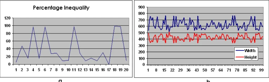
Differential Cryptanalysis attempts to develop a pattern or a relationship between unit changes in plaintext and the ciphertext. Higher the diffusion, higher is the complexity of a differential attack. A good measure of diffusion is the Percentage Inequality P I of two ciphertexts img0 and img00, the former derived from the original plaintextimgand the latter by an unit change on img. The following equation defines P I,
P I = (N DP ×100)/(W ×H) (2)
whereN DP is the number of pixels that differ inimg00 as compared to the corresponding pixels inimg0. If the value of P I between two ciphertexts is high, then Diffusion is said to be high. Also, if this value, for various such ciphertext pairs changes randomly without exhibiting a pattern, a differential attack becomes practically impossible. Figure 4a depictsPIvalues for 20 different ciphertexts measured against
Fig.4: a. Percentage Inequality b. Variation of W0 andH0 against key1 for Lena Image
While Diffusion complicates the relationship between the plaintext and the ciphertext,Confusionachieves the same between the ciphertext and the encryption key. In the proposed scheme, the key is not directly operated on the plaintext bits, rather used as seeds to generate random permutations. The random permutations are used as subkeys to arrange pixel position information and generate colour bit map, altering the basic structure of the plaintext. The final random transposition of ciphertext bytes obfuscates the relation between pixel position ordering on key1. Cryptographically Secure Random Permutations are characterised by a huge change in the permutation order, for a small change in the seed, complicating the Key-Ciphertext relationship. Also, it has been discussed that retrieval of keys from the permutations
RPs, T P and SP is practically impossible. This complicates the key-ciphertext relationship, resulting in high degree of Confusion. Strict Key Avalanche Criterion (SKAC), for a fixed plaintext block, each bit of the ciphertext block changes with a probability of one half when any bit of the key changes. A one bit change in the key, would generate totally unrelated random permutations, resulting in a huge change in the ciphertext, satisfying SKAC. As key1 changes, bit pattern in the CBM changes altering the content and the size of the ciphertext. This completely alters the values of W0 and H0. Figure 4b illustrates the change in W0 and H0 due to unit changes in key1. It can be noted that the change in W0 and H0 does not follow any pattern.
6 SIMULATION RESULTS
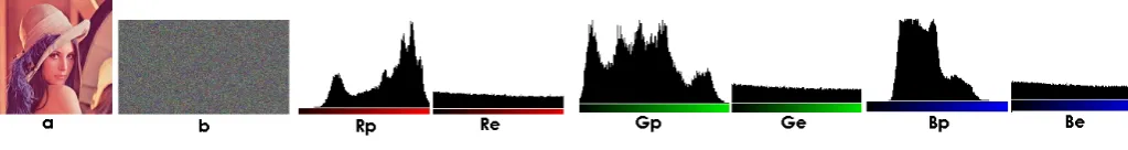
This section provides the experimental results of a basic-unoptimised implementation of the proposed scheme. The experiments were conducted on a 1.83GHz Intel Centrino Duo Processor with 1GB memory. Figure 5 depicts the input image ’Lena’ and its encrypted form. The values ofkey1andkey2are0.298760 and0.514984respectively. It shall be noted that the encrypted image (b) suggest the change in the width and height of the ciphertext. Figures Rp and Re, Gp and Ge, Bp and Be illustrate the histograms of the R, G and B components respectively of the plaintext and ciphertext. It shall be noted that the histograms of the encrypted image suggest an uniform distribution and significant difference of the RGB components of the ciphertext as compared to the plaintext, a desirable property of any encryption scheme.
Fig 5: Lena - Plain Image, Cipher Image and RGB Histogram of plain and cipher image
Images of different width and height combinations have been considered for experiments, each being encrypted with a different set of keys. Table 1 presents the plaintext and the ciphertext properties, the encryption time (ET) and the decryption time (DT) in seconds for a selected set of images with different size and N RP requirements.
Img W×H W0×H0 N RP p ET DT
1 512×512 535×491 21 0 5.0 4.7 2 640×480 602×507 703 2 5.5 4.8 3 1024×786 1141×658 1991 1 6.4 5.4 4 2816×2112 2841×2291 258 41 19.5 14.8 5 3648×2736 4395×2404 5712 17 22.0 19.1
Table 1 - Encryption - Decryption Time
7 CONCLUSION AND FUTUREWORK
The flavour of the algorithm specified in this paper assumes a 24 bit RGB colour. Future work includes research on the number of bits used to represent a colour. 24 bit values need not always result in optimal ciphertexts when the algorithm is applied for digital data other than images. Also,the enhancement proposed as part of Section 4 can be analysed to derive the factor by which the cryptanalytic complexity is increased.
APPENDIX
DERIVATION:N RP
N RP can be mathematically defined as follows. The minimum value of N RP is 1. This is because, even if all the pixels bear the same colour (when no colour order can be defined), RP1 is necessary to create
CBM. In case of multicoloured images, If the pixels are grouped based on the colour and sorted on the group size, thenN RP is the size of the group second in the list starting from the maximum size. If there are multiple sets with the maximum number of pixels, then N RP is the size of one such set. If a(i),
∀0≤i<224RGB colours, denotes the number of pixels of colouri, thenN RP is given by the following.
1) pixmax =max
a(0),a(1), . . . ,a 224−1 2) MultisetU=
i:a(i) =pixmax,∀0≤i<224 3) pixsmax=max
n
a(i),∀0≤i<224 o
− {pixmax}
4)
NRP=
pixmax, size(U)≥2
pixsmax, size(U) = 1
1, otherwise
MATHEMATICAL MODEL OF ENCRYPTIONALGORITHM
The encryption algorithm encrypts plain imageimgwith widthW, heightH and(W ×H)≥1.img(x, y), 0≤x < W,0≤y < H, be the 24 bitRGB colour level ofimgat the position(x, y). The scheme is a 2 key
Secret Key Algorithm. It operates on the input plain imageimg, the two keyskey1andkey2 and generates the encrypted imageimg0 with(W0×H0) pixels. The proposed encryption scheme is defined as follows. Note that the pixels of the plain image are always scanned from LefttoRight and from Topto Bottom, as in a Raster Scan. Let
1) nocrepresent the number of distinct colours in plain image img
2) function b indicate the presence of any colour C in img. Value b(C), ∀ 0 ≤C <224 colour values, is ’1’ if at least one pixel in imgbearsC, ’0’, otherwise.
3) function q be such that q(C), ∀ 0 ≤ C < 224 RGB levels, denotes a number ne, such that, at any point in the encryption process, exactly ne number of pixels of colour C have been placed in the
P os vector. Note that, (0≤q(C)≤a(C))when (b(C) = 1) and (q(C) = 0) when(b(C) = 0)
4) function GetCol be such that for any integer i≥0, GetCol(i) returns the (i+ 1)th colour Ci from
the vector CV (depicted in Figure 1), such that there exists atleast one pixel bearing Ci, which is
yet to be placed in theP os vector.
5) function GetP osbe such that for any colour 0≤C <224, GetP os(C, k) returns P osk, the(k+ 1)th
entry of theP os vector, composed of(x, y, f lg) values of a pixel bearing colourC. This function is defined as follows:
1.q(C) =q(C) + 1, if(b(C) = 1)∧(q(C)≤a(C)) 2.noc=noc−1, if(b(C) = 1)∧(q(C) =a(C))
3. P osk=
n w
q(C), hq(C),0
, if (b(C) = 1)∧(q(C)< a(C))
wq(C), hq(C),1
, if (b(C) = 1)∧(q(C) =a(C))
wherewq(C) andhq(C) represent respectively the width wand the height hof theq(C)th pixel such thatimg wq(C), hq(C)
=C
The Encryption Algorithm is defined as follows:
Step 1: Create the P os vector [P os0, P os1, . . . , P osW×H−1] by the following three steps. Initially, k = 0,
n= 2. kis incremented after each P os entry
1.P osk=GetP os(CV[RP1[j]], k),∀0 ≤j < 224, whereRP1=RP key1,0,224
2.P osk=GetP os(GetCol(RPn[j]), k),(∀0≤j < noc)and(∀2≤n < N RP), where anyRPn=RP(key1, n, noc)
Step 2: Create CBM =
B0, B1, . . . , B224−1
, where any Bj=b(RP1[j]),∀0≤j <224
Step 3: Assuming P os and CBM are digitally represented, Create P B = [P os, CBM]. Let pb be the size
of vector P B.
Step 4:Let (p)be the number of padding bytes in the encrypted image. The padding bytes are given by
the vector P =[P0, P1, . . . , Pp−1]. Create P B0 =[P B, P0, P1, . . . , Pp−1].(pb+p)gives the size of P B0
Step 5: Insert W1, H1, W2 and H2 within vector P B0, at positions given by SP[0],SP[1],SP[2] and SP[3] respectively, to create vector F0, composed of (pb+p+ 4)bytes. SP =RP(key2,0,(pb+p))
Step 6: Shuffle F0 using permutation T P to create F =
F0, F1, . . . , Ff−1
, where any Fi =FT P0 [i]. Choose
W0 andH0 such that f=(W0×H0×3)=(pb+p+ 4). T P =RP(key2,1, f)
Step 7: Create encrypted image img0 of size W0×H0,
img0(x, y)=[Fi, Fi+1, Fi+2], wherei= (x×W0×3) + (y×3),∀0≤x < W0,0≤y < H0
img0(x, y) is represented as a 24 bit number with Fi being the MSB. Number of pixels in img0 is nop= (W0×H0)/3.
Step 8:Choose any two integral factors nop1 andnop2 of nopsuch that (nop1×nop2) =nop. Then W0=nop1 and H0=nop2. Note that this step is optional.
DERIVATION:M,T ANDM T
Number of invalid size byte sets that can be chosen from a bin off bytes, of which z bytes carry value 0 andu bytes carry value greater than thresholdt is derived as follows.
Let Bn be thenth byte chosen. Note that B1 =W1,B2 =H2,B3=W2 andB4 =H2. Let Z represent a byte with value 0, and N, a byte with a non-zero positive value. It shall be noted that m = (f −z) are the number of non-zero bytes available. There are (z) ways to choose the first Z, (z−1) ways for the second and so on. Similarly (m) ways for the firstN, (m−1)ways for the second and so on.
Since 4 bytes have to be randomly chosen from the bin, there can be 16 distinct possibilities, of which some are invalid. Byte combinations which have both B1 = 0 and B3 = 0 or both B2 = 0 and
B4 = 0 result in a value 0 for W or H respectively. Such combinations shall be discarded. Invalid byte combination B1B3B2B4 that result in value W or H = 0 and the number of ways Num in which each invalid combination be chosen as a size byte set, has been depicted in the Table 2.
B1B3B2B4 Num
ZZZZ (z) (z−1) (z−2) (z−3)
ZZZN (z) (z−1) (z−2) (m)
ZZN Z (z) (z−1) (m) (z−2)
ZZN N (z) (z−1) (m) (m−1)
ZN ZZ (z) (m) (z−1) (z−2)
N ZZZ (m) (z) (z−1) (z−2)
N N ZZ (m) (m−1) (z) (z−1)
Table 2. No. of invalid size byte choices withH= 0orW= 0
Summing the invalids, the number of 4 byte sets M, resulting in a value 0 for both or any of W and
H is
M=zP
4+ 4 (f−z) (zP3) + 2 (zP2) (f−z)P2
On the same lines, the number of 4 byte sets T, resulting in W2 > t or H2 > t can be derived. If L represents a byte B < t, and G, a byte B > t, all byte combinations which have B3 > t or B4 > t like
LGGGand LLLG are invalid. Adding all such invalid combinations, the value ofT is
uP
4+ 4 (f−u) (uP3) + 5 (uP2) (f−u)P2+ 2 (u) (f−u)P3
Byte combinations which qualify under both the above mentioned categories of invalid size byte sets, likeZZLG, are invalidated twice. The number of such combinationsMThave to be subtracted once from
M+T. MT is defined by the following equation.
M T =2 (u) (f−u) (zP
REFERENCES
[1] W. Stallings,Cryptography and Network Security principles and practices, third ed.: Pearson Education, 2003.
[2] D. Knuth,The Art of Computer Programming, Volume 2: Seminumerical Algorithms, Reading, MA: Addison-Wesley, 1998.
[3] N.D. Jorstad, L.T. Smith, Jr., “Cryptographic Algorithm Metrics,” Institute for Defense Analyses Science and Technology Division ,January. 1997. [4] C. Shannon, “Communication Theory of Secrecy Systems,”Bell Systems Technical Journal,no. 4, 1949.
[5] J. Cheng; J.I. Guo, “A new chaotic key-based design for image encryption and decryption,”The 2000 IEEE International Symposium on Circuits and Systems, 2000. Proceedings. ISCAS 2000 Geneva,vol.4, no. 4, pp. 49 - 52, May. 2000.
[6] D. A. Osvik, A. Shamir, E. Tromer, Cache Attacks and Countermeasures: the Case of AES, November, 2005. available at http://theory.csail.mit.edu/˜tromer/papers/cache.pdf.
[7] SJ. Li and X. Zheng, “Cryptanalysis of a chaotic image encryption method,” The 2002 IEEE International Symposium on Circuits and Systems Proceedings 2002. ISCAS 2002 Scottsdale, Arizona,vol. 1, 2006
[8] R. B. Davies,Newran02C - a random number generator library, April, 2006. available at http://www.robertnz.net/.
[9] Anatoliy Kuznetsov,D-Gap Compression, 2002. available at http://bmagic.sourceforge.net/dGap.html. [10] S.K. Sahni,Data Structures, Algorithms, and Applications in C++,, Second Edition, McGraw Hill, NY, 2005.
[11] Shiguo Lion, Jinsheng Sun and Zhiquan Wang, “A Novel Image Encryption Scheme Based-on JPEG Encoding,” Proceedings of the Eighth International Conference on Information Visualisation (IV04),2004
[12] J.A. Munoz Rodrguez and R. Rodrguez-Vera, “Image encryption based on phase encoding by means of a fringe pattern and computational algorithms,” REVISTA MEXICANA DE FISICA 52 (1),pp. 53-63, Feb. 2004
[13] A. Mitra, Y. V. Subba Rao and S. R. M. Prasanna, “A New Image Encryption Approach using Combinational Permutation Techniques,”
INTERNATIONAL JOURNAL OF COMPUTER SCIENCE,vol. 1, no. 5, 2006
[14] W. Diffie and M. E. Hellman, “New Directions in Cryptography,”IEEE Transactions Information Theory,vol. 22, no. 6, pp. 644-654, Nov. 1976.
[15] P. P. Dang and P. M. Chau, “Image Encryption for Secure Internet Multimedia Applications,”IEEE Transactions Consumer Electronics,vol. 46, no. 3, pp. 395-403, Aug. 2000.
[16] R. B. Davies,COPACOBANA, a$10,000 DES cracker based on FPGAs by the Universities of Bochum and Kiel, December, 2006. available at http://www.copacobana.org/.
[17] A. Fuster and L. J. Garcia, “An Efficient Algorithm to Generate Binary Sequences for Cryptographic Purposes,”Theoretical Computer Science
259, pp. 679-688, 2001.
[18] Ronald L. Rivest, “The RC5 Encryption Algorithm,”, March. 1997.
[19] Min-Sung Koh, Esteban Rodriguez-Marek, Claudio Talarico,A NOVEL DATA DEPENDENT MULTIMEDIA ENCRYPTION ALGORITHM SECURE AGAINST CHOSEN-PLAINTEXT ATTACKS, ICME 2007.
Karthik Chandrashekar Iyerreceived the Bachelor of Engineering degree in Computer Science from the Vishweshwaraya Technological University, Karnataka, India in 2004. Currently, he is a Senior Engineer in the DSP Software Center, NXP Semiconductors (formerly Philips Semiconductors), Bangalore, India. His interests include Embedded Multimedia Systems, Digital Rights Management, Video Post Processing, Cryptography and Network Security.