Scholarship@Western
Scholarship@Western
Electronic Thesis and Dissertation Repository
10-23-2019 1:30 PM
Hydrodynamics of Liquid-Solid and Three-Phase Inverse
Hydrodynamics of Liquid-Solid and Three-Phase Inverse
Circulating Fluidized Beds
Circulating Fluidized Beds
Tian Nan
The University of Western Ontario
Supervisor Zhu, Jesse
The University of Western Ontario
Graduate Program in Chemical and Biochemical Engineering
A thesis submitted in partial fulfillment of the requirements for the degree in Doctor of Philosophy
© Tian Nan 2019
Follow this and additional works at: https://ir.lib.uwo.ca/etd
Part of the Catalysis and Reaction Engineering Commons
Recommended Citation Recommended Citation
Nan, Tian, "Hydrodynamics of Liquid-Solid and Three-Phase Inverse Circulating Fluidized Beds" (2019). Electronic Thesis and Dissertation Repository. 6663.
https://ir.lib.uwo.ca/etd/6663
The hydrodynamics of inverse liquid-solid circulating fluidized bed (ILSCFB) is
experimentally studied in a 5.4 m tall and 0.076 m ID column. 5 types of low density particles
are investigated with different particle terminal velocities.
Solids holdup distribution is found to be uniform in a wide range of superficial liquid velocities
and over 10 solid circulation rates. Average solids hold is not sensitive to particle properties.
Clustering phenomenon is found to be significant affecting the slip velocity in the ILSCFB.
And the cluster phenomenon is directly related to particle Reynolds number (Ret). Particles
with little Ret tends to have higher slip velocity which is believed as an indicator of clustering
phenomenon. A modified Richardson-Zaki equation is proposed for the prediction of solids
holdup in ILSCFB
Comparative study between upward and inverse liquid-solid CFBs is conducted. General
hydrodynamics is found to be similar. Axial solids holdup is uniform in both systems. Radial
flow structure is also uniform although some decreasing trend from center to the wall is
observed in inverse liquid-solid circulating fluidized bed due to the effect of lifting force.
Residence time per unit height is used as a tool to compare different reactor performance, and
also compare particle properties. Particles with little Retwill lead to less homogeneous behavior
in the circulating fluidized bed for both heavy and low density particles.
A new type of circulating fluidized bed, conventional circulating fluidized bed, operating
below particle terminal velocity, is proposed and experimentally investigated. Solids holdup is
found to be significantly increased compared with both conventional fluidization and regular
circulating fluidization. And better solids holdup control is achieved with the help of solids
circulation.
Preliminary study on the counter-current flow of liquid and solids is carried out with both
heavy and density particles. Inverse gas-liquid-solid circulating fluidized bed is proposed, and
A detail flow regimes map is presented and discussed based on flow directions of liquid and
solids. The studied configurations of liquid-solid fluidization systems in this research are
highlighted in the flow regimes map, which greatly enriches the operating modes of
liquid-solid fluidization.
.
Keywords
Inverse Fluidization, Circulating Fluidized Bed, Fluidization Regime, Gas-Liquid-Solid
Summary for Lay Audience
In chemical and biochemical processes, multiphase contact is of great importance for mass
transfer, heat transfer and reaction performance. And fluidized bed is an approved candidate
due to its intensified solids movement within the fluid. This study focuses on the
hydrodynamics of multiple liquid fluidization systems which covers both co-current and
counter-current flow of liquid and solid with both light and heavy density particles in relative
to liquid.
In Inverse Liquid-Solid Circulating Fluidized Bed, solids holdup distribution is found to be
uniform both axially and radially. And solids holdup is increasing solid circulating rate and
decreasing with superficial liquid velocity. The effects of particle properties are not significant
in determining solids holdup, but quite notable in affecting the slip velocity between liquid and
solid. A model is presented for the prediction of solids holdup.
A new type of Liquid-Solid Circulating Fluidized Bed is proposed that can operate below
particle terminal is proposed that can increase solids holdup significantly.
Preliminary study on the counter-current flow of liquid and solids were studied with both heavy
and density particles. Inverse gas-liquid-solid circulating fluidized bed is proposed and
experimentally investigated the hydrodynamics.
Comparative study on the flow of heavy and low density particles were conducted and some
clustering phenomenon were believed to exist in particles with low terminal velocity. And a
discussion on liquid fluidization based on Four-Quadrant Fluidization Regime Map is
conducted at the end that summarized the studied systems and may also lead to findings in new
Co-Authorship Statement
Title: Hydrodynamics in Inverse Liquid-Solid Circulating Fluidized Bed
Author: Tian Nan, Jesse Zhu, Dominic Pjontek
Tian Nan designed and performed the major part of the experiment and carried out data
analysis under the guidance of advisor Dr. Jesse Zhu and Dr. Dominic Pjontek. All
drafts of this manuscript were written by Tian Nan. Modifications were carried out
under close supervision of advisor Dr. J. Zhu. The final version of this article is ready
for submission.
Title: Comparative study of inverse and upward Liquid-Solid Circulating Beds
Author: Tian Nan, Jesse Zhu
Tian Nan designed and performed the major part of the experiment and carried out data
analysis under the guidance of advisor Dr. Jesse Zhu. All drafts of this manuscript were
written by Tian Nan. Modifications were carried out under close supervision of advisor
Dr. J. Zhu. The final version of this article is to be submitted.
Title: Hydrodynamics study on a Conventional Circulating Fluidized Bed
Author: Tian Nan, Jesse Zhu
Tian Nan designed and performed the major part of the experiment and carried out data
analysis under the guidance of advisor Dr. Jesse Zhu. All the experimental work was
undertaken by Tian Nan. All drafts of this manuscript were written by Tian Nan.
Modifications were carried out under close supervision of advisor Dr. Jesse. Zhu. The
final version of this article is to be submitted.
Title: Counter-Current flow of liquid and solid in circulating fluidized beds
Author: Tian Nan, Jesse Zhu
undertaken by Tian Nan. All drafts of this manuscript were written by Tian Nan.
Modifications were carried out under close supervision of advisor Dr. Jesse. Zhu. The
final version of this article is to be submitted.
Title: On the basic hydrodynamics of Inverse Gas-Liquid-Solid Circulating Fluidized bed
Author: Tian Nan, Jesse Zhu, Dominic Pjontek
The experimental setup of Inverse Gas-Liquid-Solid Circulating Fluidized Bed was
designed and modified by Tian Nan together with Jianzhang Wen under the guidance
of advisor Dr. Jesse. Zhu. All the experimental work was undertaken by Tian Nan. All
drafts of this manuscript were written by Tian Nan. Modifications were carried out
under close supervision of advisor Dr. Jesse. Zhu and Dr. Dominic Pjontek. The final
Acknowledgments
First and foremost, I would like to thank my supervisor Dr. Jesse Zhu for the generously
financial support. Nothing can be achieved without his expertise and mentorship in research
and life.
I would like to express my sincerest gratitude and thanks to Dr. Dominic Pjontek for his
guidance and extensive support through many aspects of my life at Western University. I am
inspired by his attitudes towards academia and teaching.
I would like to acknowledge Saleh Ahmed Srabet for his help with experiment design and data
analysis. And also, the technical staff in our research group, Jianzhang Wen, Danni Bao and
George Zhang for their assistance and service.
Thanks to Gong Zhang, Jiaqi Huang, Haohao Zhou, Sylena Song, Lukang Sun, Jing Wang for
their efforts in helping with experiment measurement and operation.
Many thanks go to Dr. Xiaoyang Wei and Dr. Zhijie Fu for the many late-night heated
discussions we had ever since the starting of our Ph.D. life
I’d like to express my gratitude to Mengze Zhang, Wenhao Lian and Hanlin Wang for their
patience and understanding to help me struggling through the final period on my Ph.D.
Last but not the least, I’d like to thank my parents for their unconditional love. They support
Table of Contents
Abstract ... ii
Summary for Lay Audience ... iv
Co-Authorship Statement... v
Acknowledgments... vii
Table of Contents ... viii
List of Tables ... xiv
List of Figures ... xv
List of Appendices ... xx
Chapter 1 ... 1
1 General Introduction ... 1
Introduction ... 1
Research objective ... 4
Thesis Structure ... 5
Reference... 6
Chapter 2 ... 10
2 Literature Review ... 10
Fundamental ... 10
Superficial liquid velocity ... 10
Interstitial liquid velocity ... 10
Particle terminal velocity ... 11
Solid circulation rate ... 12
Fluidization regimes... 13
Hydrodynamics of LSCFB ... 13
Onset velocity ... 15
Pressure balance in LSCFB ... 16
Transition Regime ... 16
Cluster in liquid-solid circulating fluidized bed ... 17
Hydrodynamics of Inverse Conventional fluidization ... 18
Behavior of low density particles in liquid ... 19
Richardson-Zaki equation ... 20
Hydrodynamics of inverse three-phase fluidization ... 21
Nomenclature ... 23
Reference... 25
Chapter 3 ... 28
3 Hydrodynamics of Inverse Liquid-Solid Circulating Fluidized Bed ... 28
Abstract ... 28
Introduction ... 28
Experiment ... 30
Apparatus ... 30
Particle properties ... 32
Results and Discussion ... 32
Particle terminal velocity ... 32
Axial flow structure ... 34
Radial flow structure ... 45
Average solids holdup and particle property effects ... 54
Slip velocity ... 57
Prediction of solids holdup ... 59
Reference... 67
Chapter 4 ... 70
4 Comparative Study of Inverse and Upward Liquid-Solid Circulating Fluidized Bed . 70 Abstract ... 70
Introduction ... 70
Experiment setup ... 74
Operation of LSCFB and ILSCFB ... 74
Residence time per unit height ... 75
Results and discussion ... 76
Change of Ts, Tl with Us and Ul ... 76
Particle property effects Ts ... 79
Comparison between CCFB and LSCFB ... 81
Change of Ts/Tl with Ul in LSCFB and ILSCFB ... 81
Significance of Ts, Tl and Ts/Tl ... 85
Failure of Richardson-Zaki equation in (I)-LSCFB... 85
Comparison of Ts/Tl in Gas-Solid CFB ... 87
Conclusions and recommendations... 87
Nomenclature ... 89
Reference... 91
Chapter 5 ... 93
5 Hydrodynamics of inverse liquid-solid circulating fluidized bed below particle terminal velocity ... 93
Abstract ... 93
Introduction ... 93
Conventional fluidization... 94
Concept of CCFB ... 95
Experiment procedures ... 97
Results and discussion ... 99
Axial Solids holdup distribution ... 101
Apparent slip velocity ... 103
Bed Intensification factor ... 105
The connection between conventional fluidization and circulating fluidization - CCFB... 107
Solids circulation rate (Us) ... 109
Richardson-Zaki equation in CCFB... 110
Conclusion and recommendation ... 112
Nomenclature ... 113
Reference... 115
Chapter 6 ... 119
6 Counter-Current flow in (I)-LSCFB systems ... 119
Abstract ... 119
Introduction ... 119
Experiment setup ... 122
Operation of solids down, liquid up ... 122
Operation of solids up and liquid down ... 123
Results and discussion ... 125
Force balance of particles falling ... 126
Effects of Ul ... 126
Effects of Us ... 129
Nomenclature ... 134
Reference... 136
Chapter 7 ... 138
7 Preliminary study of an inverse gas-liquid-solid circulating fluidized bed ... 138
Abstract ... 138
Introduction ... 138
Experiment setup ... 141
Operation of IGLSCFB ... 142
Measurement of phase holdups ... 143
Gas-Liquid experiment and observation ... 144
Phase holdup distributions and mixture density ... 147
Average solids holdup at different operation conditions ... 148
Comparison between the behavior of gas and solid in IGLSCFB ... 150
Comparison between IGLSCFB and ILSCFB ... 151
Conclusions and recommendations... 152
Nomenclature ... 154
Reference... 156
Chapter 8 ... 159
8 General Discussion... 159
Development of Four-Quadrant Fluidization Regime map ... 159
Description of each Quadrant ... 162
Projection of solids holdup in different modes of operation... 165
Critical solids flowrates and liquid velocities ... 172
Stagnant liquid flow ... 174
Supporting flow ... 174
Transition between regimes ... 175
Connection between CCFB and LSCFB... 175
Connection between counter-current flow and circulating fluidized bed 176 Feasible operating conditions of heavy density particles ... 177
Feasible operating conditions of low density particles ... 178
Nomenclature ... 179
Chapter 9 ... 181
9 Conclusions and Recommendations ... 181
Conclusions ... 181
Recommendations ... 182
Appendices ... 185
A. Materials and Method ... 185
B. Average solids holdup of each particle ... 196
C. Published article ... 201
List of Tables
Table 3.2-1 Particle properties ... 32
Table 3.4-1 Fitted n and k in modified Richardson-Zaki equation ... 62
Table 4.1-1 Comparison of Ts, Tl and Ts/Tl at constant solids holdup ... 73
Table 5.2-1 Particle properties ... 97
Table 8.2-1 Flow directions of solids and liquid in four-quadrant flow regimes map ... 164
Table 8.4-1 Summary on different types of flow ... 175
List of Figures
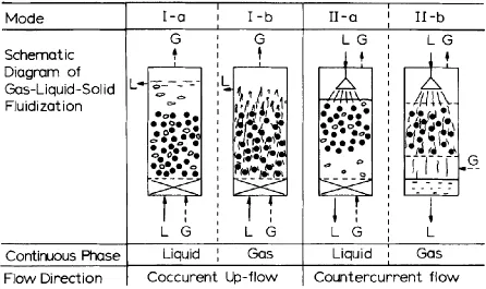
Figure 1.1.1 Modes of Gas-Liquid-Solid Fluidization (Muroyama and Fan 1985) ... 1
Figure 1.1.2 Four-Quadrant flow regimes map based on flow directions of liquid and solids 3 Figure 2.2.1 Liquid-solid fluidization regime map based on dimensionless particle diameter and dimensionless superficial liquid velocity (J. Wang et al. 2019) ... 13
Figure 2.3.1 Axial solids holdup distribution in LSCFB at constant solid circulation rate for different particles (Sang and Zhu 2012) ... 14
Figure 2.3.2 Solids holdup radial distribution in LSCFB riser (Sang and Zhu 2012) ... 15
Figure 2.3.3 Typical Cluster in liquid-solid transport bed obtained from PIV with time interval of 0.6s (Chen et al. 1991) ... 18
Figure 2.4.1 Flow regime map for the inverse three-phase fluidized bed based on Ul and Ug. (A) fixed or partially fluidized bed; (B) fluidized bed with dispersed bubbles; (C) fluidized bed with transition to coalescing bubble flow. (Buffière and Moletta 1999) ... 22
Figure 3.2.1 Schematic diagram of inverse liquid-solid circulating fluidized bed ... 31
Figure 3.3.1 The relationship between ln(Ul) and ln(εl) of studied particles, ... 33
Figure 3.3.2 Axial solids holdup distribution of EPS28 ... 36
Figure 3.3.3 Axial solids holdup distribution of EPS122 ... 37
Figure 3.3.4 Axial solids holdup distribution of EPS303 ... 38
Figure 3.3.5 Axial solids holdup distribution of EPS638 ... 39
Figure 3.3.6 Effects of Ul on axial solids holdup distribution of EPS28. ... 40
Figure 3.3.8 Axial solids holdup distribution of different particles under different constant Ul
and Us ... 42
Figure 3.3.9 Axial solids holdup distribution under different Ul -Ut and ... 44
Figure 3.3.10 Solids holdup radial distribution of five types of particles ... 45
Figure 3.3.11 Radial solids holdup distribution of EPS28... 47
Figure 3.3.12 Local particle velocity of EPS28 ... 48
Figure 3.3.13 Radial flow structure of EPS 122 ... 49
Figure 3.3.14 Radial flow structure of EPS 303 ... 50
Figure 3.3.15 Radial flow structure of EPS636 ... 51
Figure 3.3.16 Change of average particle velocity with Us ... 52
Figure 3.3.17 Change of average particle velocity with Us under difference Ul ... 53
Figure 3.3.18 Effects of particle properties on average solids holdup in the ILSCFB at constant superficial liquid velocity ... 54
Figure 3.3.19 Effects of particle properties on average solids holdup in the ILSCFB at constant solids circulation rate ... 55
Figure 3.3.20 3D map of the relationship between solids holdup and Ul, Us ... 56
Figure 3.3.21 Effects of particle property on Uslip/Ut under different solids holdup ... 58
Figure 3.3.22 Clustering phenomenon observed in ILSCFB ... 59
Figure 3.4.1 Predicted solids holdup vs experiment solids holdup with original Richardson-Zaki equation, Ut and n were obtained from conventional bed expansion experiment ... 61
Figure 4.1.1 The change of average solids holdup with Ul when Us = 1cm/s in LSCFB ... 72
Figure 4.2.1 Schematic diagram of ILSCFB ... 74
Figure 4.2.2 Schematic diagram of LSCFB ... 75
Figure 4.3.1 Change of Ts with Us under different Ul in ILSCFB ... 76
Figure 4.3.2 Change of Ts with Us under different Ul in LSCFB ... 77
Figure 4.3.3 Change of Tl with Us under different Ul in ILSCFB ... 78
Figure 4.3.4 Change of Ts of different particles ... 79
Figure 4.3.5 Comparison between LSCFB and ILSCFB ... 80
Figure 4.3.6 Change of Ts/Tl with Ul in ILSCFB ... 82
Figure 4.3.7 Change of Ts/Tl with Ul in LSCFB ... 83
Figure 4.3.8 Change of Ts/Tl in gas-solid CFB riser(Wang et al. 2014)... 87
Figure 5.3.1 Schematic diagram of inverse CCFB ... 99
Figure 5.3.2 Solids holdup vs superficial liquid velocity at different flow regimes ... 100
Figure 5.3.3 Axial solids holdup distribution in inverse CCFB of two types of low density particles. ... 102
Figure 5.3.4 Axial distribution of solids holdup, ρ = 122 kg/m3 ... 103
Figure 5.3.5 The change of slip velocity with Us of EPS122 ... 104
Figure 5.3.6 The change of slip velocity with Us of EPS122 ... 104
Figure 5.3.7 The change of Bed Intensification Factor with Us ... 106
Figure 5.3.9 The change of average solids holdup with Us in inverse CCFB and LSCFB .. 108
Figure 5.3.10 Relationship between ln(Uslip /Ut) with ln(εl) in inverse CCFB ... 111
Figure 6.1.1 Schematic diagram of liquid-solid circulating fluidized bed ... 121
Figure 6.2.1 Schematic diagram of solids falling down in upflow liquid... 123
Figure 6.2.2 Schematic diagram of solids rising in downflow liquid in ILSCFB ... 124
Figure 6.3.1 Force balance on heavy particles falling in upflow liquid ... 126
Figure 6.3.2 Axial solids holdup in counter-current flow of heavy solids at different upflow liquid and constant superficial solid velocity. (a), Us = 1.89 cm/s, (b) Us = 5.29 cm/s, (c) Us = 8.57 cm/s ... 128
Figure 6.3.3 The change of average solids holdup with Ul at constant Us of heavy particles ... 130
Figure 6.3.4 The change of average solids holdup with Us at constant Us of low density particles ... 130
Figure 6.4.1 Axial solids holdup distribution of light particles rising ... 132
Figure 7.2.1 Schematic diagram of inverse gas-liquid-solid circulating fluidized bed ... 141
Figure 7.3.1 Gas holdup vs downflow liquid velocity at different superficial gas velocity . 144 Figure 7.3.2 Gas holdup axial distribution at different downflow liquid velocity when Ug = 4.3 mm/s ... 146
Figure 7.3.3 Mixture density of IGLSCFB ... 148
Figure 7.3.4 Solids holdup (εs) versus solids circulation (Us) rate at constant superficial liquid velocity (Ul) and superficial gas velocity (Ug) ... 149
Figure 8.1.1 Four-Quadrant Fluidization Regimes Map with operating liquid velocity beyond
particle terminal velocity. ... 160
Figure 8.1.2 Four-Quadrant Fluidization Regimes Map with conventional circulating fluidized bed. ... 161
Figure 8.1.3 Four-Quadrant Fluidization Regimes Map ... 162
Figure 8.3.1 Projection of εs versus Us based on Richardson-Zaki equation (n = 4) ... 167
Figure 8.3.2 Projection of εs versus Ul/Ut based on Richardson-Zaki equation (n = 4) ... 168
Figure 8.3.3 Effects of n on the change of εs with Us in circulating fluidized bed below Ut 170 Figure 8.3.4 Effects of n on the change of εs with Us in LSCFB ... 171
Figure 8.6.1 Feasible operating condition of heavy density particles... 177
Figure 8.7.1 Feasible operating condition of low density particles ... 178
Figure A.1 Schematic diagram of inverse liquid-solid circulating fluidized bed ... 188
Figure A.2 Schematic diagram of CCFB ... 191
List of Appendices
Appendix B-1 Average solids holdup data of EPS122 ... 196
Appendix B-2 Average solids holdup data of EPS638 ... 197
Appendix B-3 Average solids holdup data of EPS303 ... 198
Appendix B-4 Average solids holdup data of EPS28 ... 199
Appendix B-5 Average solids holdup data of PS1020 ... 200
Appendix B-1 Published article in ILSCFB with previous student ... 201
Chapter 1
1
General Introduction
Introduction
Liquid fluidization has becoming increasingly important in human history since 19th century in
mineral dressing industry to today’s environment and energy industry, due to its versatility and
applicability for phase contact (Epstein 2002). With the development over the years, gas phase is
also introduced as the third phase. Liquid-Solid fluidization and Gas-Liquid-Solid fluidization can
be used for physical processes exemplified by particle classification, crystallization (van Dijk and
Braakensiek 1985) and leaching (Kwauk 1991) etc., and chemical processes such as fluidized bed
electrodes (Goff et al. 1969) and fluidized bed bioreactors (Nelson, Nakhla, and Zhu 2017;
Chavarie and Karamanev 1986).
The demand is rising for the proper design and operation of different types of liquid fluidized bed
to satisfy the booming environmental and energy industries (Zhu et al. 2000). Fan has summarized
different types of two-phase and three-phase fluidized bed based on categorization of continuous
phase and flow direction of gas phase and liquid phase as shown in Figure 1.1.1. And in the age
of 80s, many studies were focusing on the bubble behavior in three-phase fluidized bed ;Tzeng,
Chen, and Fan 1993; Tsuchiya et al. 1997; Yang, Du, and Fan 2007; Chen, Reese, and Fan 1994),
while the study on particles are not well addressed. In recent years, more applications have been
developed that require intensive solid-liquid contact. The flow of solids phase has start to draw
more attention. Based on that, liquid-solid circulating fluidized bed (LSCFB) (Zheng et al. 1999;
Zheng and Zhu 2001; Lan et al. 2000; Zheng and Zhu 2000a, 2000b; Sang and Zhu 2012; Trivedi,
Bassi, and Zhu 2006) and gas-liquid-solid circulating fluidized bed (GLSCFB) have been
developed (Razzak, Zhu, and Barghi 2010, 2009; Zhu et al. 2000), where solids phase is
continuously flowing through the fluidized bed. The uniform distribution of solids and high contact
efficiency between solid and liquid have justified their potential applications for ion exchange
process (Lan et al. 2002; M. Patel et al. 2008), waste water treatment (Eldyasti et al. 2010; A. Patel,
Zhu, and Nakhla 2006; Nelson, Nakhla, and Zhu 2017) and polymerization reaction (Trivedi,
Bassi, and Zhu 2006). Many studies have been carried out to investigate the hydrodynamics of
LSCFB and GLSCFB which are crucial in fluidized bed design and operation. The development
of LSCFB and GLSCFB opens new spectrum in the perspective of liquid based fluidized beds.
Thus, the modes of fluidization could be extended based on the flow directions of solid and liquid
and it is summarized in Figure 1.1.2, which has been proposed by Prof. Jesse Zhu in many
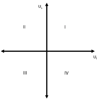
Figure 1.1.2 Four-Quadrant flow regimes map based on flow directions of liquid and solids
The horizontal axis represents liquid flow, and the vertical axis represent solids flow. And in
Quadrant-I both liquid and solids are flowing upwards, while in Quadrant-III both are flowing
downwards.
Conventional fluidization occupies the horizontal axis where there is no solid circulation. LSCFB
take place in Quadrant-I by adding superficial solid velocity to the system. Based on extensive
literature review, 90% study on liquid fluidized lies in Quadrant-I (including the positive
horizontal axis).
With two continuous flow of solids and liquid, multiple combinations of flow directions could
exist in each quadrant of the four-quadrant flow regimes map. Counter-current flow of liquid and
solid will take place in the second and fourth quadrant, and the first and third quadrant will be
fluidization, the change of fluid/particle density ratio is necessary. As recent years, the study of
inverse (downward) fluidization with low density particles have already drawn some attention that
is placed on the left side of the horizontal axis and further extended to Quadrant-III by adding
downward solid circulation
The flow behavior of low density particles has been studied long before in many areas, such as
crystallization and wastewater treatment (Matas, Morris, and Guazzelli 2004; GOTOH 1970;
Saffman 1965; Han and Hunt 1995). Most studies focused on neutrally-buoyant particles, whose
density are slightly smaller than liquid and have small particle diameter. It wasn’t until late 20th
century that inverse fluidization was first extensively studied by Fan and Karamanev etc (Fan,
Muroyama, and Chern 1982; Nikolov and Karamanev 1991; Dimitar G. Karamanev and Nikolov
1992; D. G. Karamanev and Nikolov 1992). Most common fluidized beds, the particles are heavier
than the fluid, thus the gas or liquid always has to flow upward to support the weight of particles.
When particle density is lighter than the fluid, the direction of fluid flow has to be inversed to
fluidize the floating particles, so-called inverse fluidization.
More regimes can be discovered based on this extensive Four-Quadrant Fluidization Regime Map.
The hydrodynamics of each regime, especially of which with low density particles are not well
studied. This study will focus on the hydrodynamics of inverse liquid-solid circulating fluidized
bed in Quadrant-III and fill some blank areas in the Four-Quadrant Fluidization Regime Map.
Research objective
The main objective of this study is to systematically investigate the hydrodynamics of multiple
circulating liquid-solid fluidized bed systems
The secondary objectives are:
• Study the hydrodynamics of inverse liquid-solid circulating fluidized bed experimentally
• Study the hydrodynamics of liquid-solid circulating fluidized bed below particle terminal
velocity
• Investigate the characteristics of the first proposed inverse gas-liquid-solid circulating
• Fulfill the four-quadrant flow regimes map
Thesis Structure
Chapter 2 gives a literature review on conventional liquid-solid fluidization, liquid-solid
circulating fluidization and inverse fluidization, which covers multiple flow conditions in the area
liquid fluidization
Chapter 3 studies hydrodynamics of an inverse liquid-solid circulating fluidized bed with five
types of low density particles. The study on of axial and radial flow structure, average solids
holdup, and particle property effects is covered.
Chapter 4 compares its hydrodynamics of liquid-solid circulating fluidized bed with heavy density
particles based on solids holdup distribution, particle property effects and solids residence time
per unit height.
Chapter 5 proposes the idea of low velocity circulating fluidized bed, called conventional
circulating fluidized bed (CCFB), where solids circulation take place while the system is operating
under particle terminal velocity. And studied the hydrodynamics of inverse CCFB.
Chapter 6 shows some preliminary results of counter-current flow of free-falling and free-rising
particles
Chapter 7 describes some preliminary results in the hydrodynamics of inverse gas-liquid-solid
circulating fluidized bed (IGLSCFB). And compared its hydrodynamics with ILSCFB.
Chapter 8 provide a general discussion on the Four-Quadrant Fluidization Regime map.
Chapter 9 concludes the finding of this research and lists many recommendations in the area of
Reference
Buffière, Pierre, and René Moletta. 1999. “Some Hydrodynamics Characteristics of Inverse
Three Phase Fluidized-Bed Reactors.” Chemical Engineering Science 54 (9): 1233–42.
https://doi.org/10.1016/S0009-2509(98)00436-9.
Chavarie, C, and D Karamanev. 1986. “Use of Inverse Fluidization in Biofilm Reactors.” In
Proc. Int. Conf. on Bioreactor Fluid Dynamics, Cambridge (15-17 April), 181–90.
Chen, R. C., J. Reese, and L.-S. Fan. 1994. “Flow Structure in a Three-Dimensional Bubble
Column and Three-Phase Fluidized Bed.” AIChE Journal 40 (7): 1093–1104.
https://doi.org/10.1002/aic.690400702.
Dijk, J. C. van, and H. Braakensiek. 1985. “Phosphate Removal by Crystallization in a Fluidized
Bed.” Water Science and Technology 17 (2–3): 133–42. https://doi.org/10.2166/wst.1985.0125.
Eldyasti, Ahmed, Nabin Chowdhury, George Nakhla, and Jesse Zhu. 2010. “Biological Nutrient
Removal from Leachate Using a Pilot Liquid–Solid Circulating Fluidized Bed Bioreactor
(LSCFB).” Journal of Hazardous Materials 181 (1–3): 289–97.
https://doi.org/10.1016/J.JHAZMAT.2010.05.010.
Epstein, Norman. 2002. “Applications of Liquid-Solid Fluidization.” International Journal of
Chemical Reactor Engineering 1 (1). https://doi.org/10.2202/1542-6580.1010.
Fan, Liang Shih, Katsuhiko Muroyama, and Song Hsing Chern. 1982. “Hydrodynamics
Characteristics of Inverse Fluidization in Liquid-Solid and Gas-Liquid-Solid Systems.” The
Chemical Engineering Journal 24 (2): 143–50. https://doi.org/10.1016/0300-9467(82)80029-4.
Goff, P. Le., F. Vergnes, F. Coeuret, and J. Bordet. 1969. “APPLICATIONS OF FLUIDIZED BEDS IN ELECTROCHEMISTRY.” Industrial & Engineering Chemistry 61 (10): 8–17.
https://doi.org/10.1021/ie50718a004.
Han, Q., and J.D. Hunt. 1995. “Particle Pushing: Critical Flow Rate Required to Put Particles into Motion.” Journal of Crystal Growth 152 (3): 221–27.
https://doi.org/10.1016/0022-0248(95)00085-2.
Jesse Zhu. 2014. “The Four Quadrat Fluidization Regime Map, a Reflection on Prof. Kwauk’s
Generalized Fluidization.” In World Congrs of Particle Technology-7. Beijing, China.
Karamanev, D. G., and L. N. Nikolov. 1992. “Bed Expansion of Liquid-Solid Inverse Fluidization.” AIChE Journal 38 (12): 1916–22. https://doi.org/10.1002/aic.690381208.
Karamanev, Dimitar G., and Ludmil N. Nikolov. 1992. “Free Rising Spheres Do Not Obey Newton’s Law for Free Settling.” AIChE Journal 38 (11): 1843–46.
https://doi.org/10.1002/aic.690381116.
Kwauk, Mooson. 1991. “Particulate Fluidization: An Overview.” Advances in Chemical
Engineering 17 (January): 207–360. https://doi.org/10.1016/S0065-2377(08)60116-7.
Lan, Qingdao, Amarjeet Bassi, Jing-Xu (Jesse) Zhu, and Argyrios Margaritis. 2002. “Continuous
Protein Recovery from Whey Using Liquid-Solid Circulating Fluidized Bed Ion-Exchange
Extraction.” Biotechnology and Bioengineering 78 (2): 157–63.
https://doi.org/10.1002/bit.10171.
Lan, Qingdao, Jing-Xu Jesse Zhu, Amarjeet S. Bassi, Argyrios Margaritis, Ying Zheng, and
Gerald E. Rowe. 2000. “Continuous Protein Recovery Using a Liquid-Solid Circulating Fluidized Bed Ion Exchange System: Modelling and Experimental Studies.” The Canadian
Journal of Chemical Engineering 78 (5): 858–66. https://doi.org/10.1002/cjce.5450780502.
Matas, J P, J F Morris, and E Guazzelli. 2004. “Lateral Forces on a Sphere.” Oil & Gas Science
and Technology – Rev. IFP 59 (1): 59–70.
http://ogst.ifpenergiesnouvelles.fr/articles/ogst/pdf/2004/01/matas_vol59n1.pdf.
Muroyama, Katsuhiko, and Liang-shih (Ohio State University) Fan. 1985. “Fundamentals of
Gas- Liquid -Solid Fluidization.” AIChE Journal 31 (1): 1–34.
Nelson, Michael J., George Nakhla, and Jesse Zhu. 2017. “Fluidized-Bed Bioreactor
Applications for Biological Wastewater Treatment: A Review of Research and Developments.”
Engineering 3 (3): 330–42. https://doi.org/10.1016/J.ENG.2017.03.021.
Nikolov, L., and D. Karamanev. 1991. “The Inverse Fluidization - A New Approach to Biofilm Reactor Design, to Aerobic Wastewater Treatment.” In , 177–82.
https://doi.org/10.1016/S0166-1116(08)70325-X.
Patel, Ajay, Jesse Zhu, and George Nakhla. 2006. “Simultaneous Carbon, Nitrogen and
Phosphorous Removal from Municipal Wastewater in a Circulating Fluidized Bed Bioreactor.”
Chemosphere 65 (7): 1103–12. https://doi.org/10.1016/J.CHEMOSPHERE.2006.04.047.
Patel, Manoj, Amarjeet S. Bassi, Jesse J.-X. Zhu, and Hassan Gomaa. 2008. “Investigation of a
Dual-Particle Liquid-Solid Circulating Fluidized Bed Bioreactor for Extractive Fermentation of
Lactic Acid.” Biotechnology Progress 24 (4): 821–31. https://doi.org/10.1002/btpr.6.
Razzak, S. A., J.-X. Zhu, and S. Barghi. 2009. “Particle Shape, Density, and Size Effects on the
Distribution of Phase Holdups in an LSCFB Riser.” Chemical Engineering & Technology 32 (8):
1236–44. https://doi.org/10.1002/ceat.200900075.
Razzak, S. A., J. X. Zhu, and S. Barghi. 2010. “Effects of Particle Shape, Density, and Size on a
Distribution of Phase Holdups in a Gas-Liquid-Solid Circulating Fluidized Bed Riser.” Industrial
and Engineering Chemistry Research 49 (15): 6998–7007. https://doi.org/10.1021/ie901704d.
Saffman, P. G. 1965. “The Lift on a Small Sphere in a Slow Shear Flow.” Journal of Fluid
Mechanics 22 (02): 385. https://doi.org/10.1017/S0022112065000824.
Sang, Long, and Jesse Zhu. 2012. “Experimental Investigation of the Effects of Particle
Properties on Solids Holdup in an LSCFB Riser.” Chemical Engineering Journal 197: 322–29.
Trivedi, Umang, Amarjeet Bassi, and Jing-Xu (Jesse) Zhu. 2006. “Continuous Enzymatic
Polymerization of Phenol in a Liquid–Solid Circulating Fluidized Bed.” Powder Technology 169
(2): 61–70. https://doi.org/10.1016/J.POWTEC.2006.08.001.
Viscosity and Bubble Rise Velocity in Liquid-Solid Fluidized Beds.” Chemical Engineering
Science 52 (18): 3053–66. https://doi.org/10.1016/S0009-2509(97)00127-9.
Tzeng, J.-W., R. C. Chen, and L.-S. Fan. 1993. “Visualization of Flow Characteristics in a 2-D
Bubble Column and Three-Phase Fluidized Bed.” AIChE Journal 39 (5): 733–44.
https://doi.org/10.1002/aic.690390502.
Yang, G.Q., Bing Du, and L.S. Fan. 2007. “Bubble Formation and Dynamics in Gas–Liquid–
Solid Fluidization—A Review.” Chemical Engineering Science 62 (1–2): 2–27.
https://doi.org/10.1016/J.CES.2006.08.021.
Zheng, Ying, and Jing-Xu (Jesse) Zhu. 2000a. “Microstructural Aspects of the Flow Behaviour
in a Liquid-Solids Circulating Fluidized Bed.” The Canadian Journal of Chemical Engineering
78 (1): 75–81. https://doi.org/10.1002/cjce.5450780112.
Zheng, Ying, and Jing-Xu (Jesse) Zhu. 2000b. “Overall Pressure Balance and System Stability in
a Liquid–Solid Circulating Fluidized Bed.” Chemical Engineering Journal 79 (2): 145–53.
https://doi.org/10.1016/S1385-8947(00)00168-6.
Zheng, Ying, and Jing-Xu (Jesse) Zhu. 2001. “The Onset Velocity of a Liquid–Solid Circulating
Fluidized Bed.” Powder Technology 114 (1–3): 244–51.
https://doi.org/10.1016/S0032-5910(00)00318-1.
Zheng, Ying, Jing‐Xu Zhu, Jianzhang Wen, Steve A Martin, Amarjeet S Bassi, and Argyrios Margaritis. 1999. “The Axial Hydrodynamics Behavior in a Liquid‐solid Circulating Fluidized Bed.” The Canadian Journal of Chemical Engineering 77 (2): 284–90.
Zhu, Jing-Xu (Jesse), Dimitre G. Karamanev, Amarjeet S. Bassi, and Ying Zheng. 2000.
“(Gas-)Liquid-Solid Circulating Fluidized Beds and Their Potential Applications to Bioreactor
Engineering.” The Canadian Journal of Chemical Engineering 78 (1): 82–94.
Chapter 2
2
Literature Review
Extensive researches have been carried out on the hydrodynamics of liquid-solid fluidized bed.
Due to its homogeneous characteristics, many similarities can be found between different modes
and regimes of liquid-solid fluidized beds. Since this study aims to explore on different modes of
liquid-solid circulating fluidized beds from on the Four-Quadrant Fluidization Regime Map,
mainly with low density particles, this review will try to summarize some key features of the
studied upward liquid-solid circulating fluidized bed and inverse fluidization.
Fundamental
In liquid solid fluidized bed, liquid velocity provides the drag force for fluidization. The velocity
profile of liquid flow that pass around each particle will determine the drag force. However, the
actual velocity profile is hard to determine due to turbulence of liquid flow, fluctuation of solids
holdup, liquid-solid and solid-solid interaction etc.
So different expressions of liquid velocities have been adopted to describe the liquid flow at
different conditions. Comparing with the liquid flowrate, proper definition of liquid velocity is
important when comparing results from reactors in different dimensions, which is also crucial in
the scaling up process.
Superficial liquid velocity
Superficial liquid velocity is defined as the liquid velocity is the absence of particles, which can
be expressed as the liquid flowrate over the cross-section area of the fluidized bed 𝑈𝑙 = 𝑄
𝐴.The term ‘superficial’ is used because the true liquid velocity is never 𝑈𝑙 since the cross-section area
for liquid flow is partially occupied by particles in the fluidized bed.
Interstitial liquid velocity
Apparent liquid velocity is defined as the superficial liquid velocity over voidage, 𝑈𝑙
𝜀𝑙, which can
Apparent liquid velocity can be used to represent the spatial average of actual liquid velocity.
Because both liquid velocity and local voidage in the fluidized bed is not uniform both spatially
and timely, same as liquid velocity. However, apparent liquid velocity can help us get a closer
estimate of true liquid velocity that pass
Particle terminal velocity
Particle terminal velocity is the settling velocity of particle in stagnant liquid at steady state. When
the particle density is lighter than the density of liquid, particle terminal velocity is defined as the
free rising velocity of particle at steady state. On the other hand, when particle is settled, particle
terminal velocity is also the transient liquid velocity to move the particles. When liquid and particle
are in motion, it is believed the particle terminal velocity is the velocity difference between particle
and liquid, which is also defined as slip velocity. However, in fluidized bed systems, where
particle-particle interaction and liquid turbulence are involved, slip velocity could deviate from
single particle terminal velocity. Particle terminal velocity can be calculated in stokes region,
where liquid flow is at laminar region. When a uniform liquid flow is passing by a single particle
Slip velocity is the difference of liquid velocity and particle velocity.
In very dilute condition, the relationship of particle velocity, superficial liquid velocity and solids
holdup can be expressed by 𝑈𝑃 =𝑈𝑠
𝜀𝑠 =
𝑈𝑙
1−𝜀𝑠− 𝑈𝑡. Where particle velocity can be expressed by
solids circulation rate over solids holdup, or transient liquid velocity minus particle terminal
velocity. The equation is based on a few assumptions:
1) Dilute condition where solids behave as one particle in the fluid. No particle-particle
interaction is considered. Thus, solids holdup distribution is uniform axially and radially, no
cluster and back-mixing existed
2) Uniform liquid velocity distribution so that interstitial velocity can be expressed by Ul/(1-εs)
3) Particles size distribution is narrow.
From experiments of fluidized bed, it is hard to satisfy the above assumptions. But liquid-solid
circulating fluidized bed is the most promising candidate to satisfy the above ideal conditions.
Particulate fluidized behavior allows us to use equation with little modification. Since a wide range
of solids holdup is aimed to be covered for the functionality of the model, the dilution condition
cannot be satisfied. Thus, slip velocity cannot be estimated using particle terminal velocity.
Apparent slip velocity can be applied for the model. 𝑈𝑠𝑙𝑖𝑝 = 𝑈𝑙
1−𝜀𝑠− 𝑈
̅𝑃 Average particle velocity
is obtained by averaging raidial particle velocity based on volume.
Solid circulation rate
Solids circulation rate is used to characterize the flowrate of solids in the circulating fluidized bed.
In gas-solid systems, the mass flowrate of solids (Gs, kg/m2s)(Bi and Zhu 1993) is commonly used
while in liquid-solid systems the superficial solid velocity (Us, m/s)(W. Liang et al. 1997) is
adopted. The relationship between Gs and Us is Gs = ρ∙Us. Both variables could be used to represent
the amounts of solids that are being transported in the circulating fluidized bed. In this study, solids
holdup, volume fraction of the solids phase, is the main hydrodynamics characteristics of interest
in inverse liquid-solid circulating fluidized bed. So, the superficial solid velocity Us is used as it
Fluidization regimes
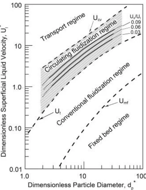
Figure 2.2.1 Liquid-solid fluidization regime map based on dimensionless particle diameter
and dimensionless superficial liquid velocity (J. Wang et al. 2019)
Many studies have focused on the flow regimes map of liquid-solid fluidized bed (Sang and Zhu
2012). With the development of liquid-solid circulating fluidized bed, the circulating fluidization
regime has been added and studied extensively. Long and Zhu have modified the calculation of
Ucv which is also extended to inverse liquid-solid circulating fluidization with low density
particles.
Hydrodynamics of LSCFB
Solids holdup distribution
Axial solids holdup in LSCFB has been reported by many researchers under a wide range of
superficial liquid velocities and solid circulation rates (Zheng et al. 1999; Sang and Zhu 2012).
non-uniformity has only been observed in steel shots particles with high particle terminal velocity under
relatively low superficial liquid velocity. The slow acceleration of the heavy particle accounts for
the non-uniform axial profile.
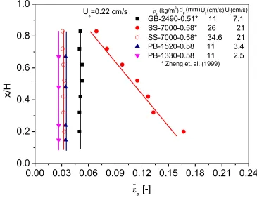
Figure 2.3.1 Axial solids holdup distribution in LSCFB at constant solid circulation rate for
different particles (Sang and Zhu 2012)
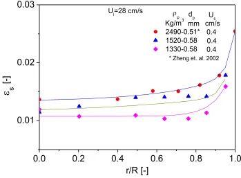
Radial solids holdup has also been studied by Liang, Sang and Zheng (Zheng et al. 2002; W.-G.
Liang et al. 1996; Sang and Zhu 2012). They have found that an increasing trend of solids holdup
from center to the wall measured by optical fiber probe. And the degree of non-uniformity is
increasing with solids circulation rates and decreasing with superficial liquid velocity. And the
particle properties will also affect the radial distribution.
0.00 0.03 0.06 0.09 0.12 0.15 0.18 0.21 0.24
0.0
0.2
0.4
0.6
0.8
1.0
GB-2490-0.51* 11 7.1 SS-7000-0.58* 26 21 PB-1520-0.58 11 3.4 PB-1330-0.58 11 2.5
x/H
s
[-]
Us=0.22 cm/s* Zheng et. al. (1999)
Ut(cm/s) p (kg/m3) d
p (mm)
Figure 2.3.2 Solids holdup radial distribution in LSCFB riser (Sang and Zhu 2012)
Onset velocity
Bed empty experiments were carried out in downer of inverse liquid-solid circulating fluidized
bed. The circulating fluidized bed is operating at steady state as solids are flowing downwards in
the downer, collected in the upcomer and been returned to the downer. The bed empty experiment
starts when solids feed was shut down while liquid flow was unchanged. The time was measured
for liquid flow to carry away all the particles in the solids till the fluidized bed is empty. For each
superficial liquid velocity, there is a corresponding bed empty time. Apparently, the bed empty
time is decreasing with superficial liquid velocity because solids travel faster under higher
superficial liquid velocities. And the change is more abrupt when the liquid velocity is relatively
low, and slope becomes less steep with the increase of liquid velocity.
The onset velocity of liquid-solid circulating fluidized bed is defined as the critical superficial
liquid velocity where a sudden change of bed empty time occurred. Below onset velocity, it takes
incredibly long time to empty the fluidized bed as the system is not in complete circulating regime.
0.0 0.2 0.4 0.6 0.8 1.0
0.01 0.02 0.03
2490-0.51* 1520-0.58 1330-0.58 * Zheng et. al. 2002
Ul=28 cm/s
r/R [-]
s
[-]
Kg/m3 mm
dp
p
0.4 0.4 0.4 cm/s
And beyond onset velocity, the system is under fully developed circulating regime where all
particles can be transported easily out of the column. (Zheng and Zhu 2001)
Pressure balance in LSCFB
Pressure balance in LSCFB is crucial in the design and operation of the circulating fluidized bed.
Particles in LSCFB are circulating between the two columns. Starting from the distributor,
particles are transported to the top by high velocity liquid and fall down to the downcomer by the
force of gravity. A packed bed or semi-fluidized bed is formed at the bottom of the downcomer,
and solids are gradually fed to the distributor in the riser through the feeding pipe with the help of
gravity. A steady and controllable circulation of solids is achieved by adjusting the pressure
difference between the bottom of the riser and the downcomer. The riser and the downcomer work
as a U-tube. The downcomer that contains more heavy solids will have higher pressure that
constantly push particles to the riser that has less pressure due to its less holding of solids. Solids
are packed from the bottom section of the downcomer to the feeding pipe before entering the riser.
When solids are packed, their weight are supported by the wall of the column, which inhibit the
pressure to be transferred, thus some liquid are injected to semi fluidized the particles in the
downcomer, so particles are loosened and the pressure from the particles are easier to be transferred
to the distributor region in the riser. The auxiliary flow distributor works as a non-mechanical
valve that controls the pressure drop from the packed solids to the riser which is used to adjust the
solid circulation rate. (Zheng and Zhu 2000)
Transition Regime
In Zheng’s study, the transition regime is mentioned when describing the operating window of
LSCFB. For a constant auxiliary flow rate, solids circulation rate is increasing with superficial
liquid velocity. Beyond a critical liquid velocity (turning point), solid circulation rate will reach
constant. Beyond the turning point, solids circulation rate is limited by the pressure drop between
the storage column and liquid flow distributor dictated by auxiliary flowrate. In other words, solid
circulation rate reaches maximum. Prior to reach the turning point, the pressure drop from the
storage column is not the limiting factor for solid circulation rate, which explains the increasing
Cluster in liquid-solid circulating fluidized bed
Liquid fluidization is often regarded as homogeneous fluidization. Very rare literature has
mentioned clusters in liquid-solid circulation fluidized bed operating under high superficial liquid
velocity. Chen and Fan have studied clusters in liquid-solid transport bed. The formation and
disintegration of clusters were captures in the 2D liquid-solid transport bed by PIV, where the
range of solids holdup is 0.056 to 0.028. Some captured cluster photos are presented in Figure
2.3.3. It is found that clusters formed in the vertical direction and will be rotated to a horizontal
alignment to gradually disperse. The studied cluster size was ranging from 2 to 7 particle
diameters. It is found that the degree of clustering is increasing with solids holdup and is also
dependent on Re. The probability of clusters and cluster characteristics were investigated followed
by the slip velocity of clusters which is found to be dependent on cluster size and cluster
arrangement. (Chen et al. 1991)
Clusters have also been studied in non-circulating liquid-solid fluidized bed where solids holdup
is ranging from 0.07 to 0.114. The cluster size and cluster number were found to be increasing
with solids holdup due to increased particle collision in dense condition as explained by the author.
And the overall clustering effects were quantified by box fractal dimension, a measure of
complexity of cluster images, which is believed to be a reflection of cluster coalescences and
large-scale clusters. (An, Liu, and Fu 2007)
Up to date, no researchers have given quantitative and systematic results on clusters in liquid
fluidized bed. Most results remain in qualitative description. And the cluster size, frequency of
cluster formation and disintegration, cluster arrangement and volume fraction of cluster etc. are
crucial effects of cluster on the flow behavior of solids. It is still unclear the impact of instantaneous
Figure 2.3.3 Typical Cluster in liquid-solid transport bed obtained from PIV with time
interval of 0.6s (Chen et al. 1991)
Hydrodynamics of Inverse Conventional fluidization
In most fluidization systems, heavy solids are fluidized by an upflow of liquid or gas. Whereas,
when the solids density is lower than the fluid, a downflow if liquid is required as particles are
floating at the top at its starting position, so called inverse fluidization. Due to the small inertia of
fluidization. Fan (Fan, Muroyama, and Chern 1982) is the first to report that bed expansion of
inverse fluidization didn’t follow the well-known Richard-Zaki equation, and the exponent n is
modified to better fit in prediction of voidage of inverse fluidization. Continuing Fan’s work,
Karamanev (Nikov and Karamanev 1991; Dewsbury, Karamanev, and Margaritis 2000; Dimitar
G. Karamanev and Nikolov 1992; D. G. Karamanev and Nikolov 1992) has found out the free
rising of low density particle doesn’t obey newton’s law. And the updated drag coefficient is
measured for many types of particle in a wide range of density and diameter, all in newton regime.
Based on the modified drag coefficient, revised particle terminal velocity can be calculated. And
the Richard-Zaki equation for upflow fluidization is found to be valid without changing exponent
n. Other hydrodynamics characteristics, such as minimum fluidization has been investigated as
well in the last few decades.
Inverse fluidized bed has been adopted as bioreactor for wastewater treatment (Buffière 2000)(D.
Wang et al. 2010; Nikolov and Karamanev 1987; Buffière and Moletta 1999). And the mass
transfer in inverse fluidization has been studied experimentally as well.
Behavior of low density particles in liquid
In circulating fluidized bed risers, the radial flow structure of solids has been studied extensively.
A core-annulus flow structure has been found, as dilute particles are carried by fast flowing fluid,
and a dense region near the wall is observed. In many cases, the flowing direction of wall region
is opposite to the direction of fluid flow in the core region due to insufficient drag force from the
hindered fluid velocity near the wall. Thus, the radial flow structure is governed by the drag force
in the streamline direction.
In liquid solid systems, lateral forces play significant roles in the migration of particles, which
result in a different radial flow structure. Since the net weight of particles is drastically reduced
due to the existence of liquid, the drag force required to fluidize the particles in lowered. The
hindered liquid velocity near the wall is more likely to provide sufficient drag force. (Carlo et al.
2009; Matas, Morris, and Guazzelli 2004)
Figure showing the radial solids holdup distribution of low density particles in the downer. We
dense region gradually disappears with increasing liquid velocity. And at high liquid velocity,
solids holdup is found to be lower in the wall region. This is because of lifting force push particles
against the wall. Lifting force can be expressed in the following equation.
At high liquid velocity, the velocity gradient near the wall region is high, which intensifies the
lateral movement of particle from the wall to the center.
The lifting force is a function of velocity gradient. A large velocity gradient will lead to a higher
lifting force. Based on the velocity profile of both laminar and turbulent flow, velocity gradient
increases from center to the wall in pressure induced pipe flow. In the center region, velocity
gradient diminished with increasing liquid velocity, when the flow is approaching turbulent flow
regime. In the wall region, the velocity gradient becomes more significant as the velocity change
from the center to the wall become abrupt. The features contribute to the particle radial flow
structure as well.(Han and Hunt 1995, 1994; Saffman 1965; GOTOH 1970)
Richardson-Zaki equation
JF Richardson etc. have done many studies on the sedimentation and fluidization of liquid-solid
system in the last century. The most notable results is Richardson and Zaki equation which dictate
the relationship of slip velocity and voidage in both sedimentation and fluidization processes. The
beauty of Richardson-Zaki equation is the simplicity of calculating voidage in the form of 𝑈𝑙 𝑈𝑡= 𝜀
𝑛
with n being a semi empirical value. Over the years, many studies have been focused on improving
the correlation of exponent n to provide a better prediction of voidage with different particle
properties and operating conditions. Khan and JF Richardson have demonstrated that n is ranging
from 2.4 and 4.8. Karamanev has proven that the same correlation from Khan can be applied to
inverse fluidization with low density particles that have to be fluidized downwardly. Many
correlations have been proposed for exponent n as a function of Re, Ar, d/D etc., and n is being
treated as an empirical parameter that can be helpful in providing a better fit. Countless data have
been fitted under various conditions and particle properties, which leave many the impression that
n is an empirical number. However, n is actually a theoretical parameter that can be derived from
In 1954, Richardson and Zaki have walked through the derivation process of drag force exerted on
the particle considering the effects of particle-particle interaction. Particles don’t interact with each
other directly, but the existence of other particles will shape the velocity profile/gradient around
each particle. Since the drag force is directly related to velocity gradient, effects of surround
particles can’t be ignored when studying the drag force on a single particle. Richardson and Zaki
derived the drag force equation assuming particle arrangement pattern under certain solids holdup
conditions, in order to solve the equation analytically. They were able to derive the drag force
equation for different solids holdup and two configurations of particle arrangements. First
configuration gives the most space for liquid flow, while the second configuration offers the
minimum space for liquid, under the same solids holdup condition.
From the derivation process, we can conclude what variables are included in exponent n: particle
and fluid properties such as densities, viscosities and particle diameter, particle-particle interaction
such as particle position arrangement.
Traditional method estimating exponent n using particle Reynolds number or Archimedes number
fail to consider particle arrangement. It is commonly believed, that particle arrangement is
consistent within one type of particle, so it can be a manifestation of particle properties.
Hydrodynamics of inverse three-phase fluidization
They hydrodynamics of inverse three-phase fluidized bed have also been studied before with the
application of low density particles. A typical flow regime map is shown in Figure 2.4.1 from
Buffie` re(Buffière and Moletta 1999). It has shown that the hydrodynamics is greatly affect by
the gas flow and liquid flow. The liquid flow is providing the drag force to fluidize the particles,
and the gas bubbles is going to change the liquid-solid mixture which helps to the floating solids
to move down. And many studies have reported on the study of relationship between gas holdups
Figure 2.4.1 Flow regime map for the inverse three-phase fluidized bed based on Ul and Ug.
(A) fixed or partially fluidized bed; (B) fluidized bed with dispersed bubbles; (C) fluidized
Nomenclature
Archimedes number defined by
Particle drag coefficient
Particle diameter (mm)
Column diameter (m)
Buoyancy, drag force and gravity
Solids circulation rate (kg/ (m2s))
Gravity acceleration
Reynolds number defined by
Particle terminal Reynolds number defined by
Auxiliary liquid velocity (cm/s)
Superficial liquid velocity (cm/s)
Superficial solids velocity (cm/s)
Slip velocity (cm/s)
Particle terminal velocity (cm/s)
Transition velocity demarcate the conventional particulate regime and
circulating fluidization regime (cm/s)
Local liquid velocity and local particle velocity (cm/s)
Average particle velocity (cm/s)
Ar d g3p (p− l) l/ l2
D C p d D , ,
b d g
F F F
s
G
g
Re U dl p l/ l
t
Re U dt p l/ l
Greek letters
Average bed voidage
Average solids holdup
Liquid viscosity (mPa∙s)
Particle density (kg/m3)
Subscripts
Liquid
Particle
s Solids
s
l
p
l
Reference
An, Xiaodong, Mingyan Liu, and Yunguan Fu. 2007. “Clustering Behavior of Solid Particles in
Two-Dimensional Liquid-Solid Fluidized-Beds.” China Particuology.
https://doi.org/10.1016/j.cpart.2007.07.001.
Bi, Hsiaotao, and Jingxu Zhu. 1993. “Static Instability Analysis of Circulating Fluidized Beds
and Concept of High-Density Risers.” AIChE Journal 39 (8): 1272–80.
https://doi.org/10.1002/aic.690390803.
Buffière, P. 2000. “The Inverse Turbulent Bed: A Novel Bioreactor for Anaerobic Treatment.”
Water Research 34 (2): 673–77. https://doi.org/10.1016/S0043-1354(99)00166-9.
Buffière, Pierre, and René Moletta. 1999. “Some Hydrodynamics Characteristics of Inverse
Three Phase Fluidized-Bed Reactors.” Chemical Engineering Science 54 (9): 1233–42.
https://doi.org/10.1016/S0009-2509(98)00436-9.
Carlo, Dino Di, Jon F Edd, Katherine J Humphry, Howard A Stone, and Mehmet Toner. 2009.
“Particle Segregation and Dynamics in Confined Flows.”
https://doi.org/10.1103/PhysRevLett.102.094503.
Chen, Ye Mon, Chien Sheng Jang, Ping Cai, and Liang Shih Fan. 1991. “On the Formation and
Disintegration of Particle Clusters in a Liquid-Solid Transport Bed.” Chemical Engineering
Science 46 (9): 2253–68. https://doi.org/10.1016/0009-2509(91)85124-G.
Dewsbury, K H, D G Karamanev, and A Margaritis. 2000. “Dynamic Behavior of Freely Rising
Buoyant Solid Spheres in Non‐Newtonian Liquids.” AIChE Journal 46 (1): 46–51.
Fan, Liang Shih, Katsuhiko Muroyama, and Song Hsing Chern. 1982. “Hydrodynamics
Characteristics of Inverse Fluidization in Liquid-Solid and Gas-Liquid-Solid Systems.” The
Chemical Engineering Journal 24 (2): 143–50. https://doi.org/10.1016/0300-9467(82)80029-4.
Han, Q., and J.D. Hunt. 1994. “Particle Pushing: The Attachment of Particles on the Solid-Liquid Interface during Fluid Flow.” Journal of Crystal Growth 140 (3–4): 406–13.
https://doi.org/10.1016/0022-0248(94)90317-4.
Han, Q., and J.D. Hunt. 1995. “Particle Pushing: Critical Flow Rate Required to Put Particles
into Motion.” Journal of Crystal Growth 152 (3): 221–27.
https://doi.org/10.1016/0022-0248(95)00085-2.
Karamanev, D. G., and L. N. Nikolov. 1992. “Bed Expansion of Liquid-Solid Inverse Fluidization.” AIChE Journal 38 (12): 1916–22. https://doi.org/10.1002/aic.690381208.
Karamanev, Dimitar G., and Ludmil N. Nikolov. 1992. “Free Rising Spheres Do Not Obey
Newton’s Law for Free Settling.” AIChE Journal 38 (11): 1843–46.
https://doi.org/10.1002/aic.690381116.
Liang, W.-G., J.-X. Zhu, Y. Jin, Z.-Q. Yu, Z.-W. Wang, and J. Zhou. 1996. “Radial
Nonuniformity of Flow Structure in a Liquid-Solid Circulating Fluidized Bed.” Chemical
Engineering Science 51 (10): 2001–10. https://doi.org/10.1016/0009-2509(96)00057-7.
Liang, Wugeng, Shuliang Zhang, Jing-Xu Zhu, Yong Jin, Zhiqing Yu, and Zhanwen Wang.
1997. “Flow Characteristics of the Liquid–Solid Circulating Fluidized Bed.” Powder Technology
90 (2): 95–102. https://doi.org/10.1016/S0032-5910(96)03198-1.
Matas, J P, J F Morris, and E Guazzelli. 2004. “Lateral Forces on a Sphere.” Oil & Gas Science
and Technology – Rev. IFP 59 (1): 59–70.
http://ogst.ifpenergiesnouvelles.fr/articles/ogst/pdf/2004/01/matas_vol59n1.pdf.
Nikolov, L., and D. Karamanev. 1987. “Experimental Study of the Inverse Fluidized Bed Biofilm Reactor.” The Canadian Journal of Chemical Engineering 65 (2): 214–17.
https://doi.org/10.1002/cjce.5450650204.
Nikov, I., and D. Karamanev. 1991. “Liquid‐solid Mass Transfer in Inverse Fluidized Bed.”
AIChE Journal 37 (5): 781–84. https://doi.org/10.1002/aic.690370515.
385–400. https://doi.org/10.1017/S0022112065000824.
Sang, Long, and Jesse Zhu. 2012. “Experimental Investigation of the Effects of Particle Properties on Solids Holdup in an LSCFB Riser.” Chemical Engineering Journal 197 (July):
322–29. https://doi.org/10.1016/J.CEJ.2012.05.048.
Wang, Ding, Trent Silbaugh, Robert Pfeffer, and Y.S. Lin. 2010. “Removal of Emulsified Oil from Water by Inverse Fluidization of Hydrophobic Aerogels.” Powder Technology 203 (2):
298–309. https://doi.org/10.1016/J.POWTEC.2010.05.021.
Wang, Jiaying, Yuanyuan Shao, Xilong Yan, and Jesse Zhu. 2019. “Review of
(Gas)-Liquid-Solid Circulating Fluidized Beds as Biochemical and Environmental Reactors.” Chemical
Engineering Journal, June, 121951. https://doi.org/10.1016/J.CEJ.2019.121951.
Zheng, Ying, and Jing-Xu (Jesse) Zhu. 2000. “Overall Pressure Balance and System Stability in
a Liquid–Solid Circulating Fluidized Bed.” Chemical Engineering Journal 79 (2): 145–53.
https://doi.org/10.1016/S1385-8947(00)00168-6.
Zheng, Ying, and Jing-Xu (Jesse) Zhu. 2001. “The Onset Velocity of a Liquid–Solid Circulating
Fluidized Bed.” Powder Technology 114 (1–3): 244–51.
https://doi.org/10.1016/S0032-5910(00)00318-1.
Zheng, Ying, Jing-Xu Zhu, Narenderpal S Marwaha, and Amarjeet S Bassi. 2002. “Radial Solids
Flow Structure in a Liquid–Solids Circulating Fluidized Bed.” Chemical Engineering Journal 88
(1–3): 141–50. https://doi.org/10.1016/S1385-8947(01)00294-7.
Zheng, Ying, Jing-Xu Zhu, Jianzhang Wen, Steve A. Martin, Amarjeet S. Bassi, and Argyrios
Margaritis. 1999. “The Axial Hydrodynamics Behavior in a Liquid-Solid Circulating Fluidized Bed.” The Canadian Journal of Chemical Engineering 77 (2): 284–90.
Chapter 3
3
Hydrodynamics of Inverse Liquid-Solid Circulating Fluidized
Bed
Abstract
Hydrodynamics of inverse liquid-solid circulating fluidized bed is experimentally studied with five
types of low density particles under a wide range of operating conditions. Solids holdup axial
distribution is found to be uniform. And radial solids holdup is found to be generally uniform with
occasional dilute region exist near the wall. The general trend of average solids holdup with
superficial liquid velocity and solids circulation rate is examined, and the effects of particle
properties are found to be not significant. The slip velocity calculated using measured solids
holdup is found to be uncommonly higher than particle terminal velocity using particles with small
particle Reynolds number. Modification is applied to Richardson-Zaki equation to account for
clustering effects in liquid-solid circulating fluidized bed.
Key words: liquid-solid fluidization, solids holdup, circulating fluidized bed, inverse fluidization,
slip velocity, Richardson-Zaki equation
Introduction
A typical upward circulating fluidized bed has two columns, a riser fluidized bed and a downer
fluidized bed. The riser operates at high liquid velocity to transport particles upwards and can
provide high contact efficiency and high mass and heat transfer rate (Zhu et al. 2000). The downer,
usually in large diameter, operates in less liquid velocity that offers longer residence time
compared with the riser. The two distinct operating zones allows continuous operation of solids
and large throughput of liquid. Because of the above advantages, liquid-solid circulating fluidized
bed has drawn many attentions in chemical, biochemical, food and pharmaceutical industries. It
has demonstrated promising potential in wastewater treatment (Nelson, Nakhla, and Zhu 2017; A.
Patel, Zhu, and Nakhla 2006; Eldyasti et al. 2010), iron-exchange and lactic acid production
processes (M. Patel et al. 2008) The riser usually take advantage of the short residence time of
liquid and solid for better contact. For example, in iron-exchange process (M. Patel et al. 2008;