Available Online atwww.ijcsmc.com
International Journal of Computer Science and Mobile Computing
A Monthly Journal of Computer Science and Information Technology
ISSN 2320–088X
IMPACT FACTOR: 6.017
IJCSMC, Vol. 5, Issue. 9, September 2016, pg.216 – 221
DEVELOPMENT OF FPGA BASED REMOTE
CONTROLLED POWER STEERING
CONTROL SYSTEM FOR VEHICLES
Mrs. Pawar Vaishali Manohar
1, Dr. Gaikwad P. K
2, Dr. Shinde S.A
31,2,3 Department of Electronics,
Shivaji University, Kolhapur (M.S.), INDIA,
Abstract
The project work is for designing and development of a prototype system for driving automobile vehicle's Power Steering using Cellular Phones. The smart steering control system implemented here does not only controls the steering angle, but it also provides the facility of moving the complete wheel system to mobilize the vehicle in four directions on horizontal plane. This type of vehicle movement makes it convenient to park the vehicle in a small parking area. The Xilinx FPGA based system comprises of a Soft IP Core implementation using Finite State Machine (FSM); based on Very High Speed Integrated Circuit Hardware Description Language (VHDL). To control steering movements with different directions, the cellular phone keys have to be dialled, so that at the receiving end, the Dual Tone Multiple Frequency (DTMF) decoder would generate related binary data. The Xilinx Virtex-5 Field Programmable Gate Array (FPGA) board from Digilent Inc. was deployed for the hardware realization. The system developed here inputs the binary data from DTMF device and fed it to the FPGA to move the stepper motor (being coupled to the vehicle steering) in a desired direction. The Xilinx ISE (14.6 Version) platform was used for realization of the system.
Keywords: Smart Car Parking, DTMF, FSM, FPGA, Steering Control
1. Introduction
(EPCU). The Free scale microcontroller MC9S12DG128 base smart car steering control system is also reported in [2].
The United State (US) patent [3] shows that, dynamic control systems for automotive vehicles have recently begun to be offered on various products. Dynamic control systems typically control the yaw of the vehicle by controlling the braking effort at the various wheels of the vehicle. Yaw control systems typically compare the desired direction of the vehicle based upon the steering wheel angle and the direction of travel. By regulating the amount of braking at each corner of the vehicle, the desired direction of travel may be maintained. Typically, the dynamic control systems do not address roll of the vehicle. For high profile vehicles in particular, it would be desirable to control the roll over characteristic of the vehicle to maintain the vehicle position with respect to the road. That is, it is desirable to maintain contact of each of the four tires of the vehicle on the road
2. Design Flow
The reconfigurable device Field Programmable Gate Array (FPGA) from Xilinx Inc. was hardwired to accept the information generated from the Dual Tone Multiple Frequency (DTMF) device. The DTMF is a term which is used in telephone industry. When any key on telephone or mobile phone is pressed, a particular tone is generated and which is audible; which is nothing but a DTMF tone. The application of Integrated Circuit (IC) MT8870 DTMF decoder IC is to decode DTMF tone from mobile phone[4]. It generates a four bit binary code associated with the key pressed on the mobile or telephone device. The Soft Intellectual Property (IP) core designed in this research work was implemented on the Xilinx FPGA. The Finite State Machine (FSM) based hardware design process was used to rotate the steering-controlling stepper motor in an appropriate direction. The figure 1 shows a flow diagram, it reveals the technique to accept the signals from DTMF device and move the car steering in a desired direction. It shows that, when steering control signal is asserted high, the direction control signal is entertained to decide the steering direction.
Figure 1: Flow diagram to control the steering direction as steering enable signal is asserted high
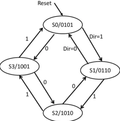
Figure 2: Finite State Machine for Stepper Motor Driver
The technology platform to design and develop prototype for remote controlled smart car-steering control was developed.
Figure 3: Block diagram of FPGA based Remote Controlled Power Steering Control System for Vehicle
The figure 3 shows a block diagram of FPGA based Remote Controlled Power Steering Control System for Vehicle. The transmitter mobile sends the audio frequency signals when a particular key is dialled on its keypad. The cellular phone is embedded with DTMF keypad. At the receiving end, the decoder IC M-8870 identifies the DTMF tones, as given in [6]. It generates a four bit digital data (Q1, Q2, Q3 and Q4) associated to the key pressed on the keypad at the transmitting end. This binary data was fed at the input of FPGA lines. The Least Significant Bit (LSB) Q1 was used to control the direction of stepper motor in either forward or reverse direction. However, the bit Q4 (from DTMF IC) was connected to FPGA line, to enable the finite state machine process; implemented in the same reconfigurable device. The DTMF output (Q1) would be entertained for controlling the direction of stepper motor when the bit Q4 is asserted high. The shaft of the motor would be further connected to the power steering; hosted in a car system.
The VHDL entity of the entire soft IP core is given here. It shows that there are four input signals and one 4-bit output vector signal. The function of each input and output lines is explained in the simulation and synthesis part of this paper.
motor : out STD_LOGIC_VECTOR (3 downto 0)); endstpr;
The partial architecture body of the module is also given to show the process with finite state machine. process(reset,steper_clk_1k,dir)
begin
if(reset='1')then state<= s0; motor<="0101";
elsifrising_edge(steper_clk_1k)and (steering= '1') then case state is
when s0 => if dir='1' then state<=s1; motor<=X"6"; elsif(dir='0')then
state<=s3; motor<=X"9"; end if;
……… ………
end case; end process;
The process code shows that, when „reset‟ signal is „1‟ the entire finite state machine (FSM) is reset to state s0 and „motor‟ signal is initialised with “0101”. On the other hand, when „reset‟ signal is not activated, the rising edge of the input clock is taken into consideration to travel the FSM in next states and produce necessary output signals. To control the state machine flow, the clock signal is also logically ANDed with the input signal „steering control‟. That means to move the FSM in next states the rising edge of clock is not sufficient; also the steering signal must be asserted to high. To drive the stepper motor stepwise, the FPGA provides necessary signals in each state. That is, during state s0, “0101”or X“5”, during state s1, “0110” or X “6” as shown in the simulation window of Xilinx ISE simulation tool, figure 4.
3. Simulation and Synthesis Results:
The Soft IP core based on Very High Speed Integrated Circuit Hardware Description Language (VHDL) was developed to realise the process shown in the figure 2. The VHDL code was simulated using Xilinx ISE (30 Days Evaluation Version 14.6) which includes simulation tool ISim. The figure 3 shows the simulation results with necessary input/output signals of the VHDL entity.
Figure 4: Simulation Results for Vehicle Steering Control Mechanism driving Stepper Motor
state machine takes its transition in reverse direction when the said signal is pulled down. The possibility of moving the FSM in either forward or reverse direction is controlled by external signal „dir‟; only when additional signal „steering‟ is enabled. The FSM stays to its present state when control signal „steering‟ is disabled.
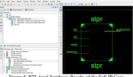
Figure 5: RTL level Synthesis Results of the Soft IP Core
The figure 5 illustrates the synthesis results of the top level VHDL module obtained by Xilinx ISE Synthesis Tool. The left top corner of Figure 5 shows the Design window of the Xilinx ISE platform. The Process window at the left bottom of the same screenshot shows that the top level module (stpr) was successfully synthesized as well as implemented as per the design flow. On the right pane of the Figure 5 it shows the Register Transfer Level (RTL) level synthesis result of the design. The master clock signal referred to as „clk‟, global reset, „reset‟, direction control signal „dir‟ and steering enable signal „steering‟ are shown at the input side of the top level VHDL entity. On the other side of the same module, a four bit vector signal („motor‟) is also shown in figure 5. At the hardware level, this signal was fed to the input of stepper motor driver card. In this soft IP core development, there is an instantiated component named as „ClkDivMain‟, instantiated with two instance names u1 and u2. The FPGA board „Genesys‟, provided from Digilent Inc. has on board clock source of 100MHz. The clock divider module [5], instantiated in the top level entity divides the 100MHz clock signal and produces the necessary timing signal to drive the state machine with appropriate speed. Finally, the stepper motor was driven with the speed of the clock signal produced in this way.
4. Hardware Implementation of the System:
The four bit signal 'motor [3:0]', routed towards the Pmod connector (JA) is also shown in Figure 6. To hold the 4 bit data generated from FPGA lines, a latch IC 74244 was embedded on the stepper motor driver card. The stepper motor coils were driven through current buffer IC ULN2003.
5. Conclusion
This research work deals with design and development of a prototype for driving the vehicle's power steering using cellular phones located remotely. The FPGA based system comprises of a soft IP core implementation using Finite State Machine (FSM) based VHDL design methodology. To control steering movements with its direction, the cellular phone keys have to be dialled. The future plan of our work is to serve a new idea for automobile industry that would couple the stepper motor with four wheels simultaneously. This would help the vehicle to park it easily in a small parking area as well.
References:
[1] V.Venkateswaran, N.Prakash, "INTELLIGENT APPROACH FOR SMART CAR PARKING RESERVATION AND SECURITY MAINTENANCE SYSTEM", IJRET: International Journal of Research in Engineering and Technology eISSN: 2319-1163 | pISSN: 2321-7308, Volume: 03 Issue: 02 | Feb-2014, pp. 248-251
[2] Xiao Wang, Hua Li; Yuan Zhu, "Design on automatic control system for smart car based on μC/OS-II", Cloud Computing and Intelligent Systems (CCIS), 2012 IEEE 2nd International Conference on Volume:03, ISBN:978-1-4673-1855-6, pp. 1188-1191
[3] Jianbo Lu, Todd Allen Brown, "Rollover stability control for an automotive vehicle using rear wheel steering and brake control", US 6799092 B2, Sep 28, 2004
[4] Application note, viewed 7 January 2016 from http://worldofmcu.com/2012/12/dual-tone-multiple-frequency-dtmf.html
[5] Support Document, “Xilinx ISE demo project for the PmodAD2 and a PmodDA1”, Digilent, Inc., Pullman, WA 99163-0428, November 2011, DSD-0000321 viewed 8 January 2016 from https://www.digilentinc.com/Products/Detail.cfm?NavPath=2,401,933&Prod=PMOD-AD2
[6] JaseemVp, “DTMF (Dual Tone Multi Frequency) decoder Circuit schematic using M8870”,Circuits Gallery, viewed 9 January 2016 from http://www.circuitsgallery.com/2012/07/dtmf-dual-tone-multi-frequency-decoder-circuit-schematic-using-m8870-ic2.html
1
V. M. Pawar –. Mrs.Vaishali Manohar Pawar, born in INDIA, on May 21st, 1983, is M.Sc.-Electronics, fromDepartment
of Electronics, Shivaji University Kolhapur(2016), Diploma in Industrial Electronics(2002), M.S.B.T.E. Board, Pune,
April- (2002).
2
P. K. Gaikwad – Dr. Pawan K. Gaikwad, born in INDIA, on August 29th, 1976, is M.Sc.-Electronic Science, from Department of Electronic Science, Savitribai Phule Pune University Pune (1999), Ph.D. in Electronics(2010), Diploma in VLSI Design, Pune(2000). He is a Research Guide in Electronics for the faculty of Science in Shivaji University, Kolhapur (Maharashtra), INDIA. Under his guidance one student has been awarded for the degree of Ph.D.
3