18th International Conference on Structural Mechanics in Reactor Technology (SMiRT 18) Beijing, China, August 7-12, 2005 SMiRT18- J06-8
ANALYSIS OF REACTOR BODY FOR DROPPING OF FUEL FLASK
József GYÖRGYI*
Department of Structural Mechanics,
Budapest University of Technology and
Economics, M
ű
egyetem rkp. 3,
Budapest,
1
52
1
, Hungary
Phone: 36-1-463-1432, Fax: 36-1-463-1099
E-mail: [email protected]
Zoltán ZSIDI
TH-CAD Computing LTD, Szt. István tér
1
4,
Szeged, 672
1
, Hungary
Tamás EÖTTEVÉNYI
Power Stations and Network Engineering Company (ETV-ER
Ő
TERV), Angyal u.
1
-3,
Budapest,
1
094, Hungary
ABSTRACT
In the Hungarian Nuclear Power Plant was a project to put the fuel flask onto a special structure in the upper part of the reinforced reactor body. The structure was built form steel elements, and the fuel flask was support in four points on the structure. During the analysis we calculated the dynamic effect from the lifting procedure and the effect of earthquake too. After the discussion the power plant asked to analyse an accident situation, when the flask fall down form the middle level structure into the steel reactor container. The question was the calculation of displacements and stresses in these structures. For the calculation we used the finite element methods. The steel support structure has shell elements in the mechanical model and the reinforced walls, columns and slabs were modelling by solid elements. First step we calculated the natural circular frequencies of the mechanical model of the reactor structure. From the modal analysis we could decide the necessary numerical integration steps. The steel support structure was in plastic state, but was not broken. The reinforce walls and slabs were staying in elastic state and the stresses were under the limit.
Keywords: dropping body effect, non-linear dynamic calculation.
1. INTRODUCTION
The safety enhancement measures of the Paks Nuclear Power Plant (Hungary) requires the investigation of the influences of several accidental situations on the load bearing capacity of the NPP building structures. One of these accidental situations is the impact (drop) of the different heavy equipment (such as spent fuel transport flask) on the existing reinforced concrete slabs and walls of the reactor building during transportation. In last years we analysed of the transporting of the flask above the flask of the hermetic slabs (Györgyi, Lenkei, 2000 and Lenkei, Györgyi, 2002).
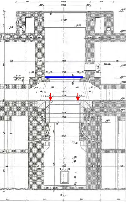
In this paper first we show the analysis of putting the fuel flask onto a special structure in the upper part of the reinforced reactor body. In Fig. 1 is a cross section of the reactor structure and the blue line shows the place of the support structure. The structure was built form steel elements, and the fuel flask was support in four points on the support structure. During the analysis we calculated the dynamic effect from the lifting procedure and the effect of earthquake too.
The container can be see on the Fig. 2.
Fig.2
The C 30 type container.
After the discussion the power plant asked to analyse an accident situation, when the flask fall down form the middle level structure into the steel reactor vessel. In case the large dynamic force loads of the steel support structure of reactor vessel. The place of the dynamic forces can be shown with red colour in the Fig. 1. In this case very large impact forces will be given for the steel support structure and from that the reinforced reactor walls. The question was the calculation of displacements and stresses in these structures. First step we calculated the natural circular frequencies of the mechanical model of the reactor structure. From the modal analysis we could decide the necessary numerical integration steps. Two loading cases were analysed. In the first case the maximum of the force was larger, but the impact time was less then the other case. In both cases the maximum of the dynamic forces were larger then the limit force of the support structure in statically case. During the analysis we used the regulations of NUREG 0612 [3].
2. CALCULATION OF SUPPORT STELL STRUCTURE
2.1. Statical calculation
The finite element model of the structure is on the Fig. 3.For calculation we use the COSMOS/M version 2.5 computer program [4].
The weight of the container was 850 kN, and the weight of the lifting structures was 280 kN. During the calculation from the ASME NOG-1-19989 regulation [5] we used 1.15 factor for calculation of the internal forces.
The own weigh of the structure was 62,7 kN. The material property of the steel: E = 2,0×10¹¹ Pa,
28 , 0
=
υ . The deformations form the statical loads are shown by Fig. 4.
Fig. 4
Displacements of support steel structure from statical loads
The Von-Mises reduced stresses can be seen on the Fig. 5. The maximal value of the stresses is 33,7 MPa.
Fig. 5
Von-Mises stress of support steel structure from the statical loads
The yield stress of the material: RTp0.2 =205MPa, the ultimate tensile stress:RmT =500MPa. Using the ANSI
N14.6 4.2.3 regulation [6], the allowable reduced stress is:
[ ]
34,2MPa 1500 ; 6 205
min =
=
σ .
2.2 Dynamic effect form dropping the fuel flask onto the structure
From the velocities we can calculate the equivalent dropping highs using the g 2
2 v
h= formula.
mm 0884 , 0 81 , 9 2 ) 60 / 5 , 2 ( g 2 2 2
1= = ⋅ = v
h , 0,000884mm
81 , 9 2 ) 60 / 25 , 0 ( g 2 2 2
2= = ⋅ = v
h .
The formula for calculation of the dynamic factors:
+ + + = 1 0 1 1 2 1 1 G G e h st µ ,
where G0 is the weight of the support structure, and G1 is the weight of the dropping body. In our cases:
26 , 2 850 7 , 62 1 1 269 , 0 0844 , 0 2 1 1 1 = + ⋅ + + =
µ , 2,00
850 7 , 62 1 1 269 , 0 000844 , 0 2 1 1 2 = + ⋅ + + = µ .
The maximal value of the stresses is 57,6 MPa. In case of extraordinary situation the allowable stress for tension
is0,9RTp0.2 =184MPaand for shear is0,5RTp0.2 =102MPa. Our structure is suitable in case of dropping
situation.
2.3 Earthquake analysis
The position of the container on the support structure is shown on Fig. 6.
During the analysis the container was modelling with rigid beam elements. At the mass point we calculate the inertial moments of the container too. The mass of the container was 85 t, and the inertial moments were IX = 0.174072E+06, IY = 0.174072E+06, IZ = 0.588241E+05 tm2. The height of the weight point in the mass was 0.156355 m under the upper level of the structure. The model for the earthquake calculation is on the Fig. 7. The designer acceleration response spectra at the support points of the structure was given form the complex earthquake analysis of the main building complex of the power plant (Fig. 8).
Fig. 7
The earthquake analysis model of the container
Fig. 8
Acceleration response spectra at the level of support structure [m/s
2]
Fig. 9
Vibration modes of the support structure with container
horizontal
vertical
During the calculation we used the modal analysis and calculated the first 15 frequencies of the system. The first frequency was 21.2 Hz and the last calculated frequency was 387 Hz. Some vibration mode is shown in Fig 9. We can see that our dynamic system was very rigid and the value of the acceleration response spectra for all modes was the zero period acceleration value. Therefore the maximum of stresses from the earthquake effect showing in Fig. 10 was only 67,7 MPa. It is less than the allowable stress in case of the extraordinary situation.
Fig. 10
Von-Mises stress of support steel structure from the earthquake
3.
MECHANICAL MODEL FOR ANALYSIS OF DROPPING EFFECT INTO THE
REACTOR VESSEL
3.1 The mechanical model of the structure
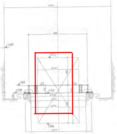
On Fig. 11 we can see some typical cross-sections of the reactor with the neighbour walls.
The model of the bottom part is a cylinder supported by two plates. At the top of this model there is a steel support structure. (Fig.12).
Fig. 12
The bottom parts of the reactor model
The middle part of structure is supporting the upper part. In it there are for columns changing cross-section and a vertical wall part, which is the wall of the spent fuel pool. We can see them in the middle of Fig. 11. The sizes of the different kind of elements are on Fig. 13.
Fig. 13
The middle parts of the reactor model
The upper part of the rector is a cylinder too, the thick of the wall neighbour of the storage pond is changing. In the wall of the spent fuel pool is a lock, which has the different stiffness in the model. The cylinder in the model is supported vertically by walls of the spent fuel pool and horizontally by a slab plate. The displacements of the boundary of the walls can be only vertical direction. But is not motion during the boundary of the plate. For the calculation of stresses we used the finite element methods. In the finite element model in the walls we used the solid and in the steel structure and in the plates we used the shell elements. The finite element model can be see on Fig 14.
7.82
-6.50 5.3
-0.5
Steelstructure
1.80 2.50 1.55
2.83 0.9 1.00
1.10 2.50
0.70 0.70
Fig. 14
Finite element model of the analysed structure
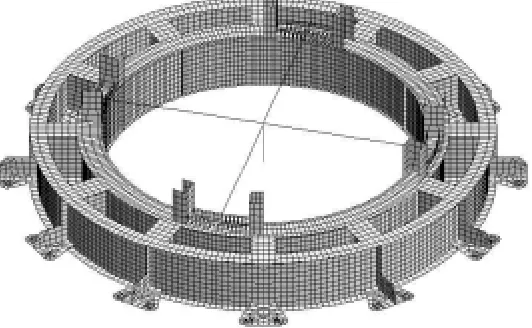
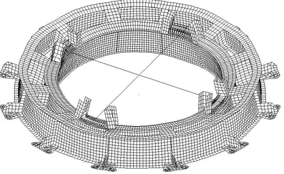
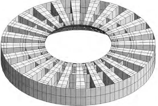
The reaction forces of the steel reactor vessel are the loads of the steel support structure. The steel structure has 24 beams but between the beams is contact by plate rings We can see the finite element model of the supporting structure on Fig. 15. In the model at the end of the beams was the additional mass points calculated form the reaction forces. The masses were put to the end of the each beam for some points. The number of the concentrated mass points was 216 and on the one point was 3378-kg mass.
3.2 The material properties
For linear analysis:Steel: E = 2,05×10¹¹ Pa,
ν
= 0,28,ρ
= 7800 kg/m3. Concrete: E = 2,156×1010 Pa,ν
= 0,167,ρ
= 2600 kg/m3.During the non-linear analysis the dates of the Huber-von Mises bilinear material model in case of S235JRG2 type steel:
The yield stress: Rp0,2 = 225 MPa.
The ultimate tensile stress: Rm = 370 MPa.
Allowable strain: εu = 26 %.
Fig. 16
Bilinear material model
The modulus at the second part of the diagram Et is:
100 [%] 2 , 0 [%] u 2 , 0 p m t − − = ε R R
E . In this case Et =5,62⋅108Pa.
3.3 The loads
The statical loads were calculated automatically from the geometry of the model. The concentrated forces, the reaction forces of the steel reactor vessel (sum of forces was 7157 kN) were put to the steel structure. For the calculation if common effect of statical and dynamic loads the statical load was put onto the structure than load changing in time. The time period for increasing the load to the given value is 10 s.
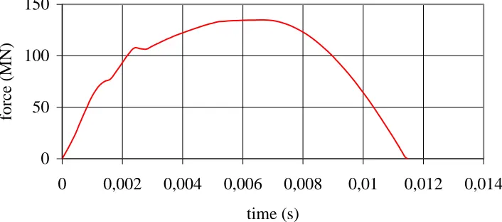
We have two type of dynamic force. In the first case the reactor vessel is not broken after dropping of the container and the force vector has the continuous function (Fig.17). The period of the effect of force is 0,0115 s and the maximum of the dynamic force is 134 MN.
0
50
100
150
0
0,002
0,004
0,006
0,008
0,01
0,012
0,014
time (s)
force (MN)
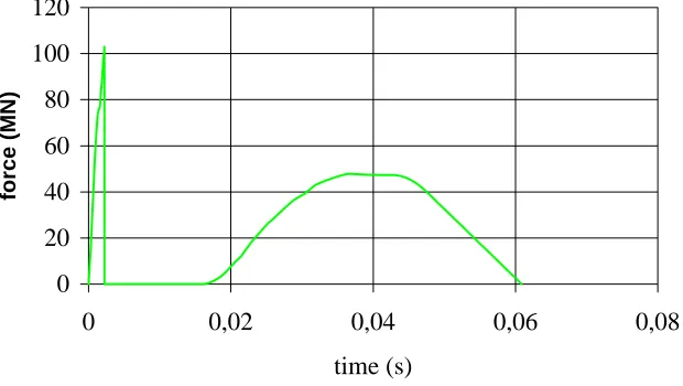
In the second case the steel reactor vessel is broken after dropping of the container in it and the force vector has two parts (Fig. 18). The first part period the maximum of the force is 103 MN but the time period is very small (0,002238 s). At the second part the period is long (0,01624 s - 0,0686 s) and at the slower force value (47,82 MN) the dynamic effect can be large. The dynamic effect depends from the ratio of the time period and of the force and natural period of the structure.
0
20
40
60
80
100
120
0
0,02
0,04
0,06
0,08
time (s)
force (MN)
Fig. 18
The dynamic load if the steel reactor vessel is broken
4. DYNAMIC CALCULATION
4.1 Calculation of natural frequencies
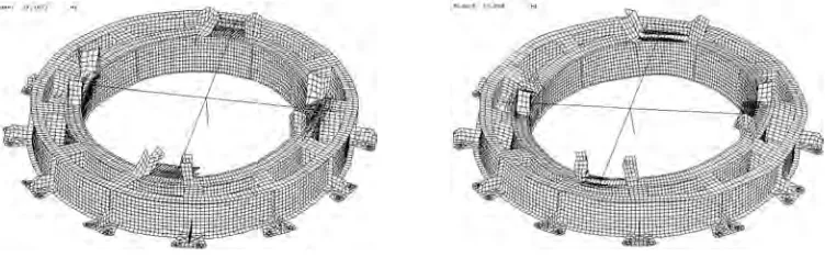
The first natural frequency of the system was 17.9 Hz and the period is 0.056 s. The part of the most important vibration form for the steel structure is in the Fig. 19. The natural frequency in this case was 18.8 Hz. The deformation of the steel structure in this case is shown in Fig. 20. The 20-th natural frequency is 26.9 Hz and the period is 0.037 s. We can see that the time period of the load in the first accidental situation is less, but at the second is more than the vibration period of the structure
Fig. 20
The vibration form of the steel structure at the third frequency
4.2 Calculation of displacements if the steel reactor vessel is no broken
The dynamic effect is beginning at 10.0 s time point, after the 10-s long statical force. The initial value of the displacement from the statical force is 0,8 mm. During the numerical integration the time step was 0.0001s. We calculated the displacements and internal forces in 500 time steps. The maximum of the vertical displacement was calculated in 0.014 s time point, and its value was 5.4 mm. The summarised displacement of the end of the beams from the statical and dynamical forces is shown by Fig. 21.
Fig. 21
Displacements if the steel reactor vessel is not broken
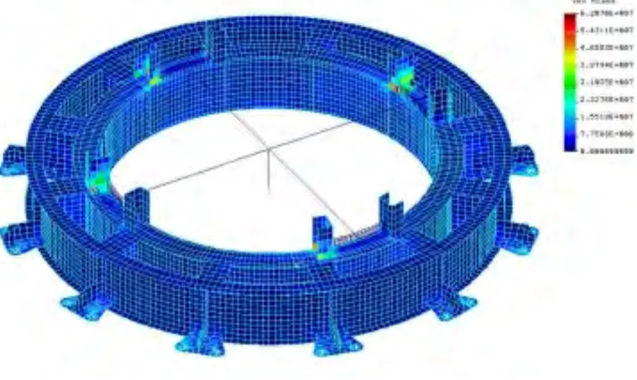
The Fig. 22 shows the stresses in the shell elements of the steel structure. The maximal value of the stresses is 264 MPa, which more then the yield stress, but less then the ultimate tensile stress. The element coloured by red are in plastic state.
In the concrete elements the stresses form the statical load and the dynamic effect are pressure generally. At the Fig. 23 we can see the stresses in the concrete elements. The maximum of tension stress is 10,3 MPa and the maximum of pressure stress is 25.9 MPa.
Fig. 23 Stresses of concrete structure from linear analysis if the steel reactor vessel is not
broken
4.3 Calculation of displacements if the steel reactor vessel is broken
The maximum of the vertical displacement was calculated in 0.05 s time point, and its value was 4.1mm. It is less then was in the previous case. The summarised displacement of the end of the beams from the statical and dynamical forces is shown by Fig. 24.
Fig. 24
Displacements if the steel reactor vessel is broken
The Fig. 25 shows the stresses in the shell elements of the steel structure. The maximal value of the stresses is 234 MPa, which more then the yield stress, but less then the ultimate tensile stress. The stresses in steel structure are less, than were in the case when the reactor vessel is not broken. The element coloured by red are in plastic state.
In the concrete elements the stresses form the statical load and the dynamic effect are pressure generally in this case two. At the Fig. 26 we can see the stresses in the concrete elements. The maximum of tension stress is 7,3 MPa and the maximum of pressure stress is 28.6 MPa. The tension stresses in the concrete structure in this case less, than was when the reactor vessel is not broken.
Fig. 25
Stresses of steel structure from bilinear analysis if the steel reactor vessel is broken
5. CONCLUSIONS
In the Hungarian Nuclear Power Plant was a project to put the fuel flask onto a special structure in the upper part of the reinforced reactor body. During the analysis we calculated the dynamic effect from the lifting procedure and the effect of earthquake too. The weight of the C-30 flask was 850 KN. The lifting velocity of the flask in normal case was 0.25 m/min and in no normal case it was 2,5 m/min. After the dynamic calculation we have got the dynamic coefficients, which were 2.0 and 2.28. The designer acceleration response spectra at the support points of the structure was given form the complex earthquake analysis of the main building complex of the power plant.
After that we analysed an accident situation, when the flask fall down form the middle level structure into the steel reactor vessel. In this case very large impact forces will be given for the steel support structure and from that the reinforced reactor walls. Two loading cases were analysed. In the first case the maximum of the force was larger, but the impact time was less then the other case. In both cases the maximum of the dynamic forces were larger then the limit force of the support structure in statically case.During the non-linear analysis we used the Huber-von Mises bilinear material model. The steel support structure was in plastic state, but was not broken. The reinforce walls and slabs were staying in elastic state and the stresses were under the limit.
ACKNOWLEDGEMENT
The authors are indebted to the Paks Nuclear Power Plant (PARt) and to the Hungarian Science Foundation (OTKA No. T 029635) for financing the work reported.
REFERENCES
[1] J. Györgyi, P. Lenkei, (2000), Proceeding of International Conference on Structures Under Shock and Impact, Cambridge, pp. 57-66.
[2] P. Lenkei, J. Györgyi, (2002), Proceeding of International Conference on New Trends in Statics and Dynamics of Buildings, Bratislava, pp. 197-200
[3] NUREG-0612, (1980), Control of Heavy Loads at Nuclear Power Plants solution of Generic Technical Activity A-36, Office of Nuclear Reactor Regulation, Washington
[4] COSMOS/M version 2.7, Advanced Modules (Volume 4). (2002) Structural Research and Analysis Corporation, Santa Monica, California, 2000.
[5] ASME NOG-1-1993, An American National Standard, Rules for Construction of Overhead and Gantry Cranes (top Running Bridge, Multiple Girder), The American Society of Mechanical Engineers, New York [6] ANSI N14.6-1993, American National Standards for Radioactive Materials - Special Lifting Devices for