Crack Opening Behavior of Penetrated Crack under Cyclic or Monotonic
Loading
Yeon Sik Yoo °, Seok Hwan Ahn 2), Ki Woo Nam 2) and Kotijo Ando 1)
1) Faculty of Engineering, Yokohama National University, 79-1, Tokiwadai, Hodogayagu,Yokoham, 240, Japan 2) Faculty of Engineering, Pukyong National University, 100, Yongdang-dong, Nam-ku, Pusan, 608-739, Korea
ABSTRACT
Crack opening displacements were examined experimentally at room temperature for both plate and pipe specimen containing a surface crack. Application of crack opening displacement solutions fi'om plate specimens, as proposed by the present authors, to pipe specimens were investigated. Crack opening displacement after penetration could be satisfactorily determined regardless of a type of load using the COD solutions proposed by the authors.
INTRODUCTION
The Leak Before Break (LBB) design philosophy used for high-pressure vessels and energy-related engineering plant equipment has recently been attracting much interest from a safety and economic point of view. The LBB concept is a design philosophy to guarantee that unstable fracture does not occur before a crack penetrates the wall thickness and even after complete penetration for a certain period. Moreover, it is judged that the acceptable LBB case can be made if the leakage is detectable before the crack length reaches a critical length. Studies on unstable fracture due to a crack and the evaluation of the crack opening displacement or crack opening area for leakage inspection of a structure under a monotonic and a cyclic load have been performed for various aspects. The most important steps which should be investigated in a LBB design can be summarized as follows [ 1 ]: (a) Throughout the life, a crack should not occur. (b) If a crack occurs, the crack propagation should be small and should be detectable in order to be repaired during regular inspection. (c) If a crack occurs and penetrates the structural parts, the crack propagation and the leakage should be as small as possible. Studies of LBB designs have been performed on various aspects of steps (a) and (b) above. There have also been some studies on step (c) and some useful knowledge about the effects of surface cracks has been reported. The present authors have reported [2] an investigation on the LBB condition and the crack opening behavior under a high fatigue stress. Studies on the crack opening displacement atter penetration in a plate and pipe, however, are relatively rare.
The aim of the present study is to investigate the basic behaviors of crack opening displacement (COD) atter crack penetration in a plate and a pipe. Basically, three main tasks have been identified. Task 1 was dealt with COD at a plate specimen with surface crack under cyclic loads and Task 2 considers COD when there is a inner and outer surface crack at a pipe specimen under cyclic loads. Task 3 is aimed to evaluate COD of ductile tearing.
CRACK OPENING DISPLACEMENT OF PENETRATED FATIGUE CRACK Plate subjected to cyclic tensile stress
In order to accurately estimate the characteristics of leak before break under cyclic load, it is a very important to evaluate precisely the crack growth and penetration behavior. The photographs of fatigue fracture surfaces obtained from the plate spechnens of 3%NiCrMo steel with surface crack are shown in Fig. 1 [ 1-3]. Fig.1 (a) shows the result from the small plate specimen under combined tensile and bending stress with a 80 mm width and 10 mm thickness. Fig.1 (b) and (c) the results obtained from the stress concentration specimens with a 80 mm width and 10 mm thickness. From these figures, it can be seen that the fatigue crack shapes have almost semicircular.
Stress intensity factor is very important paran~eter for evaluation the crack growth and penetration behaviors under cycle load in the case of plate with a surface crack. Newman-Raju's formula has been generally applied to analyze the stress intensity factor before crack penetration. The stress intensity factors K°s and K% at points S and B(see Fig.2) after penetration, as proposed by the present authors[2], are
K% = 8(a~)/8(a,) o(na,) °5 F(rl,) (1)
K~ = 5(a=)/5(ab) o(~ab) °s F01b)
(2)
SMiRT 16, Washington DC, August 2001 Paper # 1585
where as and a b are the crack length at the from surface and the back surface, respectively, and a e - 0.5 (3a s 2 -]- ab2) 0"5, 1"Is = a JW, rib = a b/W, and
F(rl) = (1- 0.51"1 + 0.371"12- 0.044113) / { 1- ri}0s
(3)
The terms 6(a) in the equations indicate the crack opening displacements and are expressed in the form
~5(a) = 4oa(1 - v 2) / EV(ri) (4)
where v is Poisson's ratio, E is Young's modulus, and
V(rl) = -0.071 - 0.5351"1 + 0.1691"12 + 0.0201"13 - 1.071(1/ri)log(1-rl)
(5)
When deriving Eqs. (1) and (2), three assumptions were made[2]"
1) The crack after penetration is assumed to retain its semi-elliptical shape, and as is assumed to be the major axis of the ellipse. The crack length ae at the center of the plate thickness can, therefore, be expressed as
ae = 0.5 (3a s 2 + abE) °5 (6)
2) The crack opening displacement in the center of the crack after penetration (on the line XX' in Fig.2(a)) is assumed to be the same on the front surface and the back surface.
3) The crack opening displacement ~5(ae) at the center of the place thickness of Fig.2(b) is assumed to be the same as the crack opening displacement at the center of a two-dimensional through crack with crack length 2ae in a plate with width 2W. Hence 6(ae) can be expressed as
6(a~) = 4oa~(1 - v 2) / EV(rl) (7)
The validity of the above three assumptions was examined via experimental results.
The crack opening displacement after penetration was measured on the front and back surfaces of the plate. This measurement was taken between center points of plate Ymm away form the crack. The distance Y for the small specimens and large specimens were 10ram and 13ram, respectively. The measured value of crack opening displacement is referred to as A10 and A13 hereafter. Values of Av for a two-dimensional through crack with length 2a in a plate of width 2W, is given by the following formula.
Av = (2 oWE)[ (Tr a/2 W)/(sin(~a/2 W)) ]< 1/2)[0 W/nY)cosh ~-1)(co sh(~Y/2 W)
/cos(~aJ2W))-(1 +v)/(1 +(sin(~a/2W)/sinh(~Y/2W))2) °/2) +v]
(8)
Eq. (4) is equivalent to Eq. (8) when Y equals 0.
Figure 3 shows a comparison between the experimental values and the calculated values (solid lines) by Eq. (8). In Fig. 3 curve (~ represents the A~3/Aa value obtained from a large specimen[l] under cyclic tension and curve (~) indicates the A10/6 value obtained from a small specimen[2] under cyclic tension. Curve (~) indicates the A13/A(~ value obtained from a specimen[3] under combined cyclic tension and bending. It appears that there is good agreement between the measured and the calculated values. It can be suggested, therefore, that the crack opening displacements are correctly evaluated by Eq. (4). Strictly speaking, however, in the range of aJW<0.35, the A13 value on the back surface of the large specimen may be smaller than the calculated value. Based on these results, it can be suggested that crack opening displacement 6(ao) at the center of the plate thickness are valid for all cases except for the case where ao is very small. This fact indicates that the crack opening area and the leakage after penetration can be evaluated by Eq. (4) when the fatigue stress is smaller than the yield stress. When the fatigue stress is large than the yield stress, however, it is not acceptable to use Eq. (4) to evaluate the crack opening area and the leakage after penetration. For this case, anothor equation proposed by the present authors[4] can be used effectively.
Pipe subjected to cyclic bending moment
are subjected to elastic-plastic bending stress respectively. Fig. 4(e)-(h) show the result obtained from the pipe specimens with an inner surface crack subjected to elastic bending stress. These figures were obtained from STS370 pipe with 51mm radius and 8.1mm or 12.7mm thickness. In case the surface trace of the initial crack is larger than its depth (Fig. 4(a) and (e)) regardless of inner or outer crack, the stress intensity factor at the bottom of the notch is larger than that at the edges of its surface crack (notch side). Therefore, the crack initiates first at the bottom of the notch and propagates more rapidly than its surface crack (notch side). The surface crack initiates and propagates afterwards, and eventually the crack penetrates the bottom surface of the pipe. The surface crack with small initial notch (Fig. 4(b)-(d) and (f)~(h)) propagates to the surface trace (notch side) and the depth at the same time, and penetrates the thickness of the pipe.
Evaluation of stress intensity factor before crack penetration ; In order to evaluate the stress intensity factor before penetration of pipe with an outer or inner surface crack, it is necessary for a pipe section to be transformed into a plate. In the plate model, following assumptions were made : plate width(2W) corresponds to the outer perimeter of pipe (27tRy), plate thickness is equal to pipe thickness(t). In the case of outer surface crack, crack depth is b, surface crack length is 2C~o and the plate was subjected to a tensile stress component equal to actual bending stress (era). In the case of inner surface crack, crack depth is b, surface crack length is 2Cbo and the plate was subjected to a tensile and bending stress component obtained from actual bending stress (orB)
Evaluation of stress intensity factor alter crack penetration ; In order to evaluate crack growth behaviors after crack penetration, following pipe model was considered. On the basis of this pipe model, four assumptions were made for deriving the stress intensity factor.
1) The crack opening displacement at the center of the crack after penetration (on the line XX' in Fig. 5) is assumed to be the same on the outer surface and inner surface.
2) After crack penetration, a crack is located symmetrically around the maximum tension point, stress is calculated elastically and one half of the crack angle, 0M, on the midsection is given by the following equation.
0M=(0s+0b)/2 (9)
3) The crack opening displacement 8 ( 0 ~ at the center of the wall thickness (on the line XX' in Fig. 5) is assumed to be the same as the crack opening displacement at the center of a simple through wall crack with a crack angle 20M in a pipe. Hence, 8 ( 0 ~ can be expressed as the Zahoor's equation.
8(0M)=4OB • {Rs-(t/2) } 0M'Vb/E (10)
where, Vb = 1 +A { 6.071 (0M/ZQ L5+24.15
(0M/~)
T M}
A=[O. 125 {(Rc(t/2))/t} -0.25] °25
(valid range : 5_< {R~-(t/2)}/t _<10)
4) The stress intensity factors Ks and KB at points S and B(see Fig. 5) after crack penetration are assumed to be equal to the stress intensity factors in simple through wall cracks with a crack angle 20s or 20b respectively, of which the crack opening displacements at the center are exposed to the elastic bending stress corresponding to 8(0~.
These four assumptions make it possible to express the stress intensity factors for a complex through wall crack such as points S and B in Fig. 5 by using the K formula for a simple through wall crack.
In the case of pipe with an outer surface crack,
Ks = K(0~)= 8(0M)/8(0,)'O B'[Tt{R~-(t/2)}0j° 5"Fb(0,) (11)
K a = K(0b) = 8(0M)/5(0b)'aB'[It {l~=(t/2)} 0b]0 5"Fb(0b) (12) In the case of pipe with an inner surface crack,
Ks = K(0~) = 8(0M)/8(0,)" ~B'[Tt'I~'0j° 5"Fb(0~) (13)
Where, Fb(0s) : l+A{4.5967(0Jz015+
2.6422(0s/71:) 424}
Fb(0b) = 1 +A {4.5967(0b/Tt)~ 5+ 2.6422(0b/Tt) 424}
6(0s) or 6(0b) can be introduced by substituting 0s or 0b for 0M in Eq. (10), and Vb(0S) o r Vb(0b) can be introduced by substituting 0s or 0b for 0M in Eq. (11)
Crack opening displacements were measured by a clip gauge at maximum tensile stress point and calculated by Eq.(10). Fig. 6 shows a comparison between the experimental crack opening displacements per load (6(0~/P) as function of one half of the midsection crack angle ( 0 ~ and the calculated ones. Although a little scattering is presented in experimental data before 0b becomes to be equal to 0s, a quite good agreement between the experimental and the calculated ones is generally represented regardless of initial crack location, bending stress level and crack length at crack penetration.
C R A C K OPENING D I S P L A C E M E N T OF PENETRATED DUCTILE C R A C K
The LBB definition under monotonic load proposed by Heald et al can be represented by Fig. 7. In the schematic illustrations of load-displacement curve for pipe containing flaws, if the load at break is higher than one at leak, LBB behavior comes into existence. On the contrary, if the load at break is lower than the one at leak, that belongs to NO LBB behavior.
Tada-Paris's equation based on LEFM(Linear Elastic Fracture Mechanics) is well known for a evaluation method of COD about a fully through-wall cracked pipe. The COD when a pipe with a circumferentially fully through-wall crack is subjected to a bending moment is as follows:
s~ = odE-(xR ~) .I~(0) (15)
Where, orb is a bending stress, E is Young's modulus and R is a mean radius of pipe. Moreover,
IB(0 )
is as follows: IB(0) = 202 { 1 +(0/703/218.2-12.7(0/Z0+ 19.3 (0/Tt)2]+(0/Tt)3 [20.4-68(0/7t)+ 165.2(0/70 % 187.2(0/7t)3+ 146.7(0/Z04] } (16)(0<0< 100 °)
Where, 0 is a half of crack angle. If a bending stress is higher than yield stress and the effect of plastic region in crack tip should be taken into account, the following 0ef is recommended in place of 0 from the above Eq. (16)"
0ef = 0 -b K2/(27tR(rv 2) (17)
Where, crv denotes yield stress and K is stress intensity factor.
The elastic COD related to a crack, which penetrates under a loading, could be evaluated by Tada-Paris's method. And the entire COD (the elastic COD + the plastic COD) could not evaluated by using Eq. (17), which takes the effect of a plastic region at the crack tip into account. The main reasons can by considered as follows: (1) Tada-Paris's method is based on LEFM. But in case that a crack penetrated the wall thickness during a loading, the stress was over the yielding point, the correction value by Eq. (17) was in excess of the limit of application as a result of that. (2) A sufficient work-hardening occurred in the ductile materials such as a pipe for nuclear power plant. For the reason, it is considered that the calculated data which was evaluated by the yield stress from Eq. (17) were greater than the real experimental ones.
1) The plastic deformation of a pipe occurs only in the cracked part, at which the plastic rotation angle is def'med by
~)p
and the incremental plastic rotation angle is A~p,2) This method can be transferred to the evaluation of COD in pipe under bending moment by assuming the hinge point is consistent with neutral axis as shown in Fig.8
From this consideration, referring to Fig. 8, the following relation can estimate COD or COA when a non- penetrating crack penetrates during a loading:
COD, 8 = 2R(1 +cos~)-sin(A~/2) (18)
COA, S = ztcS/2 (19)
Where, [3 denotes the angle of neutral axis in pipe under bending load and c is a half of crack length, as to say, c=0R can be made.
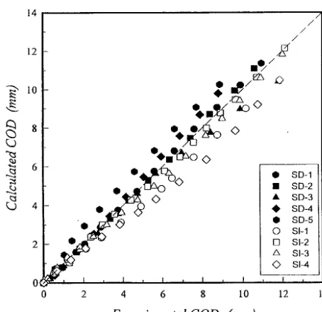
Eq. (18) was proposed on that propose and the appropriateness was investigated on the statically determinate piping system(SD) and the statically indeterminate piping one(SI) in this study. The comparison between the entire COD from the experiment and the one evaluated by Eq. (18) considering the incremental plastic rotation angle was represented in Fig. 9. It is known from the result of Fig. 9 that the experiments show a good consistence with the evaluated, regardless of the systems. From the above ones, it can be concluded that the COD evaluation model proposed in this study is appropriate for investigating the entire COD when a crack penetrates the wall thickness during a loading.
. . . , . . . : .. . . .! (a) combined tensile and bending specimen
(b) stress concentration specimen, ~-- 1.15
(c) stress concentration specimen, ~z = 1.48
Fig. 1 Photographs of fatigue fracture surface obtained from plate specimen
2 a b 1 B . . . ,
sl.
2as Surface J
(a)
(b)
-2 2 ae = 13as,+a b / 2
2W
2as
I _2ae
~x16 ~
Spe,l. Front Back Materials / ]THL <> @! IITS0 /._. I
" " "- I
I
• , e q . ( 4 ) I
I I I I I I I II
YD 5
<3
O
<3
0 0.1 0.2 0.3 0A 0.5 0.6 0.7 0.8 ae/W
Fig.3 Comparison of experimental with calculated values at the center of the plate of crack opening displacement.
(a) Cso/t = 2 . 6 4 , ~ ... = 196.0 M P a , O u t e r c r a c k (e) Cbo/t = 2 . 7 5 , ~ ... = 2 0 0 . 0 M P a , I n n e r c r a c k
(b) Cso/t = 0.71, ~ ... = 3 2 5 . 9 M P a , O u t e r c r a c k (f) Cbo/t = 0 . 7 4 , c~ ... = 2 1 0 . 0 M P a , h m e r c r a c k
(c) Cso/t = 0.71, q ... = 196.0 M P a , O u t e r c r a c k
• ,
(g) Cbo/t = 0 . 4 7 , .~ ... = 2 2 0 . 0 M P a , I n n e r c r a c k
, ~ Y:~!;!!:; iii i~?i!i i¸~¸~,~;
::
(d) Cso/t = 0.71, ~ ... = 2 3 9 . 6 M P a , O u t e r c r a c k (h) Cbo/t = 0.47, ~ ... = 2 6 1 . 0 M P a , h m e r c r a c k
(b) ... 2"c.~, ,.o o ,~ 1o' , ... - . . . ... • ... / - i
-- l ' "'"/'""'" ]i
.0"V
~ 0.,-" ~
10 4
[ ' 0.'*"~/ ~ : os ~ ob
- . . - = , . . . .
a
..[ .~..,
~8,8 .... ~ ! " [
I
o°
,.-~1
• ] - I
... ~ .... ,0,.l . , ,,t.~l - . L ~ _
[ Outer crack ] [ Inner crack ] o 1 z 3
9M = (Os+~,) 12 (rad.)
Fig. 5 M o d e l to e v a l u a t e t h e s t r e s s i n t e n s i t y f a c t o r a f t e r c r a c k P e n e t r a t i o n
Fig. 6 C o m p a r i s o n b e t w e e n e x p e r i m e n t a l a n d c a l c u l a t e d c r a c k o p e n i n g d i s p l a c e m e n t
6
(a) LBB Co) NO LBB
|
>l:AP
Neutral Axis _.
Fig. 7 L B B c o n d i t i o n u n d e r m o n o t o n i c load Fig. 8 M o d e l to e v a l u a t e C O D in pipe u n d e r a b e n d i n g m o m e n t
~ ' 10
8 8
~I
",~I~~°o
%
<:>O @
0 { ~ 1 I , I ~ I
0 2 4 6
/ /
if//
%~e~o o
/
/
• SD-1 • S D - 2 • S D - 3 • S D - 4 • SD-5 O S1-1 [ ] Sl-2 /k Sl-3
@ sl-4
I I I I ~ . . .
8 10 12 14
Experimental COD (mm)
CONCLUSIONS
The behaviors of crack opening displacement have been studied for plate and pipe specimens with a surface crack. The results obtained from the present study can be summarized as follows:
(1) The crack opening displacement at the center of the plate thickness was evaluated for all cases regardless of specimen size by using the equation and model proposed by authors.
(2) After crack penetration, the crack opening displacement was evaluated quantitatively for complex cracks by using the equation and pipe model proposed by authors.
(3) When a crack penetrated the wall thickness during a loading, the crack opening displacement from a through crack could be evaluated by using the incremental plastic rotation angle.
(4) This interesting observation warrants further study using various materials to determine its cause and tendency for the penetration behavior of a surface crack, and for possible application in relation to safety and the economics of structures.
R E F E R E N C E S
1. Nam, K. W., Ando, K. and Ogura, N., "The effect of specimen size on the behavior of penetrating fatigue cracks," Fatigue Fract. Engng Mater. Struct., Vol. 16, 1993, pp. 767-779.
2. Ando, K., Fujibayashi, S., Nam, K. W., Takahashi, M. and Ogura, N., "The fatigue life and crack through-thickness behaviour of a surface-cracked plate (for the case of tensile load)," JSME Int. J., Vol. 30, 1987, pp. 1898-1905.
3. Nam, K. W., Ando, K., Ogura, N. and Matsui, K., "Fatigue life and penetration behaviour of surface-cracked plate under combined tensile and bending stress," Fatigue Fract. Engng Mater. Struct., Vol. 17, 1994, pp. 873-880.
4. Nam, K. W., Ando, K., Sakai, Y. and Ogura, N., "Leak-before-break-conditions of plates and pipes under high fatigue stresses," Fatigue Fract. Engng Mater. Struct., Vol. 15, 1992, pp. 809-824.
5. Ahn, S. H., Hidaka, A. and Ando, K., "Fatigue crack growth and penetration behaviour in a pipe subjected to bending load," In: Engineering Against Fatigue, Edited by J. H. Beynon et al. Balkema, Rotterdam, The Netherlands, 1999, pp. 73-82.
6. Yoo, Y. S., Ahn, S. H. and Ando, K., "Fatigue crack growth and penetration behaviour in a pipes subjected to bending moment," ASME PVP, Vol. 371, 1998, pp. 63-70.