Abstract
KUNCICKY, DANIEL MELVIN. Characterization and Engineering of the Process of Directed Particle Self-Assembly in Thin Films and Sessile Droplets. (Under the direction of Professor Orlin D. Velev).
Directed self-assembly of colloidal particles confined between a solid and liquid interface has been studied as a versatile tool for organizing 2D and 3D crystalline arrays on solid substrates. The overarching goal of this study was to engineer the process of assembly to achieve simple and cost effective solutions for application needs were self-assembled particle structures work better than microfabricated ones. Two technologically relevant geometrical motifs of assembly were studied in detail. A thin film assembly technique based on controlled withdrawal of a meniscus was employed for modifying solid substrates with arrays of organic and inorganic colloidal particles. The assembled particles were used as a template for sterically directing the meso- and micro structure of metallic films for control over their electro-optical functionality. A sessile droplet templating technique was developed for fabricating arrays of discrete colloidal crystal patches of controlled shape and size. The process of assembly was studied in detail for each motif to optimize the deposition conditions and formulate protocols for controlling the size, composition, internal particle symmetry and overall shape. The methods and the results developed are relevant to different disciplines, including self-assembly, surface chemistry, Atomic Force Microscopy methodology, biological research and spectroscopy.
A single-step method for rapidly assembling tobacco mosaic virus (TMV) into nanocoatings and macroscopically ordered fibers was developed. Uniform films with long-range alignment or arrays of virus bundles were formed through a combination of shear and dewetting. Discrete, contiguous arrays of the TMV fibers were coated over centimeter length scales using only microliters of TMV suspension. The density and branching of the wire structure were controlled by varying the substrate wettability and meniscus withdrawal speed. The ability to precisely control the wire structure of the bio-scaffold allowed for the fabrication of architectures with advanced chemical and physical functionality. As an example, a procedure was developed where the TMV fibers were conjugated to Au particles followed by Ag enhancement for metal deposition. The procedure developed was used to convert the virus fibers into anisotropically conductive arrays of long wires.
Characterization and Engineering of the Process of Directed
Particle Self-Assembly in Thin Films and Sessile Droplets
by
Daniel M. Kuncicky
A Dissertation Submitted to the Graduate Faculty of North Carolina State University
in partial fulfillment of the requirements for the Degree of
Doctor of Philosophy
Chemical Engineering
Raleigh, North Carolina May 2007
Acknowledgements
First and foremost I thank my parents who have provided endless love, guidance and support. I could not have done this without them.
Orlin Velev has been a mentor and source of inspiration throughout this journey. He has shared with me his vision and enthusiasm for scientific innovation. I am indebted and grateful.
I also want to thank John van Zanten and Stefan Franzen for many insightful and fruitful discussions, Oscar Crisalle and Peter Kilpatrick for inspiring me to go to North Carolina State University in the first place, and also Steven Christensen, Rajesh Naik, Brian Prevo, Jason Guicheteau and David Phillips with whom I have had the privilege to work productively with over the last several years.
The staff from the Chemical and Biomolecular Engineering Department have been a godsend. Kit Yeung has kept our equipment in working order when no one else could. Sheila Hayes, Clarice Whitmarsh, Diane Harper, Sandra Bailey, Saundra Dobey, Gwen Johnson, Shirley Kow and all the rest have helped to jump over bureaucratic hurdles, navigate the fax machine and generally take care of business.
Biography
Daniel Kuncicky was born to David Kuncicky and Marcia Schambeau on May 8th, 1976. He was raised in Tallahassee, a mid-sized southern city situated between the coastal white sand barrier islands and piney woods of North Florida. He has a younger half-sister and numerous cousins and relatives who still live in the area. They carry on that tradition started by his great-grandfather who set up shop in Kissimmee, FL long before Disney World moved in.
Table of Contents
List of Figures... vi
List of Tables... xi
Chapter 1. General Background and Principles Used in the Fabrication and Application of Colloidal Crystals... 1
1.1. Introduction... 2
1.2. Evaporation-Driven Assembly of Particles Confined Between a Solid and Liquid Interface... 4
1.2.1. Sessile Droplet Deposition... 4
1.2.2. Thin Film Assembly ... 9
1.3. Template-Directed Assembly within Colloidal Crystals... 11
1.4. Engineering Applications of Porous Metallic Films Assembled in Colloidal Crystals... 14
1.4.1. Raman Spectroscopy... 14
1.4.2. Considerations for Engineering of SERS Substrates for Sensors... 17
1.5. Layout of Dissertation... 18
1.6. References... 18
Chapter 2. Role of the Meso- and Microstructure in the Performance of a SERS Sensor Assembled from Gold Nanoparticles... 28
2.1. Introduction... 29
2.3. Experimental... 31
2.3.1. Materials ... 31
2.3.2. SERS Substrate Deposition... 32
2.3.3. Sample Preparation and Data Collection ... 33
2.3.4. Experimental Methodology ... 34
2.4. Results and Discussion... 35
2.4.1. SERS Substrate Structure Characteristics... 35
2.4.2. Effect of Substrate Structure on SERS Response: Role of Meso- and Microporosity... 38
2.4.3. Effect of Gold Nanoparticle Surface Loading ... 40
2.4.4. Statistical Analysis of Substrate Variability ... 42
2.5. Concluding Remarks: Engineering of Substrate Structure... 44
2.6. Acknowledgements... 45
2.7. References... 46
Chapter 3. Rapid Deposition and Long Range Alignment of Nanocoatings and Wires from Tobacco Mosaic Virus... 48
3.1 Introduction... 49
3.2. Experimental Section... 51
3.2.1. Materials ... 51
3.2.2. Coating Procedure... 51
3.3.4. Characterization ... 52
3.3. Results and Discussion... 52
3.3.1 Effect of Substrate Wettability... 52
3.3.2. Electroless Nanoparticle Conjugation and Silver Plating to the TMV Fibers ... 58
3.5. Acknowledgments... 61
3.6. References... 61
Chapter 4. Colloidal Crystal Formation from Drying Sessile Droplets... 64
4.1. Introduction... 65
4.2. Materials and Methods... 67
4.2.1. Colloidal Suspension and Substrate Preparation ... 67
4.2.2. Colloidal Crystal Micropatch Preparation ... 68
4.2.3. Data Collection and Analysis... 69
4.2.4. Atomic Force Microscope Cantilever Mounting ... 70
4.3. Kinetic Equations for Drying of Sessile Droplets under Diffusion Control... 70
4.4. Results and Discussion... 73
4.4.1. Effect of Particle Concentration and Substrate Contact Angle on Micropatch Shape... 73
4.4.3. Shell Formation... 80
4.4.4. Effect of Electrolyte on the Process of Meniscus Templating... 81
4.5. Potential Applications... 85
4.5.1. 'Inverse Opal' Gold Nanoparticles Micropatches: SERS Substrates ... 85
4.5.2. Permeable Microindenters for Biomechanical Characterization ... 89
4.5. Conclusions... 92
4.7. Acknowledgements... 93
4.8. References... 93
Chapter 5. Summary... 98
List of Figures
Figure 1.1. Schematic of the mechanism of 2D crystallization in drying thin films and droplets with vanishing contact angle. Strong lateral capillary forces direct the crystallization along the drying front. (b) Optical micrograph of the actual process of particle advection towards the drying front showing the importance of convection in the process of film growth. The contrails showing the actual trajectories of the particles have been acquired by overexposing the film. Image in (b) from [20] ... 5 Figure 1.2. Mechanism of the process of convective assembly in thin films and droplet with
pinned contact line. (top) Schematic of the process leading to formation of multilayered colloidal crystals by convection-assisted particle transport towards the three-phase contact line. (bottom) Illustration of the attractive capillary forces that lead to particle rearrangement and crystallization at the periphery... 6 Figure 1.3. Schematic of the two distinctive evaporation modes with sessile droplets. The
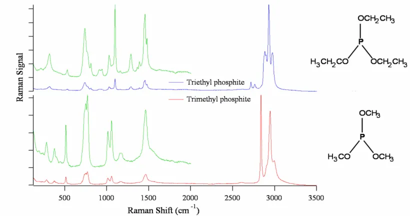
effect of contact line dynamics on the final micropatch architecture is illustrated. ... 8 Figure 1.4. Plots of the intensity of Raman scattered photons versus the Raman Shift of
chemically similar species showing the chemical “fingerprint” nature of the spectra. Concentrated samples are typically required for collecting such Raman spectra, however the intensity of the bands can by surface-enhanced (shown in green) when the molecules are adsorbed on suitable prepared conducting metallic substrates. ... 14 Figure 1.5. Energy level diagram for Rayleigh scattering, Stokes Raman scattering and
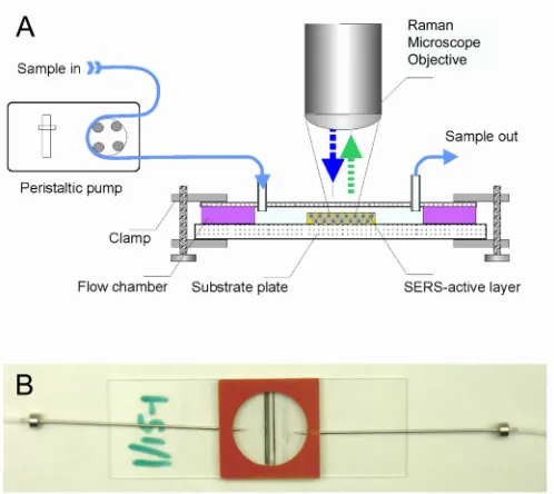
ant-Stokes Raman scattering. The upward and downward arrows represent the incident and scattered photon energy. ... 16 Figure 2.1. (A) Schematic diagram of the experimental system used to evaluate the
performance of SERS substrates. (B) Photograph of a millifluidic flow chamber
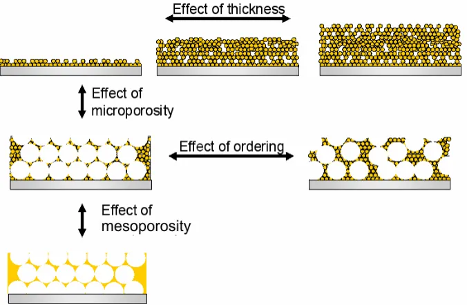
containing the SERS substrates films. ... 30 Figure 2.2. Schematic of the types of SERS substrates used in the systematic investigation of
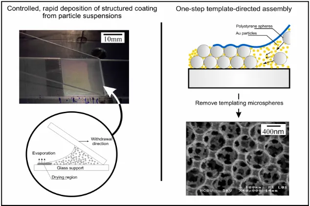
the effect of gold nanoparticle loading, and substrate meso- and microstructure, on the SERS effectiveness. ... 31 Figure 2.3. Schematic for the one-step deposition of nanostructured substrates used in this
study. The gold nanoparticles in our method are mixed with sub-micron sized latex microspheres. The microspheres form long-range ordered colloidal crystals by
convective assemble as the meniscus is controllable withdrawn. The gold nanoparticles are aggregated in the void spaces around the microspheres, and form a structured
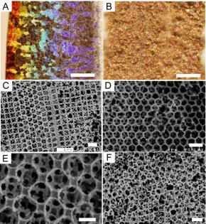
metallic film that is preserved when the polymer template is dissolved. ... 32 Figure 2.4. Optical and SEM micrographs of different structures that can be created in the
templated SERS substrates. (A) Ordered region at low magnification, optical
microscopy. The colors come from the long-range ordered arrays; (B) Disordered region at low magnification; (C) Mixed bilayer at high magnification, SEM; (D) Hexagonal bilayer at high magnification, (E) Square bilayer, (F) Disordered region. The scale bars dimensions are: A, B - 250 µm, C, D, F - 1 µm, E - 500 nm... 34 Figure 2.5. (A) UV/VIS spectra showing the relative transmission for non-templated SERS
Figure 2.6. (A) Characteristic sodium cyanide spectrum after 10 minutes of 75 ppb NaCN in 0.1 M NaOH (2125 cm-1), and after subsequently passing deionized water through the flow cell (2133 cm-1). (B) Characteristic sodium cyanide spectra for ordered latex templated (top), disordered latex-templated (middle), and non-templated (bottom) SERS substrates. (C) Averaged intensities of the 2125 cm-1 and the 2133 cm-1 peaks collected from each SERS substrate type (five data points from each substrate). ... 37 Figure 2.7. (A), (B) Optical and SEM micrographs of the SERS substrate after (left), and
before (right) fusion of the Au nanoparticles. SEM shows that the microscale features have been preserved. (C) Raman spectra collected sequentially (shown from left to right) from the highly annealed end to the non-annealed end. The scale bar dimensions are: A – 1mm, B – 1 µm. ... 39 Figure 2.8. Averaged cyanide peak intensity for SERS substrates with different thicknesses at high (A) and low pH (B)... 41 Figure 2.9. Distribution of Raman intensity data for disordered and ordered templated
substrates (cf. with Fig. 2.4) for 75 ppb cyanide. The data scattering was 25% for the ordered templated substrate and 17% for the disordered templated substrate... 42 Figure 2.10. (A) Receiver operating characteristic curves calculated from a sample size of 60 data points for each concentration. (B) Limit of detection based on a 5% probability of false alarm... 44 Figure 3.1. (a) Bright field image of a freely receding meniscus showing TMV fiber
alignment in suspension normal to the three-phase contact line from a suspension of 40 mg/mL TMV suspension. Appearance of the phase separated aggregated at concentration of (b) 5 mg mL-1 and (c) 40 mg mL-1 in 10 mM phosphate buffer at pH 6.8... 50 Figure 3.2. Schematic of the apparatus for depositing aligned virus fiber coatings. The TMV
suspension is entrained between the two plates. The top plate is attached to a linear motor and controllable withdrawn over the bottom substrate as the suspension
evaporates. ... 50 Figure 3.3. SEM micrographs of (a) 5 mg mL-1, (b) 10 mg mL-1 and (c) 59 mg mL-1 TMV
suspension deposited on hydrophilic substrates at a meniscus withdrawal velocity of 21.1 µm/s (d) AFM micrograph of an individual fiber from c) showing the TMV virion alignment direction. The experimental conditions are 40 % relative humidity and 22° C. Scale bars are a) – c) 5.0 µm and d) 0.25 µm. ... 52 Figure 3.4. SEM micrographs of cross-sectioned TMV fibers deposited at a) 40 % humidity
and b) 2% humidity showing the effect of evaporation rate on film thickness. Scale bars in a) and b) are 2 µm and 5 µm... 53 Figure 3.5. SEM micrographs of a) 59mg mL-1 and b) 10 mg mL-1 suspensions deposited at 2
% relative humidity showing the effect of TMV concentration on fiber alignment direction at the enhanced evaporation rate. The meniscus withdrawal velocity was the same as in Figure 3.3. Scale bars in a) and b) are 2 µm and 10 µm. ... 54 Figure 3.6. Proposed mechanism of assembly on hydrophilic substrates. (top) Pre-ordering
evaporation rates promotes fiber deposition orthogonal to the direction of meniscus withdrawal when depositing dilute, less viscous TMV suspensions. ... 54 Figure 3.7. Structure of the virus films when the meniscus was rapidly withdrawn across the
hydrophilic substrate at a rate of 147.7 µm s-1. Scale bars in a) and b) are 10µm and 2
µm. ... 56 Figure 3.8. Phase contrast optical image of the freely receding meniscus of a sessile droplet
on a hydrophobic substrate. The process of fiber coalescence is nucleated by dewetting at the contact line. Scale bar is 100 µm. ... 57 Figure 3.9. Dark field optical images of TMV wire deposition on hydrophobic substrates at
withdrawal speeds of (a) 5 µm s-1, b) 21 µm s-1 and (c) 60 µm s-1. Scale bars are 25 µm. ... 57 Figure 3.10. (a) Schematic of the procedure for fixation, Au nanoparticle conjugation, and
Ag enhancement of the TMV wires. (b) UV/Vis absorption spectra of the coated
substrate after the stages of (ii) glutaraldehyde fixation, (iii) Au conjugation, and (iv) Ag enhancing. ... 58 Figure 3.11. (a, c) Bright field optical and (b) SEM images of Ag-enhanced virus wires.
(d) I-V curves for the inline and crossed measurements. Conductivity measurements were performed using a two-terminal probe with a 20 mm gap. The points in the I-V curves are averaged results from 60 randomly chosen spots taken over the coated
substrate. ... 60 Figure 4.1. Optical micrographs showing examples of the a) ring stain and b) spherical cap
geometry. The micropatches were deposited by drying microliters of suspension on substrates of controlled wettability. c) SEM micrograph of a micropatch deposited from nanoliters of suspension d) SEM micrograph showing the polycrystalline ordering of the micropatch in (b). The scale bars shown in (a – d) correspond to 0.5 mm, 0.25 mm, 0.75 µm, 2 µm... 66 Figure 4.2. The height, h, contact radius, R, cross-section area, A and contact angle θare
measured from side profile digital images. Based on the spherical cap geometry, any two of these measurables can be used to calculate droplet volume, V. ... 69 Figure 4.3. (a) Typical optical images of dried micropatches showing the effect on
micropatch shape of varied particle concentration and substrate contact angle. Scale bars from top to bottom - 0.5, 0.5, 1.3, 2.0 mm (b) Categorized micropatch shape as a function of θr and φi determined from top and side view optical micrographs. The
drawn cross-sectional profiles show how patch architecture varies with volume fraction and contact angle. The open circles (○) are experimental data points corresponding to patches with convex shape and the crosses (×) to patches with concave shape. The darker shaded area on the bottom marks constant contact area drying dynamics. The line to guide the eye shows the predicted edge transition corresponding to the most uniform and flat micropatches. ... 73 Figure 4.4. Circularity values calculated from side view optical micrographs like those from
Figure 4.3a used to quantify how final shape is correlated to the experimental variables. ... 74 Figure 4.5. Drying droplet profile determined from side profile digital images taken at ten
101°. The innermost profile corresponds to the final micropatch shape. Experiments conducted at 40 % RH and 22° C. ... 74 Figure 4.6. Drying dynamics on a, b) hydrophobic surface with θr = 101°, and c, d)
moderately hydrophobic surface with θr = 80°. The measurements were taken from
edge profiles like those shown in Figure 4.5. ... 76 Figure 4.7. Close up of drying dynamics on hydrophobic substrates with a) θ = 101° and b) θ
= 81° during the final stages of evaporation. The grey lines indicate the point of contact line pinning. ... 77 Figure 4.8. The ratio of time of contact line pinning to total drying time as a function φi and
θr. Numerical values determined from Figure 4.7. ... 78
Figure 4.9. Experimentally measured dynamic change in particle concentration, and the interpolated theoretical predictions for φi = 5, 4, 3, 2 and 1 vol %. Interpolations
calculated using Equation 4.10 with the physical parameters from Table 4.3. ... 79 Figure 4.10. The a) experimental and d) theoretical transmittance plots used to identify the
formation of a thin shell at the air-water interface during drying. The experiment was performed with φi = 0.5 vol % and using the transparent polystyrene substrate with θr =
80°... 81 Figure 4.11. Dried micropatches assembled from suspensions of 7 wt % PS microspheres on
a substrate with θr = 80° at 22° C and 50 % relative humidity. The amount of added
KCL was 0.02, 0.17, 17.0, 67.0, 134, 168 mM (from top to bottom). The schematic shows the proposed mechanism of assembly corresponding to electrolyte concentration: a) below the critical pinning concentration (CPC), b) in between the CPC and the
critical coagulation concentration (CCC) and c) above the CCC. Scale bar = 0.6 mm. 82 Figure 4.12. a) Dynamic change in contact area, related to the b) average KCl concentration n
the shrinking drop. The point of contact line pinning is demarcated by the break in the contact area plots. The vertical lines highlight this break to demarcate the KCl
concentration at τpin for identification of the critical pinning concentration. ... 83
Figure 4.13. Optical micrographs of micropatches made from a mixture of gold
nanoparticles and a) 250 nm, b) 300 nm, and c) 600 nm PS microspheres. Experimental conditions were: 2:1 ratio of 5 wt % Au and 16 vol % PS, θr = 81°. The scale bars corresponds to 0.3 mm... 87 Figure 4.14. Typical microstructure when using a mixture of gold nanoparticles and PS
microspheres. The a) optical and corresponding b) SEM micrograph of the lens structure shows the inner curvature and arrangement of gold nanoparticle aggregated around PS microspheres. c, d) SEM micrographs of the lens in a, b) after heating in air to remove the PS microspheres. e) Optical and corresponding f) SEM micrograph of a templated micropatch after removing the PS component by washing with methylene chloride. The scale bars for a – f correspond to 10 µm, 1 µm, 10 µm, 1 µm, 0.4 mm and 1 µm. ... 88 Figure 4.15. Schematics of the set-up and the principle of assembly. (a) Photograph of the
spray particle assembly apparatus, and (b) mechanism of particle templating in a drying sessile droplet... 90 Figure 4.16. SEM micrographs showing the microstructure of hemispherical assemblies
List of Tables
Table 2.1. The effect of ordering on the average Raman intensity and data scattering over a range of concentrations. ... 43 Table 4.1. Description and properties of substrates used in the sessile droplet templating
experiments. ... 67 Table 4.2. Summary of results for the drying dynamics experiments conducted on
1.1. Introduction
This work is the culmination of my efforts to engineer processes for fabricating meso- and macrostructured assemblies from liquid suspensions of colloidal particles. Specific interest in such materials derives from the potential for tuning the collective electro-optical, mechanical or chemical functionality through control over composition, internal particle symmetry and overall shape. The overarching aim has been to find simple and cost effective solutions for application needs were self-assembled particle structures work better than microfabricated ones. The goal of this chapter is to summarize the principles used in the self-assembly of colloidal materials from liquid dispersion onto surfaces, discuss the underlying mechanisms, and present examples of materials obtained and their potential applications.
Self-assembly encompasses any spontaneous organization of molecules or objects into well-defined aggregates via noncovalent interactions. The physical principles governing self-assembly and organization ultimately determine the properties and behavior of much of the universe, from large scale astronomical and meteorological events down to physiological function at the cellular and molecular level. During the 20th century fundamental developments in the understanding of colloidal phenomena brought forward new knowledge marked by improved formulations of paints and coating, improved processing of emulsions and foams, and novel uses for polymer systems. Now the promise of nanoscience and technology is being spurred by the discovery of particles with extraordinary mechanical and electro-optical properties (e.g., fullerenes, carbon nanotubes, quantum dots) along with increased access to high resolution instruments for characterizing structures at small length scales (e.g., scanning probe, atomic force microscopy, electron microscopy).
arrangement of dielectric material having spatial periodicity on the scale of optical wavelengths, and can exhibit unique optical phenomena such as a full-photonic band gap and generation and manipulation of light over small regions. Assembled metallic particles with nanoscale features possess unique attributes that arise from coupling to plasmons in the metal layer. Localized plasmonic modes at the interfaces between conducting and dielectric materials create regions of enhanced electromagnetic field strength that could serve as signal amplifying elements for optical sensing devices.
Particle assemblies could also serve as a basis for catalytic materials formed from aggregated or fused particles with high surface area to volume ratio, homogenous porosity, and good mechanical properties, which will maximize their catalytic reactivity, throughput and stability. Responsive smart particles and particle/gel matrices are another emerging class of functionalized colloidal systems. The advantage of such systems is that they can be tailored to passively respond to changes in environmental conditions such as temperature, composition or pH.
1.2. Evaporation-Driven Assembly of Particles Confined Between a Solid and Liquid Interface
Direct patterning of 1D, 2D and 3D assemblies from colloidal particles onto surfaces could be a critical element in the development of emerging nanotechnologies. A promising colloidal assembly methodology is based on spreading a droplet or thin film on a surface and allowing it to dry. Many of the underlying colloidal and dynamic interactions controlling the process are understood. In this section I present the basic fundamentals elements and engineering techniques most relevant to the problems worked on for this dissertation.
1.2.1. Sessile Droplet Deposition
Methods using deposition of non-volatile components from sessile droplets are used in a variety of technologies and applications. Simple evaporation of a drop of suspension accounts for the commonly observed ring stain, and is critical important in painting and ink jet printing, as well as in methods for DNA microarray deposition.[10-12] At first glance, colloidal assembly from sessile droplets seems to be a simple method for fabricating arrays of 3D crystalline micropatches. After all it is easy enough to pipette a small volume of suspension onto surface and let it dry. As it turns out, controlling the spatial arrangement, crystal quality and overall shape of the particle assembly is no trivial task. The difficulty controlling the process arises because a variety of colloidal and dynamic interactions govern assembly in drying drops.
Figure 1.1. Schematic of the mechanism of 2D crystallization in drying thin films and droplets with vanishing contact angle. Strong lateral capillary forces direct the crystallization along the drying front. (b) Optical micrograph of the actual process of particle advection towards the drying front showing the importance of convection in the process of film growth. The contrails showing the actual trajectories of the particles have been acquired by overexposing the film. Image in (b) from [20]
bulk. The fluid motion carries the particles towards the contact line where they are incorporated into the growing particle assembly. The horizontal particle advection was observed with optical microscopy proving the importance of convective flow (Fig. 1.1b). Direct visual confirmation of the process, both in thin wetting films and droplets, has lead to wide spread acceptance of this mechanism of 2D assembly from thin films and droplets with vanishing contact angle.
Figure 1.2. Mechanism of the process of convective assembly in thin films and droplet with pinned contact line. (top) Schematic of the process leading to formation of multilayered colloidal crystals by convection-assisted particle transport towards the three-phase contact line. (bottom) Illustration of the attractive capillary forces that lead to particle rearrangement and crystallization at the periphery.
Deegan et al. formulated a mathematical basis for describing the convective flow responsible for particle transport in the drying drops.[13] Their theoretical analysis is based on the fact that the equilibrium shape of the drop is maintained as solvent evaporates. They showed that if the contact line is pinned, the loss of solvent to evaporation necessarily squeezes the fluid outward as the meniscus flattens. A number of studies have also described the effect of the spatially varying evaporation rate on internal flow patterns within the drying drop.[13, 14, 16, 17, 27] Hu and Larson improved upon the model of Deegan et al. and included the effects of Marangoni stresses. Marangoni stresses are caused by a surface tension gradient due to a concentration gradient or temperature gradient at the air-liquid interface. Due to the difference in heat conduction path length across drops of large contact angle, as the droplet evaporates a non-uniform temperature distribution is established by evaporative cooling from the meniscus. The cooler part of the drying drop has a higher surface tension and therefore pulls more strongly on the surrounding liquid than the warmer regions with lower surface tension. In the process, an inward circulatory flow could be formed.[28] Although such theoretical analysis has demonstrated that internal circulation by Marangoni convection can be important, Hu et al. and Deegan et al. later proved experimentally that the circulation is quite weak for sessile droplets of water suspensions on moderately hydrophilic substrates.[14, 17] The experiments reinforced the connection between circulatory flow patterns and the distribution of particles deposited onto the solid surface. Based on this type of analysis it has been suggested that staged temperature control could be useful for making uniform coatings by balancing outward convective assembly with temperature-enhanced Marangoni convection to the droplet center.[29] Chang and Velev successfully demonstrated fabrication of 3D colloidal crystal structures based on such circulation driven assembly in freely suspended spherical drops.[30] Attempts to exert intricate flow control in sessile drops have so far proven difficult.
is a major operating parameter for controlling the process of colloidal assembly from sessile droplets.
A number of research groups have studied the problem of dynamic wetting on solid surfaces for systems of pure liquids. Early studies by Birdi and Vu related the drying mode
Figure 1.3. Schematic of the two distinctive evaporation modes with sessile droplets. The effect of contact line dynamics on the final micropatch architecture is illustrated.
to the evaporation kinetics. A range of substrates of varied wettability and liquids of varied volatility were studied. They attempted to categorize their results in terms of contact angle alone, and noted that for initial contact angles greater than 90°, the evaporation rate is nonlinear and follows constant contact angle dynamics, while for initial contact angle less than 90° the evaporation rate is linear and follows the constant contact area dynamics.[31] Based on such studies, two distinctive modes of sessile droplet evaporation have been identified.[31-33] The droplet could dry with constant contact area and decreasing contact angle, or constant contact angle and decreasing contact area. Although this picture is oversimplified it is useful in illustrating the potential impact of such limiting cases on colloidal crystal formation (Fig. 1.3).
sessile droplets on both smooth and rough epoxy surfaces and observed hysteresis-driven oscillations between fixed area and fixed angle dynamics [34]. Recent key advances in understanding and fabrication of surfaces of controlled contact angle hysteresis are leading to emerging classes of advanced materials that exhibit 'self-cleaning' properties and other unusual behavior such as the ability to move water droplets 'uphill.'[35, 36]
The drying of droplets from particle suspensions introduces an additional set of complexities. Even the addition of minute concentrations of suspended particles can drastically alter the behavior of drying droplets. Particles entrained near the contract line can inhibit dewetting. Adachi et al. calculated the balance of forces on the meniscus when particles jam in the wedge region that forms near the periphery. Based on their analysis it was suggested that pinning was more likely to occur at lower contact angles with viscous particles flow towards the three-phase contact line.[13] Particles can also accumulate at the meniscus due to surface energy effects and dynamic processes.[37-39] The particle concentrated and confined at the air-liquid interface can also lead to visco-elastic transitions that drastically alter the contact line dynamics and result in stress-induced buckling and warping of the templating meniscus.
The complex interplay between contact line dynamics, internal flow, and the range of capillary forces and colloidal interactions may promote or inhibit formation of high quality, uniform colloidal crystals. To control the process of sessile droplet templating it would be useful to understand the physical dynamics of drying as related to the evaporation mode. Facile control over micropatch architecture could also be enhanced through better understanding of the effect of technologically relevant parameters controlling the process. The understanding developed could benefit a variety of technological applications and research areas that utilize deposition of non-volatile components from an evaporating drop.
1.2.2. Thin Film Assembly
surprisingly, formation of colloidal crystals from drying films were first reported over fifty years ago.[40-42] Since then the major engineering challenges have centered on developing adjustable and well-defined coating processes for controlling the position of the drying front and thickness of the film.
Dip coating was one of first techniques for linear deposition of uniform coatings over large areas.[43] In the simplest set-up, a hydrophilic glass plate is partially submerged in a reservoir containing the suspension. As the solvent evaporates the meniscus moves across the surface in an oscillatory stick-slip motion. The particles are carried by the convective assembly process towards the growing crystalline area at the drying front. With this setup, control over the speed of assembly and number of layers deposited is quite limited since the meniscus recedes at a velocity determined by the evaporation rate. In a variation of this technique, the substrate is attached to a linear motor for controllable withdrawal. Since the rate of crystal growth is limited by the particle flux towards the crystallizing region, adjusting the withdrawal rate allows for controlling the number of layers deposited.[44] Prevo and Velev later improved upon the process by entraining a small volume of the particle suspension between two glass plates. The top plate is used to drag the suspension linearly across the bottom substrate.[23] The process is effectively the same as dip coating, with the advantage that much less material is required.
Dimitrov and Nagayama related the meniscus withdrawal velocity, νc, to the particle
concentration, φ, and film thickness, h, by a simple steady-state volumetric flux balance on the particles and solvent near the drying front.[45] A slightly simplified version of Dimitrov and Nagayama’s equation was formulated by Prevo and Velev [23] (Eqn. 1.1)
) 1 )( 1 ( ε φ φ − − = h K
vc (1.1)
where ε is the porosity and Κ is the 'drying length.' Κ is used to correct for the lag time between the particle velocity and solvent velocity, and in general depends on the evaporation rate and particle size. An 'operational phase diagram' was developed which relates νc and φ
process of thin film assembly because they provided an operational basis for controlling the film thickness and structure with easily adjustable parameters.
1.3. Template-Directed Assembly within Colloidal Crystals
Colloidal crystals have been used as templates for directing the assembly of a range of organic and inorganic materials into ordered 2D and 3D structures with controlled porosity. The colloidal crystal serves as a stable, and typically sacrificial, matrix for depositing an active material in the interstitial space within the template. Latex and silica microspheres in the 100 nm to 1 micron range are typically used as the templating material since they can be obtained as suspensions with uniform particle size and at affordable cost. Afterwards the spheres can be removed by a thermal or chemical etching treatment leaving an inverse replica of the colloidal crystal structure.
Research into synthesis of such materials is generally focused in two areas: assembly of the colloidal template, and infusion of the active material into the ordered matrix. In addition to the evaporation-driven assembly techniques presented in the previous section, methods based on sedimentation [49-51], centrifugation [52-54] and filtration [55-57] have shown promise. The predominant crystalline microstructure formed with such techniques is hexagonal close-packed with (111) plane oriented parallel to the deposition substrate. These materials are typically polycrystalline due to multiple nucleation sites along the crystallizing regions and size dispersity in templating sphere diameter.[46] Arrays with square ordering are occasionally observed at grain boundaries, but they appear to be a transition phase between the more stable hexagonally packed regions. Square arrays are the thermodynamically preferred organization in layers of certain thickness,[47] however they are rarely observed in convectively assembled films deposited from latex spheres. This is likely due to the flexibility of the liquid/air interface, which permits particle protrusion through the liquid meniscus, hence allowing the formation of the hexagonal, rather than square, arrays.[48]
been fabricated by epitaxial growth on microfabricated substrates as well.[62] In this approach periodic recess features of specific symmetry direct the crystal organization. Although slow and difficult to scale up this method has gained attention and may be critical to growing defect-free crystals for advanced optical applications.
The solid structures within the pores can be formed from liquid precursors by polymerization,[56,59,63] sol-gel hydrolysis,[52,53] precipitation,[54, 64] and electrochemical deposition.[65] The seminal demonstration of template-directed assembly in colloidal crystals was based on infusing a 3D colloidal crystal with aqueous silica.[55] The colloidal crystal was assembled by filtration of polystyrene (PS) microspheres on a porous membrane. Afterwards an aqueous solution of Si(OH)4 was filtered through the assembled matrix. The PS microspheres were functionalized with HTAB cationic surfactant which served to initiate sol-gel polymerization and epitaxial silica growth from the PS microsphere surface within the interstitial space. One of the first demonstrations of the compositional diversity of the technique was based on alkoxide hydrolysis for deposition of alumina, titania and zirconia.[53] A range of other compositions from oxides of W, Fe, Sb, Zr, aluminophosphates, carbonates and zeolites and others have also been assembled within highly-ordered 3D arrays of spherical voids.[54]
and since the technique is self-limiting the thickness of the deposited layer can be precisely controlled.
Structured porous metallic films assembled by template-directed assembly were the primary material of interest in this dissertation owing to the potential utility of such materials in a class of sensors based on surface-enhancing Raman spectroscopy (SERS). The first synthesis of porous metal by colloidal crystal templating was carried out using a two-step procedure.[64] A porous layer of NiO was first assembled in the colloidal crystal by templated precipitation. The oxide precursor could then by completely converted to a hierarchically porous Ni solid by reduction in hydrogen or to a Ni/NiO composite by partial reduction. Jiang et al. describe preparation of monolithic porous metal films using a mult-step 'wet' chemistry methodology.[43] In their approach the silica spheres functionalized with a thiol-terminated coupling agent are assembled by dip coating. Afterwards a solution of gold nanocrystals are infused into the porous network where they affix to the silica colloidal surface at the accessible thiols. The Au nanocrystals provide nucleation sites for electroless deposition of metals in the final step. This muli-step methodology has been used to form structured meso/macroporous 3D films from Ni, Cu, Ag, Au and Pt.
The droplet or thin film deposition techniques presented in sections 1.2.1 and 1.2.2 could be adapted for single-step fabrication of templated metallic nanostructures using binary mixture of sacrificial microspheres and metallic nanoparticles.[71] The micoparticles concentrated and confined in the thin film are ordered into a colloidal crystal by reduction of free volume and capillary immersion forces. The smaller nanoparticles added to the suspension infiltrate the interstitial space surrounding the larger sacrificial microspheres during the process of convective assembly. A major advantage of the single-step flow coating process is that it can be easily adapted for assembly on a range of surfaces.
Figure 1.4. Plots of the intensity of Raman scattered photons versus the Raman Shift of chemically similar species showing the chemical 'fingerprint' nature of the spectra. Concentrated samples are typically required for collecting such Raman spectra, however the intensity of the bands can by surface-enhanced (shown in green) when the molecules are adsorbed on suitable prepared conducting metallic substrates.
1.4. Engineering Applications of Porous Metallic Films Assembled in Colloidal Crystals 1.4.1. Raman Spectroscopy
light scattering is called Rayleigh scattering. There is also an exchange of energy and in the process the molecule is left in a different vibrational state. Such inelastic scattering is called the Raman effect. The Raman signal is measured by filtering out the intense laser line with a monochromator followed by counting the number of Raman scattered photons with a photomultiplier tube or CCD camera. The frequencies present in the radiation scattered by the excited molecule are a function of the molecular structure, chemical composition, and solvent. A typical example of Raman spectra collected from neat samples is shown in Figure 1.4. Such plots are often called fingerprint spectra because they are useful for distinguishing between chemical similar species based on the position and intensity of the peaks.
In quantum mechanical terms, the Raman effect is described as an electronic excitation to a virtual energy state followed by nearly coincident de-excitation, with emission of a photon and change in vibrational energy.[72, 73] The relaxation to the vibrational excited state (V1, V2, V3, etc..) generates Stokes Raman scattering. Molecules already in a vibrationally excited state scatter photons with higher energy by anti-Stokes Raman scattering. The difference in energy between the Raman scattered photon and incident photon, h(ν0 ± νj), is
equal to the energy of vibration of the scattered molecule.
Although the Stokes and anti-Stokes spectra contain the same spectral information, at room temperature the thermal population of vibrationally excited states is low, and hence, the intensity of the Stokes spectra is always more intense. For this reason, the Stokes bands are measured in routine analytical analysis. Since the Raman shift is plotted as a function of its frequency difference from the incident radiation, the position of the peaks (in cm-1) are independent of the laser frequency used. In contrast, the intensity of the Raman signal varies depending on the laser frequency. An excitation frequency that promotes true electronic resonances can result in an increase in the Raman signal of some Raman-active vibrations. In practice resonance enhancement does not occur at a sharply defined wavelength, but instead is observed within a few hundred wavenumbers below the electronic transition of vibronic mode in the molecule.[74]
Figure 1.5. Energy level diagram for Rayleigh scattering, Stokes Raman scattering and ant-Stokes Raman scattering. The upward and downward arrows represent the incident and scattered photon energy.
ratios thus making it difficult to detect chemicals at useful concentrations. A major breakthrough in addressing the sensitivity problem was the discovery of the surface-enhanced Raman scattering (SERS) effect. It was found that the surface-surface-enhanced signal of molecules chemisorbed at a metallic interface could be substantially amplified.[75-77] The mechanism of enhancement is not understood, although many groups are studying this problem. In the current state of thought, the surface enhancement is broken into separate chemical and electromagnetic contributions, although the two elements are most likely coupled.
The electromagnetic component is driven by surface plasmon excitations in the metal. Surface plasmons are collective excitations of electrons in the surface of a conductor. The surface plasmon resonance is supported by the conductor when excited below or at the plasma frequency. Topological features and nanoscale surface roughness allow for matching the momentum of the free space radiation and surface plasmon modes in the conductor. [78] The features can be random and sub-wavelength sized, or periodic as with a diffraction or
Energy
Excited Electronic State Virtual StateGround
State
V
3V
2V
1 Rayleigh Scattering Stokes Raman Anti-Stokes Raman 0hν hν0 h(ν0−νj) h(ν0+νj)
Resonance Raman
Energy
Excited Electronic State Virtual StateGround
State
V
3V
2V
1 Rayleigh Scattering Stokes Raman Anti-Stokes Raman 0hν hν0 h(ν0−νj) h(ν0+νj)
reflection grating.[79-84] When the metal is excited at the appropriate energy, intense evanescent fields are generated which rapidly decay within nanometers from the metal surface. The resulting energy density on the substrate surface strongly augments the Raman signal of species adsorbed in regions of high field intensity.[85] The more widely accepted explanations of the chemical effect all involve the formation of an adsorbate-metal interaction that engenders broadening and shifting of free molecular states. This results in a larger Raman scattering cross-section than for the non-adsorbed species, thereby promoting more efficient scattering of photons. [86]
1.4.2. Considerations for Engineering of SERS Substrates for Sensors
It has been found that the Raman enhancement strongly depends on the morphology of the metallic substrate. Silver, gold, and copper have yielded the largest SERS signal, and have been the most extensively studied, however, other transition metals have SERS activity as well.[87, 88] The major considerations for use of SERS substrates in sensors are stability, limit of detection and reproducibility of signal. This inspired a variety of techniques for SERS substrate fabrication. Examples include electrochemical roughening of metallic surfaces,[89-93] chemical etching of metallic surfaces,[94-98] vapor deposition onto roughened or lithographically prepared surfaces,[100-105] microfabrication of patterned metallic structures,[106] and a variety of approaches utilizing gold and silver particles.[107-120]
1.5. Layout of Dissertation
A thin film colloidal assembly technique based on the process illustrated in Figure 1.1 & 1.2 was used extensively throughout this dissertation for assembling organic and inorganic colloidal particles on solid substrates. The work presented in Chapters 2 and 3 builds upon the operational principles developed by Velev and Prevo (see section 1.2.2) and extends such principles for fabrication of an advanced class of hierarchically porous nanoparticle films. In Chapter 2 the meso- and microstructure of the films was systematically controlled and correlated to the technologically useful electro-optical properties for sensor applications. The data could be instrumental in understanding in better depth the origin of the surface-enhancing Raman scattering effects and also the factors that control substrate performance in SERS-based diagnostic assays. In Chapter 3 a new modification of the assembly process for depositing films, fibers and wires of tobacco mosaic virus through a combination of controlled shear and dewetting is presented.
The work presented in Chapter 4 details a newly developed sessile droplet deposition technique for assembling colloidal crystals in small dots and micropatches based on the principles illustrated in Figure 1.3. The process of assembly has been correlated to the dynamics of the receding contact line. The characterization of the process in detail was used to optimize the deposition conditions and formulate protocols for fabrication of structured patches of different diameter, thickness and shape. It is worthwhile to note that this is the first systematic study of colloidal crystal formation from drying sessile drops covering a range of substrate of different wettability. The understanding gained from this research could be widely beneficial to the variety of technological applications and research areas that require deposition of non-volatile components from evaporating droplets. The understanding developed from these results was used to engineer novel liquid-permeable compression probes for AFM based biomechanical characterization studies and templated Au nanoparticle substrates for SERS sensing in microarray format.
1.6. References
1. Xia, Y. N.; Gates, B.; Yin, Y. D.; Lu. Y., Monodispersed Colloidal Spheres: Old Materials With New Applications. Adv. Mater., 2000, 12, 693-713.
3. Xia, Y. N.; Yin, Y. D.; Lu, Y.; McLellan, J., Template-Assisted Self-Assembly of Spherical Colloids into Complex and Controllable Structures. Adv. Funct. Mater., 2003, 13, 907-918.
4. Velev, O. D.; Kaler, E. W., Structured Porous Materials Via Colloidal Crystal Templating: From Inorganic Oxides to Metals. Adv. Mater., 2000, 12, 531-534.
5. A. van Blaaderen. From the De Broglie to Visible Wavelengths: Manipulating Electrons and Photons With Colloids. Mrs Bulletin, 1998, 23, 39-43.
6. van Blaaderen, A.; Hoogenboom, J. P.; Vossen, D. L. J.; Yethiraj, A.; van der Horst, A.; Visscher, K. et al. Colloidal Epitaxy: Playing With the Boundary Conditions of Colloidal Crystallization. Faraday Discus., 2003, 123, 107-119.
7. A. van Blaaderen. Colloids Under External Control. MRS Bulletin, 2004, 29, 85-90.
8. Stein, A.; Schroden, R. C., Colloidal Crystal Templating of Three-Dimensionally Ordered Macroporous Solids: Materials for Photonics and Beyond. Curr. Opin. Solid State Mater. Sci., 2001, 5, 553-564.
9. Xia, Y. N., In Self-Assembly on Various Scales, Summer School on Nanoparticle Materials, Ypsilanti, MI, 2004; ACS-PRF.
10. Deegan, R. D.; Bakajin, O.; Dupont, T. F.; Huber, G.; Nagel, S. R.; Witten, T. A., Capillary flow as the cause of ring stains from dried liquid drops. Nature 1997, 389, 827-829.
11. Blossey, R.; Bosio, A., Contact line deposits on cDNA microarrays: A "twin-spot effect".
Langmuir 2002, 18, 2952-2954.
12. Dugas, V.; Broutin, J.; Souteyrand, E., Droplet evaporation study applied to DNA chip manufacturing. Langmuir 2005, 21, 9130-9136.
13. Adachi, E.; Dimitrov, A. S.; Nagayama, K., Stripe patterns formed on a glass-surface during droplet evaporation. Langmuir 1995, 11, 1057-1060.
14. Deegan, R. D., Pattern formation in drying drops. Phys. Rev. E 2000, 61, 475-485.
15. Conway, J.; Korns, H.; Fisch, M. R., Evaporation kinematics of polystyrene bead suspensions. Langmuir 1997, 13, 426-431.
16. Fischer, B. J., Particle convection in an evaporating colloidal droplet. Langmuir 2002, 18, 60-67.
17. Hu, H.; Larson, R. G., Marangoni effect reverses coffee-ring depositions. J. Phys. Chem. B
2006, 110, 7090-7094.
19. Denkov, N. D.; Velev, O. D.; Kralchevsky, P. A.; Ivanov, I. B.; Yoshimura, H.; Nagayama, K., Mechanism of Formation of 2-Dimensional Crystals From Latex- Particles on
Substrates. Langmuir, 1992, 8, 3183-3190.
20. Dimitrov, A. S.; Dushkin, C. D.; Yoshimura, H.; Nagayama, K., Observations of Latex Particle 2-Dimensional-Crystal Nucleation in Wetting Films on Mercury, Glass, and Mica. Langmuir, 1994, 10, 432-440.
21. Denkov, N. D.; Velev, O. D.; Kralchevsky, P. A.; Ivanov, I. B.; Yoshimura, H.;Nagayama. K., 2-Dimensional Crystallization. Nature, 1993, 361, 26-+.
22. Dimitrov, A. S.; Nagayama, K., Steady-State Unidirectional Convective Assembling of Fine Particles Into 2-Dimensional Arrays. Chem. Phys. Lett., 1995, 243, 462-468.
23. Prevo, B. G.; Velev, O. D., Controlled, rapid deposition of structured coatings from micro- and nanoparticle suspensions. Langmuir2004, 20, 2099-2107.
24. Dushkin, C. D.; Lazarov, G. S.; Kotsev, S. N.; Yoshimura, H.; Nagayama, K., Effect of Growth Conditions on the Structure of Two-Dimensional Latex Crystals:
Experiment. Colloid. Polym. Sci., 1999, 277, 914-930.
25. Kralchevsky, P. A.; Denkov, N. D., Capillary Forces and Structuring in Layers of Colloid Particles. Curr. Opin. Colloid Interface Sci., 2001, 6, 383-401.
26. Denkov, N. D.; Velev, O. D.; Kralchevsky, P. A.; Ivanov, I. B.; Yoshimura, H.; Nagayama, K., Mechanism of Formation of 2-Dimensional Crystals From Latex- Particles on
Substrates. Langmuir, 1992, 8, 3183-3190.
27. Hu, H.; Larson, R. G., Evaporation of a sessile droplet on a substrate. J. Phys. Chem. B 2002,
106, 1334-1344.
28. Hu, H.; Larson, R. G., Analysis of the effects of Marangoni stresses on the microflow in an evaporating sessile droplet. Langmuir 2005, 21, 3972-3980.
29. Chon, C. H.; Paik, S.; Tipton, J. B.; Kihm, K. D., Effect of nanoparticle sizes and number densities on the evaporation and dryout characteristics for strongly pinned nanofluid droplets. Langmuir 2007, 23, 2953-2960.
30. Chang, S. T.; Velev, O. D., Evaporation-induced particle microseparations inside droplets floating on a chip. Langmuir 2006, 22, 1459-1468.
31. Birdi, K. S.; Vu, D. T., Wettability and the Evaporation Rates of Fluids from Surfaces. J. Adhesion Sci. Technol. 1993, 7, 485-493.
32. Rowan, S. M.; Newton, M. I.; McHale, G., Evaporation of Microdroplets and the Wetting of Solid-Surfaces. J. Phys. Chem. 1995, 99, 13268- 13271.
34. Bourges-Monnier, C.; Shanahan, M. E. R., Influence of Evaporation on Contact-Angle.
Langmuir 1995, 11, 2820-2829.
35. Chaudhury, M. K.; Whitesides, G. M.,How to Make Water Run Uphill. Science 1992, 256, 1539-1541.
36. Blossey, R., Self-cleaning surfaces - virtual realities. Nat. Mater. 2003, 2, 301-306.
37. Gorand, Y.; Pauchard, L.; Calligari, G.; Hulin, J. P.; Allain, C., Mechanical instability induced by the desiccation of sessile drops. Langmuir 2004, 20, 5138- 5140.
38. Pauchard, L.; Parisse, F.; Allain, C., Influence of salt content on crack patterns formed through colloidal suspension desiccation. Phys. Rev. E 1999, 59, 3737- 3740.
39. Tsapis, N.; Dufresne, E. R.; Sinha, S. S.; Riera, C. S.; Hutchinson, J. W.; Mahadevan, L.; Weitz, D. A., Onset of buckling in drying droplets of colloidal suspensions. Phys. Rev. Lett. 2005, 94, 018302.
40. Alfrey, T.; Bradford, E. B.; Vanderhof, J. W.; Oster, G., Optical Properties of Uniform Particle-Size Latexes. J. Opt. Soc. Am., 1954, 44, 603-609.
41. Price, W. C.; Williams, R. C.; Wyckoff, R. W. G., The Electron Microscopy of Crystalline Plant Viruses. Science, 1945, 102, 277-278.
42. Wyckoff, R. W. G., The Electron Microscopy of Macromolecular Crystals. Acta Cryst., 1948, 1, 292-+.
43. Jiang, P.; Bertone, J. F.; Hwang, K. S.; Colvin, V. L. Single-crystal colloidal multilayers of controlled thickness. Chem. Mat., 1999, 11, 2132-2140.
44. Gu, Z. Z.; Fujishima, A.; Sato, O., Fabrication of high-quality opal films with controllable thickness. Chem. Mater. 2002, 14, 760-765.
45. Dimitrov, A. S., Nagayama, K., Continuous convective assembling of fine particles into two-dimensional arrays on solid surfaces. Langmuir 1996, 12, 1303-1311.
46. Kuncicky, D. M.; Prevo, B. G.; Velev, O. D., Controlled assembly of SERS substrates templated by colloidal crystal films. J. Mater. Chem. 2006, 16, 1207-1211.
47. Pieranski, P.; Strzelecki, L.; Pansu, B., Thin Colloidal Crystals. Phys. Rev. Lett.1983, 50, 900-903.
48. Pansu, B.; Pieranski, P.; Strzelecki, L., Thin Colloidal Crystals - a Series of Structural Transitions. J. Phys. 1. 1983, 44, 531-536.
49. Zakhidov, A. A.; Baughman, R. H.; Iqbal, Z.; Cui, C. X.; Khayrullin, I.; Dantas, S. O.; Marti, I.; Ralchenko, V. G., Carbon structures with three-dimensional periodicity at optical
50. Baughman, R. H.; Cui, C. X.; Zakhidov, A. A.; Iqbal, Z.; Barisci, J. N.; Spinks, G. M.; Wallace, G. G.; Mazzoldi, A.; De Rossi, D.; Rinzler, A. G.; Jaschinski, O.; Roth, S.; Kertesz, M., Carbon nanotube actuators. Science 1999, 284, 1340-1344.
51. Subramania, G.; Constant, K.; Biswas, R.; Sigalas, M. M.; Ho, K. M., Optical photonic crystals fabricated from colloidal systems. Appl. Phys. Lett. 1999, 74, 3933-3935.
52. van Blaaderen, A.; Ruel, R.; Wiltzius, P., Template-directed colloidal crystallization. Nature
1997, 4, 385-321.
52. Imhof, A.; Pine, D. J., Ordered macroporous materials by emulsion templating. Nature 1997,
389, 948-951.
53. Holland, B. T.; Blanford, C. F.; Stein, A., Synthesis of macroporous minerals with highly ordered three-dimensional arrays of spheroidal voids. Science 1998, 281, 538-540.
54. Yan, H. W.; Blanford, C. F.; Holland, B. T.; Smyrl, W. H.; Stein, A., General synthesis of periodic macroporous solids by templated salt precipitation and chemical conversion.
Chem. Mater. 2000, 12, 1134-1141.
55. Velev, O. D.; Jede, T. A.; Lobo, R. F.; Lenhoff, A. M., Porous silica via colloidal crystallization. Nature 1997, 389, 447-448.
56. Velev, O. D.; Jede, T. A.; Lobo, R. F.; Lenhoff, A. M., Microstructured porous silica obtained via colloidal crystal templates. Chem. Mater. 1998, 10, 3597-3602.
57. Velev, O. D.; Kaler, E. W., In situ assembly of colloidal particles into miniaturized biosensors. Langmuir 1999, 15, 3693-3698.
58. Yang, P. D.; Deng, T.; Zhao, D. Y.; Feng, P. Y.; Pine, D.; Chmelka, B. F.; Whitesides, G. M.; Stucky, G. D., Hierarchically ordered oxides. Science 1998, 282, 2244-2246.
59. Park, S. H.; Xia, Y. N., Fabrication of three-dimensional macroporous membranes with assemblies of microspheres as templates. Chem. Mater.1998, 10, 1745-1747.
60. Velev, O. D.; Furusawa, K.; Nagayama, K., Assembly of Latex Particles by Using Emulsion Droplets As Templates .1. Microstructured Hollow Spheres. Langmuir, 1996, 12, 2374-2384.
61. Velev, O. D.; Furusawa, K.; Nagayama, K., Assembly of Latex Particles by Using Emulsion Droplets As Templates .2. Ball-Like and Composite Aggregates. Langmuir,1996, 12, 2385-2391.
62. vanBlaaderen, A.; Ruel, R.; Wiltzius, P., Template-directed colloidal crystallization. Nature
1997, 385, 321-324.
63. Park, S. H.; Xia, Y. N., Macroporous membranes with highly ordered and
64. Yan, H. W.; Blanford, C. F.; Holland, B. T.; Parent, M.; Smyrl, W. H.; Stein, A., A chemical synthesis of periodic macroporous NiO and metallic Ni. Adv. Mater. 1999, 11, 1003-1006.
65. Jiang, P.; Cizeron, J.; Bertone, J. F.; Colvin, V. L., Preparation of macroporous metal films from colloidal crystals. J. Am. Chem. Soc. 1999, 121, 7957-7958.
66. Velev, O. D.; Lenhoff, A. M., Colloidal crystals as templates for porous materials. Curr. Opin. Colloid Interface Sci. 2000, 5, 56-63.
67. Braun, P. V.; Wiltzius, P., Microporous materials - Electrochemically grown photonic crystals. Nature 1999, 402, 603-604.
68. Rugge, A.; Becker, J. S.; Gordon, R. G.; Tolbert, S. H., Tungsten nitride inverse opals by atomic layer deposition. Nano Lett. 2003, 3, 1293-1297.
69. Zakhidov, A. A.; Baughman, R. H.; Iqbal, Z.; Cui, C. X.; Khayrullin, I.; Dantas, S. O.; Marti, I.; Ralchenko, V. G., Carbon structures with three-dimensional periodicity at optical wavelengths. Science 1998, 282, 897-901.
70. Meseguer, F.; Blanco, A.; Miguez, H.; Garcia-Santamaria, F.; Ibisate, M.; Lopez, C., Synthesis of inverse opals. Colloids Surf., A. 2002, 202, 281-290.
71. Tessier, P.; Velev, O. D.; Kalambur, A. T.; Lenhoff, A. M.; Rabolt, J. F.; Kaler, E. W., Structured metallic films for optical and spectroscopic applications via colloidal crystal templating. Adv. Mater.2001, 13, 396-400.
72. McHale, J. L., Molecular Spectroscopy. 1st ed.; Prentice Hall: Upper Saddle River, 1999.
73. Atkins, P., Physical Chemistry. 5th ed.; W. H. Freeman and Company: New York, 1978.
74. Schrader, B., Infrared and Raman Spectroscopy: Methods and Applications. VCH Publishers Inc.: New York, 2001.
75. Fleischmann, M.; Hendra, P. J.; McQuillan, A. J., Raman-Spectra of Pyridine Adsorbed at a Silver Electrode. Chem. Phys. Lett.1974, 26, 163-166.
76. Albrecht, M. G.; Creighton, J. A., Anomalously Intense Raman-Spectra of Pyridine at a Silver Electrode. J. Am. Chem. Soc.1977, 99, 5215-17.
77. Jeanmaire, D. L.; Vanduyne, R. P., Surface Raman Spectroelectrochemistry .1. Heterocyclic, Aromatic, and Aliphatic-Amines Adsorbed on Anodized Silver Electrode. J. Electroanal. Chem.1977, 84, 1-20.
78. Fowles, G. R., Introduction to modern optics. 2nd ed.; Dover Publication, Inc: New York, 1975.
79. Barnes, W.L.; Dereux, A.; Ebbesen, T.W., Surface plasmon subwavelength optics.Nature
80. Lezec, H. J.; Degiron, A.; Devaux, E.; Linke, R. A.; Martin-Moreno, L.; Garcia- Vidal, F. J.; Ebbesen, T. W., Beaming light from a subwavelength aperture. Science 2002, 297, (5582), 820-822.
81. Bethe, H. A., Theory of diffraction by small holes. Phys. Rev. 1944, 66, 163-182.
82. Thio, T.; Pellerin, K. M.; Linke, R. A.; Lezec, H. J.; Ebbesen, T. W., Enhanced light
transmission through a single subwavelength aperture. Opt.Lett. 2001, 26, (24), 1972-1974.
83. Ebbesen, T. W.; Lezec, H. J.; Ghaemi, H. F.; Thio, T.; Wolff, P. A., Extraordinary optical transmission through sub-wavelength hole arrays. Nature 1998, 391, (6668), 667-669.
84. Martin-Moreno, L.; Garcia-Vidal, F. J.; Lezec, H. J.; Degiron, A.; Ebbesen, T. W., Theory of highly directional emission from a single subwavelength aperture surrounded by surface corrugations. Phys. Rev. Lett. 2003, 90, (16).
85. Shalaev, V. M.; Botet, R.; Mercer, J.; Stechel, E. B., Optical properties of self-affine thin films. Phys. Rev. B 1996, 54, 8235-8242.
86. Moskovits, M., Surface-Enhanced Spectroscopy. Reviews of Modern Physics 1985, 57, 783-826.
87. Tian, Z. Q.; Ren, B.; Wu, D. Y., Surface-enhanced Raman scattering: From noble to transition metals and from rough surfaces to ordered nanostructures. Journal of Phys. Chem. B 2002, 106, . 9463-9483.
88. Zeman, E. J.; Schatz, G. C., An Accurate Electromagnetic Theory Study of Surface Enhancement Factors for Ag, Au, Cu, Li, Na, Al, Ga, in, Zn, and Cd. J. Phys. Chem. 1987,
91, . 634-643.
89. Taranenko, N.; Alarie, J. P.; Stokes, D. L.; VoDinh, T., Surface-enhanced Raman detection of nerve agent simulant (DMMP and DIMP) vapor on electrochemically prepared silver oxide substrates. J. Raman Spectrosc. 1996, 27, 379-384.
90. Norrod, K. L.; Sudnik, L. M.; Rousell, D.; Rowlen, K. L., Quantitative comparison of five SERS substrates: Sensitivity and limit of detection. Appl. Spectrosc. 1997, 51, 994-1001.
91. Kudelski, A.; Janik-Czachor, M.; Bukowska, J.; Dolata, M.; Szummer, A., Surface-enhanced Raman scattering (SERS) on copper electrodeposited under nonequilibrium conditions. J. Mol. Struct. 1999, 483, 245-248.
92. Cao, Y. H.; Li, Y. S., Constructing surface roughness of silver for surface-enhanced Raman scattering by self-assembled monolayers and selective etching process. Appl. Spectrosc.
1999, 53, . 540-546.
93. Niaura, G.; Gaigalas, A. K.; Vilker, V. L., Surface-enhanced Raman spectroscopy of phosphate anions: Adsorption on silver, gold, and copper electrodes. J. Phys. Chem. B 1997,
94. Lu, Y.; Xue, G.; Dong, J., Hno3 Etched Silver Foil as an Effective Substrate for Surface-Enhanced Raman-Scattering (Sers) Analysis. Appl. Surf. Sci. 1993, 68, 485-489.
95. Vasilyuk, G.; Maskevich, S.; Sveklo, I.; Zanevsky, G.; Gachko, C.; Strekal, N., Modified silver films as a new SERS-active substrata. J. Mol. Struct. 1997, 410, 223-227.
96. Ruperez, A.; Laserna, J. J., Surface-enhanced Raman spectrometry of triamterene on a silver substrate prepared by the nitric acid etching method. Talanta 1997, 44, 213-220.
97. Xue, G.; Dong, J.; Zhang, M. S., Enhanced Raman-Scattering (Sers) and Surface-Enhanced Resonance Raman-Scattering (Serrs) on Hno3-Roughened Copper Foil. Appl. Spectrosc. 1991, 45, . 756-759.
98.
Kwon, C. H.; Boo, D. W.; Hwang, H. J.; Kim, M. S., Temperature dependence and annealing effects in surface-enhanced raman scattering on chemically prepared silver island films. J. Phys. Chem. B 1999, 103, 9610-9615.
100. Hulteen, J. C.; Van Duyne, R. P., Nanosphere Lithography - a Materials General Fabrication Process for Periodic Particle Array Surfaces. J. Vac. Sci. Technol., A 1995, 13, 1553-1558.
101. Maya, L.; Vallet, C. E.; Lee, Y. H., Sputtered gold films for surface-enhanced Raman scattering. J. Vac. Sci. Technol., A 1997, 15, 238-242.
102. Schlegel, V. L.; Cotton, T. M., Silver-Island Films as Substrates for Enhanced Raman-Scattering - Effect of Deposition Rate on Intensity. Anal. Chem. 1991, 63, 241-247.
103. Schueler, P. A.; Ives, J. T.; Delacroix, F.; Lacy, W. B.; Becker, P. A.; Li, J. M.; Caldwell, K. D.; Drake, B.; Harris, J. M., Physical Structure, Optical Resonance, and Surface-Enhanced Raman-Scattering of Silver-Island Films on Suspended Polymer Latex-Particles. Anal. Chem. 1993, 65, 3177-3186.
104. Stockle, R. M.; Deckert, V.; Fokas, C.; Zenobi, R., Controlled formation of isolated silver islands for surface-enhanced Raman scattering. Appl. Spectrosc. 2000, 54, 1577-1583.
105. Li, F. T.; Lu, Y.; Xue, G., Enhancing effect of deposited silver on surface-enhanced Raman scattering for chemisorbed benzyl disulfide on iron. Appl. Spectrosc. 1997, 51, 804-807.
106. Kahl, M.; Voges, E.; Kostrewa, S.; Viets, C.; Hill, W., Periodically structured metallic substrates for SERS. Sens. Actuators, B 1998, 51, 285-291.
107. Teiten, B.; Burneau, A., Aggregation of silver hydrosols prepared in air. J. Col. Interface Sci.
1998, 206, 267-273.
108. Zhu, T.; Zhang, X.; Wang, J.; Fu, X. Y.; Liu, Z. F., Assembling colloidal Au nanoparticles with functionalized self-assembled monolayers. Thin Solid Films 1998, 329, 595-598.
110. Wang, J.; Zhu, T.; Song, J. Q.; Liu, Z. F., Gold nanoparticulate film bound to silicon surface with self-assembled monolayers. Thin Solid Films 1998, 329, 591-594.
111. Kubo, S.; Gu, Z. Z.; Tryk, D. A.; Ohko, Y.; Sato, O.; Fujishima, A., Metal-coated colloidal crystal film as surface-enhanced Raman scattering substrate. Langmuir 2002, 18, 5043-5046.
112 Grabar, K. C.; Freeman, R. G.; Hommer, M. B.; Natan, M. J., Preparation and Characterization of Au Colloid Monolayers. Anal. Chem. 1995, (4), 735-743.
113. Tarabara, V. V.; Nabiev, I. R.; Feofanov, A. V., Surface-enhanced Raman scattering (SERS) study of mercaptoethanol monolayer assemblies on silver citrate hydrosol. Preparation and characterization of modified hydrosol as a SERS-active substrate. Langmuir 1998, 14, 1092-1098.
114. Prochazka, M.; Mojzes, P.; Stepanek, J.; Vlckova, B.; Turpin, P. Y., Probing applications of laser ablated Ag colloids in SERS spectroscopy: Improvement of ablation procedure and SERS spectral testing. Anal. Chem. 1997, 69, 5103-5108.
115. Baldwin, J. A.; Vlckova, B.; Andrews, M. P.; Butler, I. S., Surface-enhanced Raman scattering of mercaptopyridines and pyrazinamide incorporated in silver colloid adsorbate films. Langmuir 1997, 13, 3744-3751.
116. Lee, I.; Han, S. W.; Kim, K., Simultaneous preparation of SERS-active metal colloids and plates by laser ablation. J. Raman Spectrosc. 2001, 32, 947-952.
117. Wei, A.; Kim, B.; Sadtler, B.; Tripp, S. L., Tunable surface-enhanced Raman scattering from large gold nanoparticle arrays. Chemphyschem 2001, 2, 743-+.
118. Tessier, P. M.; Christesen, S. D.; Ong, K. K.; Clemente, E. M.; Lenhoff, A. M.; Kaler, E. W.; Velev, O. D., On-line spectroscopic characterization of sodium cyanide with nanostructured gold surface-enhanced Raman spectroscopy substrates. Appl.Spectrosc. 2002, 56, 1524-1530.
119. Blatchford, C. G.; Campbell, J. R.; Creighton, J. A., Plasma Resonance Enhanced Raman-Scattering by Adsorbates on Gold Colloids - the Effects of Aggregation. Surface Science
1982, 120, 435-455.
120. Siiman, O.; Bumm, L. A.; Callaghan, R.; Blatchford, C. G.; Kerker, M., Surface-Enhanced Raman-Scattering by Citrate on Colloidal Silver. J. Phys. Chem. 1983, 87, 1014-1023.
121. Montes, R.; Contreras, C.; Ruperez, A.; Laserna, J. J., Improvement in Fingerprinting Capability of Surface-Enhanced Raman-Spectrometry by Simultaneous Measurement of Scattering Signal and Transmitted Light. Anal. Chem.1992, 64, 2715-2719.
122. Freeman, R. G.; Grabar, K. C.; Allison, K. J.; Bright, R. M.; Davis, J. A.; Guthrie, A. P.; Hommer, M. B.; Jackson, M. A.; Smith, P. C.; Walter, D. G.; Natan, M. J., Self-Assembled Metal Colloid Monolayers - an Approach to SERS Substrates. Science 1995, 267, 1629-1632.