Cellulosic nanocomposites: A review
52
0
0
Full text
(2) REVIEW ARTICLE. bioresources.com. cellulosic filler elements are included in regenerated films of cellulose or related polymers (Yang et al. 2007). Nature’s Nanocomposite When the word “composite” is added after the prefix “nano,” that means that people are, in effect, attempting to follow examples provided by nature. Certain manmade cellulosic nano-composites have been described as having been “inspired” by biological structures (Oksman and Sain 2002; Gradwell et al. 2004; Svagan et al. 2007). The idea is that by careful engineering of the nano-scale components of cellulosic structures there may be potential to achieve materials properties and end-uses not found in nature. A few such applications will be considered at the end of this review. Other work has aimed to understand natural materials better; to this end, researchers have created wood-like structures from cellulosic nano-crystals in combination with synthetic lignin or xylan (Cathala et al. 2005; Dammström et al. 2005). Nature provides wonderful examples of composite structures that involve cellulosic structures having at least one dimension in the range 1-100 nm, i.e. “cellulosic nanocomposites.” The properties of wood, for instance, result from a unique interplay between nano-scale domains of cellulose, hemicellulose, and lignin (Hon and Shiraishi 2001). The manner in which such elements are organized into larger structures is critical to the survival of trees and other plants. Indeed, the hierarchical organization of wood is based on the natural composite paradigm of providing maximum strength with the minimum amount of material for the most efficient economy of biosynthesis (Wegner and Jones 2006). Even some animal species, such as some members of the tunicate (“sea squirts”) family, make use of natural cellulosic nanostructures. It so happens that cellulosic nano-sized whiskers from tunicates played a prominent role in generating early excitement about this field of research (Favier et al. 1995a,b). The overall development of cellulose in wood, for example, is based on self-assembly that parallels the organizational principle of liquid crystals (de Rodriguez et al. 2006). Liquid crystals had their basis in the organization of another natural material, cholesterol, but have profound implications in the sciences because of their potential utility in information storage, device development, optical displays, and biomedical diagnostics to name just a few (Woltman et al. 2007.) In addition to cost, improved environmental friendliness has been a motivation for the use of cellulosic nano-sized filler elements in place of other filler materials for the fabrication of engineered composite structures (Piejs 2002; Oksman and Sain 2002). When one looks at a cellulosic fiber, either at the torn edge of a piece of paper, or through an optical microscope, it is easy to overlook the fact that it is composed of nanosized components. Early evidence related to the fibrillar nanostructures within natural cellulose were related to porosity determinations. Studies have reported that waterswollen cellulosic fibers, especially if they are obtained by kraft or sulfite pulping, are full of slit-like pores having dimensions somewhere within the range of 1 to 80 nm (Stone and Scallan 1968a; Li et al. 1993; Alince and van de Ven 1997; Berthold and Salmén 1997; Alince 2002; Andreasson et al. 2003; Hubbe 2006a; Hubbe et al. 2007). Also, it is clear that pores in the cell walls of wood-derived fibers first tend to become enlarged as a consequence of pulping and bleaching (Berthold and Salmén 1997), but high levels of lignin removal eventually can lead to overall shrinkage of the material,. Hubbe et al. (2008). “Cellulosic nanocomposites, review,” BioResources 3(3), 929-980.. 930.
(3) REVIEW ARTICLE. bioresources.com. with a consequent reduction in average pore size (Andreasson et al. 2003). Mechanical refining processes tend to increase the sizes of nanopores within cellulosic fibers (Berthold and Salmén 1997), whereas pressing and drying processes tend to close some of the nanopores (Stone and Scallan 1966, 1968b; Li et al. 1993; Berthold and Salmén 1997; Weise et al. 1996). Based in part on their data concerning fiber porosity and surface area, Stone and Scallan (1968b) proposed a model of the kraft or sulfite pulp fiber structure in which layers of cellulosic material, each just a few nanometers in thickness, are joined together in an intermittent fashion, resulting in a rather open structure. However, it has remained unclear the extent to which the smallest structural elements of the fiber may still be fused to adjacent structures, even after such processes as delignification and mechanical refining. Support for the presence of nano-sized fibrils on the surface of cellulose has been provided by Neuman (1993a,b) who measured the interaction forces between twocellulose bearing surfaces using the surface force technique. He used a “dangling tail” model to describe the cellulose surface as a water-swollen structure with long and weakly charged cellulose chains or “molecular fibrils,” which extend into the aqueous solution. Dramatic support for the presence of nano-sized fibrils on the surface of intact cellulosic fibers was later provided in a series of scanning electron micrographs (SEM) published by Alince (2002). Cellulosic Element Shapes and Sizes Before considering the different methods by which it is possible to isolate very small cellulosic structures, some definitions may be helpful. The word “fibril” has been used by various researchers to describe relatively long and very thin pieces of cellulosic material (Favier et al. 1995a,b; Dufresne et al. 2000; American Forest and Paper Assoc. 2005; Oksman and Sain 2006; Marcovich et al. 2006; Dalmas et al. 2006; Wu et al. 2007; Abe et al. 2007; Cheng et al. 2007). But papermakers also use the term “fibril” to denote thin cellulosic strands that remain attached on the outer surface of fibers, especially in the case of refined chemical pulp fibers (Clark 1978). Thus the word “nanofiber” has come into increasing use, partly to avoid ambiguity (Bhatnagar and Sain 2005; Chakraborty et al. 2006a,b; Dalmas et al. 2006; Klemm et al. 2006; Abe et al. 2007; van den Berg et al. 2007a,b; Ye 2007; Svagan et al. 2007; Wang and Sain 2007a; Wang et al. 2007a). The word “nanofiber” also helps to emphasize cases where very small cellulosic fibrous materials can display behavior and functionality that differs from what has been observed with larger cellulosic fibers. In general, nanofibers are the elementary assemblies of distinct polymeric units (based on glucopyranose in the case of cellulose nanofibrils) that can have diameters on the order of tens of nanometers and constitute a fiber/strand (>> 1 aspect ratio) network. Their unique structural and physical aspects give them unique tensile, optical, electrical, and chemical properties unlike their macroscopic counterparts (microfibers or larger structures). Indeed, because of these properties, the venue of nanofibers has attracted a lot of research efforts in a number of disciplines and continues to be a subject of intense study for its utility in materials, sensor applications, and biomedical science. Very long and straight crystals of cellulose (cellulose nanocrystals) sometimes have been called “whiskers” (Favier et al. 1995a,b, Hajji et al. 1996, 1997; Dufresne. Hubbe et al. (2008). “Cellulosic nanocomposites, review,” BioResources 3(3), 929-980.. 931.
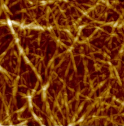
(4) REVIEW ARTICLE. bioresources.com. 2000; Ruiz et al. 2000; Samir et al. 2004b, 2005; Schroers et al. 2004; Kvien et al. 2005; Ljungberg et al. 2005; Hamad 2006; Renneckar et al. 2006; Oksman and Sain 2006; Wang et al. 2006a; Abe et al. 2007; Marcovich et al. 2006; Petersson et al. 2007; Pu et al. 2007; van den Berg et al. 2007a,b; Ye 2007; Elazzouzi-Hafraoui et al. 2008). Indeed, electron micrographs of nanofibers obtained from tunicates show objects that resemble a cat’s whiskers in terms of straightness and the length-to-width ratio. Dimensions of about 8 to 20 nm in thickness and lengths sometimes in excess of 1 µm have been reported (Terech et al. 1999; Lima and Borsali 2004). Synonyms for “whiskers” have included “nanorods” (Dujardin et al. 2003), “rod-like cellulose microcrystals” (Lima and Borsali 2004), and “nanowires” (Podsiadlo et al. 2007; Shim et al. 2007). According to Elazzouzi-Hafraoui et al. (2008) it is common to observe crystalline nanocellulosic elements that are wider than the numbers cited above, and this can be attributed to lateral bonding between adjacent crystallites during biosynthesis. In any case, these cellulose (nano)whiskers can be devoid of chain folding and contain only a small number of defects. They have a very large modulus of elasticity, estimated to be around 130 GPa, and strength in the order of 7 GPa (Kroonbatenburg et al. 1986; Abe et al. 2007). Recently there has been increasing interest in materials consisting of larger numbers of cellulose nanofibers or fibrils that remain attached together for at least a portion of their length. Several methods have been proposed since the 1980s (Herrick et al. 1983; Turbak et al. 1983) to prepare and isolate these fibril materials, usually described as microfibrillar cellulose (MFC) (Svagan et al. 2007) and nanofibrillar cellulose (NFC) (Netravali et al. 2006). As can be inferred from the above explanations, variations in cellulose raw material, pre-treatment, and disintegration or deconstruction of the fiber cell wall will lead to a broad spectrum of structures and ensuing nomenclature. This includes “nanocellulose composites” (Ye 2007), “nano-scale fibrillated cellulose” (Nakagaito and Yano 2004), “cellulosic fibrillar fines” (Luuko and Maloney 1999; Mosbye et al. 2002, Subramanian et al. 2008), etc. As noted by Wang and Sain (2007a), these are bundles of cellulosic nanofibers with a diameter ranging up to 100 nm and lengths generally greater than 1 µm. The high strength of nanofibrillar cellulose together with its potential economic advantages will offer the opportunity to make lighter, strong materials with greater durability (Wegner et al. 2005). Figure 1 shows an example of cellulosic fibrils formed into a paper-like structure. Finally, the term “cellulose aggregate fibrils” has also been used (Cheng et al. 2007; Lee et al. 2007). As implied by the word “aggregate,” though the component fibrils may be in the 1-100 nm range of widths, the fibrils have not been completely separated from each other. In the case of larger aggregate structures the term “microcrystalline cellulose” (MCC) has been generally applied to products such as those that have been used for many years for compounding of pharmaceuticals. Such products are typically derived by sulfuric acid treatment of bleached kraft wood fibers, followed by washing and drying. As noted by Bondeson et al. (2006b), the spray-drying process used for most MCC products generally results in reagglomeration of smaller cellulosic crystalline domains, and the agglomerates become strongly attached together through hydrogen bonding.. Hubbe et al. (2008). “Cellulosic nanocomposites, review,” BioResources 3(3), 929-980.. 932.
(5) REVIEW ARTICLE. bioresources.com. MCC particles may range in shape from “stubby” to “fibrillar,” however, the minimum dimension of a MCC particle usually is in excess of 1 µm.. Figure 1. Example of cellulosic nanofibers formed into a paper-like structure. Image has dimensions of 1 μm on each side (photo courtesy of M. Österberg, Helsinki University of Technology). Information about the shape, mean size, and distribution of size of cellulosic nanoparticles can be obtained by such methods as transmission electron microscopy (TEM), scanning electron microscopy (SEM), atomic force microscopy (AFM), or light scattering (Elazzouzi-Hafraoui et al. 2008). Braun et al. (2008) showed that a multi-angle laser light scattering (MALLS) method can be especially effective for quantifying such data; by such means it is possible to sample a large number of particles and obtain good statistical information about distributions in size and in the ratio of length to width. The TEM method is highly regarded for showing features of individual cellulosic nanoelements (Dufresne et al. 2000; Wang and Sain 2007a; Elazzouzi-Hafraoui et al. 2008). TEM methods can offer superior resolution, while avoiding the broadening effects that can be caused by AFM probe geometries (Kvien et al. 2005). Cellulosic Chemical Features, vs. their Incorporation into Composites Cellulose’s chemical characteristics provide it with a rich variety of options for chemistry and engineering for many material applications. Cellulose’s structure is based on a 180o turn-screw ß-1,4-glucopyranoside cellulose polymeric chain that gives rise to various crystalline domain formations that are considered allomorphs (see Saxena et al. 1994). These domains possess very high strength, approximately on the order or greater than a comparable structural steel sample. This intrinsic strength is available in the fundamental domains, the nanocrystals, which can be obtained upon a variety of acid hydrolyses to yield rod-like crystals (Dujardin et al. 2003). These nanocrystals are able to provide reinforcement in a variety of composites (see Grunert and Winter, 2000; Favier et al. 1997; Azizi Samir et al. 2004b-d); yet, a problem is that failures in a. Hubbe et al. (2008). “Cellulosic nanocomposites, review,” BioResources 3(3), 929-980.. 933.
(6) REVIEW ARTICLE. bioresources.com. composite with these materials are really due to weak boundary layer interactions, especially between polar (cellulose) and non-polar components. Thus, chemical modification schemes are necessary, which can generally be done to the cellulosic portion followed up by cross-linking (see McCreight et al. 2006). Cellulose can easily accommodate hydrophobic appending chains to overcome adverse interactions with nonpolar composite matrices. Moreover, the high melting temperature of the cellulose nanocrystals can positively affect the thermal transition properties of these appending chains, a very attractive feature for designing materials that need to perform at high temperatures. Likewise, the high hydrophilicity of cellulose is sometimes a disadvantage in certain applications; thus, a variety of surface modification strategies are available such as coating them with surfactants (Heux et al. 2000) or grafting hydrophobes onto them (Grunert and Winter 2002). Finally, cellulosic nanocrystals possess three unique molecular characteristics of significance that allow them to act as scaffolds for composite applications: cellulose nanocrystals are rigid molecular rods and can impart significant strength and directional rigidity to a composite; cellulose nanocrystals have an embedded polymeric directionality (terminal reducing glucose endgroups) that can be preferentially exploited for building new nanocomposites; and finally, cellulose nanocrystals have an etched molecular pattern on their surfaces composed of primary hydroxyl groups at the C6 position, which can also be exploited for grafting specific hydrophobes or hydrophiles. . Source Materials for Ultra-Fine Cellulosic Elements Wood as a source of nano-cellulose structures In principle, almost any cellulosic material could be considered as a potential source for the isolation of nano-sized cellulosic structures. In practice, researchers have shown clear preferences. Commonly studied source materials have included not only wood, but also crop residues, sugar cane bagasse, bacterial cellulose, tunicates, and a few other kinds of relatively pure cellulose, such as regenerated cellulose. Because of its great abundance, wood has been considered as an attractive starting material for making nanomaterials. However, isolation of cellulosic nanofibers, crystalline whiskers, or other relatively pure cellulosic structures having minimum dimensions in the range of 1-100 nm usually requires a multi-stage process involving vigorous chemical and/or mechanical operations. For example, researchers at the University of Toronto have pioneered an approach that combines chemical treatment, mechanical refining, homogenization, and crushing of the water-soaked material in the presence of liquid nitrogen (Bhatnagar and Sain 2005; Chakraborty et al. 2006a,b). Rather than starting directly with wood itself (Panaitescu et al. 2007a), most researchers have started by using partially or almost completely purified versions of wood, e.g., microcrystalline cellulose (MCC) (Laka et al. 2000; Wang and Ding 2004; Bondeson et al. 2006a,b; Ioelovich and Leykin 2006; Oksman et al. 2006; Marcovich et al. 2006) or bleached kraft pulp, from which most of the lignin and substantial amounts of hemicellulose already have been removed (Bhatnagar and Sain 2005; Orts et al. 2005; Ioelovich and Leykin 2006; Petersson and Oksman 2006a,b; Stenstad et al. 2008). MCC usually is produced by hydrolyzing bleached kraft pulp with sulfuric acid (Ioelovich and. Hubbe et al. (2008). “Cellulosic nanocomposites, review,” BioResources 3(3), 929-980.. 934.
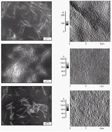
(7) REVIEW ARTICLE. bioresources.com. Leykin 2006), and this same procedure is generally employed by researchers who want to make cellulosic nanofibers “directly” from kraft fibers (Bhatnagar and Sain 2005; Orts et al. 2005; Stenstad et al. 2008). Lu et al. (2006) pioneered the use of regenerated cellulose (also a byproduct of bleached kraft pulp) for the production of nanofibers, using an acid hydrolysis similar to the process used by researchers who use MCC as starting material. Agricultural byproduct materials Crop residues used as sources for production of nano-sized cellulose structures have included wheat straw (Helbert et al. 1996; Dufresne et al. 1997; Alemdar and Sain 2008a,b), potato tubers (Dufresne et al. 2000), flax (Biagiotti et al. 2004; Cao et al. 2007), sugar beet pulp (Dinand et al. 1999; Leitner et al. 2007); hemp (Wang et al. 2007a), rutabaga (Bhatnagar and Sain 2005), swede root (Bruce et al. 2005), sisal (de Rodriguez et al. 2006; Moran et al. 2008), soybean stock (Wang and Sain 2007a,b), and banana rachis (Zuluaga et al. 2007). Cotton also has been used as a source material (Lima and Borsali 2004; Montanari et al. 2005; Elazzouzi-Hafraoui et al. 2008), taking advantage of its relatively low lignin and hemicellulose content, in comparison to wood. Figure 2 shows examples of cellulose nanocrystals, and the corresponding AFM images of films prepared from those nanocrystals. Animal cellulose The relative purity, as well as the potential to produce nearly defect-free cellulosic “whiskers” were some of the reasons that certain animal products became among the first materials studied as a potential source of cellulosic nanomaterials for use in composites (Favier et al. 1995a,b). Subsequent studies have evaluated the use of tunicate-derived whiskers in a variety of ways (Favier et al. 1995a,b, 1997; Terech et al. 1999; Angles and Dufresne 2000, 2001; Ruiz et al. 2001; Mathew and Dufesne 2002 ; Dufresne 2003, 2006 ; Schroers et al. 2004 ; Azizi Samir et al. 2004a,b, 2006; Kimura et al. 2005; Yuan et al. 2006; Podsiadlo et al. 2007; van den Berg et al. 2007a,b; Elazzouzi-Hafraoui et al. 2008). Bacterial cellulose Other researchers have employed bacterial cellulose as a starting material (Nakagaito et al. 2005a,b; Orts et al. 2005; Yano et al. 2005; Nogi et al. 2005, 2006a,b; Roman and Winter 2006; Nakagaito and Yano 2006; Millon and Wan 2006; Wan et al. 2006a,b, 2007; Gea et al. 2007; Ifuku et al. 2007; Juntaro et al. 2007; Yano et al. 2008). As noted by Sun et al. (2007), some of the bacterial cellulose has widths already in the nanometer range, even before processing. Brown and Laborie (2007) took advantage of this fact when they bypassed a purification step, forming a nanocomposite from a cellulose-containing bacterial mixture and polyethyleneoxide (PEO). Nanocellulose from bacterial sources has been especially popular among researchers focusing on medical applications, such as the use of a cellulosic “scaffold” to direct the growth of tissue or bone (Czaja et al. 2007). It is notable that Guhados et al. (2005) employed bacterial cellulose when they carried out a rare evaluation of the bending modulus of individual nanofibers.. Hubbe et al. (2008). “Cellulosic nanocomposites, review,” BioResources 3(3), 929-980.. 935.
(8) REVIEW ARTICLE. bioresources.com. Figure 2. Left: Transmission electron micrographs (TEM) of cellulose nanocrystals derived from ramie (top), cotton (center) and sisal (bottom) (courtesy of Dr. Y. Habibi in NCSU); Right: Atomic force microscope (AFM) images of films prepared from each set of nanocrystals (courtesy of I. Hoeger and X. Liu at Rojas’s lab in NCSU).. Organization of the Article The remaining sections of this review article are organized according to the following logical sequence: As a first step in the preparation of cellulosic nanocomposites it is necessary to liberate cellulosic nano-elements from source materials such as wood or agricultural residues. Next, there can be advantages to modifying the. Hubbe et al. (2008). “Cellulosic nanocomposites, review,” BioResources 3(3), 929-980.. 936.
(9) REVIEW ARTICLE. bioresources.com. surfaces of the cellulosic component, before making a composite material. Third, a variety of approaches have been used in the forming, extruding, or assembling of nanocomposites. Once formed, nanocomposites have a variety of potential applications. A final section of the article deals with challenges that need to be faced as various forms of cellulosic nanocomposites become further developed and implemented.. ISOLATION OF CELLULOSIC NANO-ELEMENTS Background In their list of “priority activities,” the participants in the American Forest and Paper Association’s workshop (2005) listed “liberate nano-sized cellulosic fibrils” as their very first area of focus. Descriptions of some of the methods used to isolate cellulosic nano-elements (whiskers, fibrils, crystals, nano-fibers, etc.) from wood and other source materials have been reviewed (Azizi Samir et al. 2005; Oksman and Sain 2006; Ye 2007). In general terms it has been possible to identify a number of basic approaches to separating cellulosic materials into elements having at least one dimension in the 1-100 nm range, i.e. “nanoparticles” (Laskiewicz 2000). For simplicity, these will be categorized into chemical delignification (pulping and bleaching), mechanical diminution, chemical diminution, and dissolution. As will become clear from studies to be cited, though these optional ways to separate cellulosic materials will be considered here separately, they often can be used sequentially or in combination. In particular, the pulping and bleaching operations to be described next are often used as a kind of pretreatment before further modification of wood to obtain cellulosic nano-elements. Chemical Pulping and Bleaching of Wood Lignin impedes separation of wood into its component fibers, so it is reasonable to consider delignification methods as promising initial steps for the preparation of nanocellulose items, such as fibrils and crystals (Moran et al. 2008). Because excellent descriptions of pulping and bleaching processes are available (for instance Smook 1992; Hon and Shiraishi 2001), only a summary will be given here. The kraft pulping process is the most commonly used method of lignin removal, especially when the fibers are to be used for papermaking. Wood chips are treated under pressure with a hot solution of NaOH and Na2S in a pressurized vessel called a digester. The lignin component of the wood becomes progressively depolymerized, chemically substituted, and eventually solubilized. To a lesser degree kraft pulping causes hydrolysis and solubilization of hemicellulose, further reducing the yield of the process. Most of the cellulose is preserved. An abrupt reduction in pressure as the contents of the digester are discharged causes the wood chips to become substantially dispersed as individual fibers. Depending on the extent to which the kraft process is continued, the resulting fibers can have lignin contents in the range of roughly 1 to 10% of the total dry mass, and the color can be generally described as brown or tan, depending on the yield.. Hubbe et al. (2008). “Cellulosic nanocomposites, review,” BioResources 3(3), 929-980.. 937.
(10) REVIEW ARTICLE. bioresources.com. Bleaching If one’s goal is to obtain colorless cellulosic nanomaterials, and especially if a high degree of crystallinity is desired, then it can make sense to subject kraft fibers to a sequence of bleaching treatments. The reason that the kraft pulping operation is not just continued, with higher levels of chemical or more time, is that the kraft cooking process is not sufficiently selective, and there would be excessive breakdown of the polysaccharide portion of the fibers. Oxygen delignification is becoming increasingly popular as an initial stage of bleaching, due to the fact that the bleach effluent can be included in the kraft chemical recovery cycle, allowing any dissolved lignin or carbohydrate byproducts to be incinerated, with the recovery of energy. Chlorine dioxide is a yet more powerful oxidizing agent, and it is also a more highly selective bleaching agent, capable of solubilizing the relatively intractable residual lignin; however, the solubilized material from a ClO2 stage cannot be sent to the kraft recovery boiler. After the acidic ClO2 treatment it is usual to extract the fibers with NaOH solution, often in combination with the addition of some hydrogen peroxide, causing much of the oxidized lignin to be removed from the fibers. Subsequent pulp bleaching stages can include treatments of the fibers with more ClO2, H2O2, sodium hypochlorite, ozone, peracetic acid, or a variety of other options. The remaining fibers, after pulping and bleaching, will consist mostly of polysaccharides, especially cellulose. The fiber length is typically about 3 mm in the case of softwood-derived fibers and closer to 1 mm in the case of hardwood fibers, and a typical length-to-width ratio is about 50:1 up to more than 100:1 in some cases. Results of work by Dinand et al. (1999) suggest that it can be a mistake to remove all of the “impurities” from cellulosic nanocrystals, especially if hemicellulose is considered as an impurity. These authors observed that residual hemicellulose and pectin in cellulosic material obtained from sugar beets helped to keep the suspension from coagulating. On the other hand, the nanocrystalls coagulated rapidly in aqueous suspension in cases where the hemicellulose and pectin had been removed by treatment with strong alkali. The effects of the hemicellulose and pectin can be attributed to their hydrophilic nature, their negative charge, and their contribution to steric stabilization (Stana-Kleinschek and Ribitsch 1998; Paananen et al. 2004; Tammelin et al. 2007). Suitability of cellulosic fibers for composite manufacture Though full-sized cellulosic fibers can be used in composites (Felix and Gatenholm 1991; Mwaikambo and Ansell 1999; Piejs 2002; Belgacem and Gandini 2005; Renneckar et al. 2006; Pasquini et al. 2006; Alvarez et al. 2007; Dominkovics et al. 2007), such products do not ordinarily fit the definition of nanocomposites. Cellulose fiber-containing composites can offer substantial improvements in strength and dimensional stability characteristics. To give one example, the laminated products commonly used for counter-tops and other decorated or plane furniture surfaces are noted for having much less change in dimension with changes in moisture exposure, compared to either the resin or the fiber portion of the structure, if used by itself (Adams 1980). Given the gains that can be achieved just by combining cellulosic fibers with a polymeric matrix, a question can be asked, “Why should anyone want to go through the additional effort required to create nanocomposites, the first step in which is the. Hubbe et al. (2008). “Cellulosic nanocomposites, review,” BioResources 3(3), 929-980.. 938.
(11) REVIEW ARTICLE. bioresources.com. painstaking separation of whiskers, fibrils, or crystals, etc., from the cellulose?” Two types of reasons can be offered. First, it is reasonable to expect that a composite structure at the nano-scale can provide additional property improvements and unique characteristics. In other words, it might be foolish to neglect the nanometer size range when attempting to build the most effective materials and structures. For instance, Okubo et al. (2005) showed that the presence of finely fibrillated cellulose was able to prevent the development of micro-cracks in a composite. A second set of reasons arises due to the inherent nature of macroscopic cellulosic fibers. The cellulose in typical wood-derived fibers can contain about 25 to 40% of non-crystalline material, i.e. the “amorphous regions” of the native cellulose (Alén 2000). This material renders the cellulose fibers quite susceptible to dimensional changes when the moisture changes. Even if the continuous phase of a cellulose fiber-filled composite is a water-hating plastic material, the cellulosic fibers that are used as reinforcing agents can be expected to allow moisture into the interior of the composite structure, eventually leading to decay and loss of strength. In principle it is possible to avoid such problems by using only non-porous crystalline cellulosic structures, and these are presently available only at the nano-scale. While the concepts summarized in the previous paragraph may be true in principle, one needs to be cautious when attempting to estimate likely performance benefits deriving from a nanocomposite structure. A review and analysis by Schaeffer and Justice (2007) revealed that the majority of nanocomposite structures that have been reported in the literature have much lower modulus of elasticity than would be expected theoretically, especially if one assumes a random distribution of filler elements. The effect was attributed to agglomeration of the filler particles, causing the cited authors to question whether typical “nanocomposite” structures truly deserve to be called “nano.” Mechanical Diminution Extensive separation of bleached kraft fibers into nanofibers (or “fibrils”) can be achieved if conventional refining methods are applied well beyond the levels typically used in preparing kraft fibers for papermaking (Wang et al. 2005, 2007a; Chakraborty et al. 2006a,b). Conventional refining is most often achieved by passing a 4-6% solids dispersion of fibers between rotating and stationary discs or cones having patterns of raised rectangular bars, separated by groove spaces. The progress of refining can be monitored by measuring the increased time required for water to drain by gravity through a pad of fibers that forms on a screen (TAPPI 1997). Refining also tends to increase the capacity of fiber walls to hold onto water, i.e. the water retention value, WRV (TAPPI 1981). Refining at conventional levels results in increasing wet-flexibility of the fibers, and also the lumens of fiber more readily collapse, yielding a more ribbon-like shape of the fiber. Meanwhile, progressive unraveling of the S1 and S2 sublayers of the fiber results in a fibrillated surface of refined kraft fibers. Such fibrils at fiber surfaces can be seen by light microscopy under suitable lighting conditions. Relatively large requirements of energy have been reported when refining practices are continued long enough to release a substantial proportion of the material as fibrils having widths in the nano-scale. For instance Nakagaito et al. (2004) observed significantly improved strength of composites only if kraft fibers had been passed 16 to 30 times through a refiner, and this was sufficient to completely fibrillate the cellulose.. Hubbe et al. (2008). “Cellulosic nanocomposites, review,” BioResources 3(3), 929-980.. 939.
(12) REVIEW ARTICLE. bioresources.com. For sake of comparison, typical papermaking processes often employ one to three passes through a refiner. In another study Chakraborty et al. (2005) found that up to 125,000 revolutions of a so-called PFI mill were required in order to convert bleached softwood kraft pulp into nano-fibers; this value represents roughly 50-100 times the amount of refining energy used in refining the same kind of pulp for papermaking. As noted by Cheng et al. (2007), these approaches, based on multiple applications of compression and shear on an individual of cellulosic fiber in a suspension, usually result in aggregates of nano-scale fibrils, rather than yielding separated fibrils or individual crystal domains. Another strategy by which to break up cellulosic fibers into nano-sized component structures involves passing the material through a small nozzle at very high pressure. Such homogenization has been used by many researchers, often in combination with other treatments (Nakagaito and Yano 2004; Bruce et al. 2005; Iwamoto et al. 2005; Ioelovich et al. 2006; Cheng et al. 2007; Leitner et al. 2007; Paakko et al. 2007; Wang et al. 2007a; Zuluguaga et al. 2007; Alemdar and Sain 2008; Stenstad et al. 2008; Wågberg et al. 2008). High intensity ultrasonic treatments (Lima et al. 2004; Bondeson et al. 2006a; Cheng et al. 2007; Paakko et al. 2007; Wang et al. 2008) generally have been reported to yield shorter, less fibrillar particles of nano-cellulose in some cases (Paakko et al. 2007; Wang et al. 2008), though thin whiskers were obtained by others, following sonification (Lima et al. 2004; Bondeson et al. 2006a). The term “cryocrushing” refers to a process in which water-swollen cellulosic material is immersed in liquid nitrogen, then crushed with a mortar and pestle. In the case of kraft fibers, this procedure has been found to be effective after refining, which promotes delamination and swelling (Chakraborty et al. 2005; Bhatnagar and Sain 2005; Janardnan and Sain 2006; Alemdar and Sain 2008). Evidently, brittle fracture of the nanofibers is made possible by the intense freezing, inducing brittleness, in combination with intense mechanical forces. Chemical Diminution Acid Hydrolysis Even in cases where researchers have used one or more of the mechanical treatments just described, they almost always combine or sequence such treatments with either acid hydrolysis or enzymatic treatments. Treatment with sufficiently strong acid can effectively break down the amorphous cellulose, thus liberating cellulosic nano-sized crystals into the suspension (Lima and Borsali 2004; Wang and Ding 2005; BeckCandanedo et al. 2005; Kimura et al. 2005; Orts et al. 2005; Bondeson et al. 2006a,b; Dufresne 2006; Lu et al. 2006; Cao 2007; Henriksson et al. 2007; Elazzouzi-Hafraoui et al. 2008; Moran et al. 2008). For instance Moran et al. (2008) treated sisal-derived cellulosic fibers with 60% H2SO4 at 45 oC for 30 minutes. Enzymatic treatment Analogously to the acid hydrolysis treatments just described, cellulase enzymes are expected to favor attack on the amorphous regions of cellulosic substrates. Henriksson et al. (2007) reported that such treatment made it easier to separate the material into microfibrillated cellulose. Janardhnan and Sain (2006) found that enzymatic treatment made it possible to achieve a smaller particle size range of cellulose,. Hubbe et al. (2008). “Cellulosic nanocomposites, review,” BioResources 3(3), 929-980.. 940.
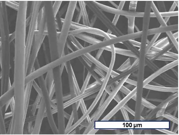
(13) REVIEW ARTICLE. bioresources.com. following high-shear refining. Paakko et al. (2007) found that by using a combination of enzymatic hydrolysis and mechanical shearing it was possible to liberate relatively long, rod-like cellulose units. Recently, a novel approach to study the dynamics of (cellulase) enzymatic activity was used to demonstrate the remarkable difference in the time required to hydrolyze amorphous and crystalline films of cellulose (Turon et al. 2008). Such difference in “diminution” susceptibility explains the principles used in the separation of crystalline and amorphous cellulosic components of the cell wall. Dissolution Solvent treatments Oksman et al. (2006) reported an innovative use of a solvent to swell microcrystalline cellulose, making it much more susceptible to separation into nanofibers. The solvent system was N,N-dimethylacetamide (DMAc) to which lithium chloride (LiCl) had been added. Nelson and Deng (2007) showed that it was feasible to generate cellulosic nanoparticles by adding a non-solvent to an agitated cellulose solution. Various researchers have reported the electro-spinning of cellulose solutions as a way to form extremely fine cellulose fibers or threads (Kulpinski 2005; Kim et al. 2006; Viswanathan et al. 2006; Han et al. 2008). The electrospinning process involves steady extrusion from concentrated polymer solution from metal syringe-type needle, under the influence of a strong direct current-induced electric field. Liang et al. (2007) explored the electrospinning of bi-functional or 2-component mixtures to obtain cellulosecontaining nano fibers for use in medical applications. Figure 3 shows an example of very fine cellulose acetate fibers produced by electrospinning.. Figure 3. Example of cellulose acetate fibers prepared by electro-spinning (courtesy of Dr. G. Montero at Rojas’ lab in NCSU).. Hubbe et al. (2008). “Cellulosic nanocomposites, review,” BioResources 3(3), 929-980.. 941.
(14) REVIEW ARTICLE. bioresources.com. Ionic liquids Gindl and Keckes (2005) partially dissolved microcrystalline cellulose, using an ionic liquid, and then cast the material into a film, which they identified as a nanocomposite. Kilpelainen et al. (2007) have suggested the use of ionic liquids to first dissolve cellulose, and then, due to changed conditions, to reprecipitate the material in a wide range of morphologies, including composite structures. Sui et al. (2008) formed cellulose nanofibers and nanoparticles by the spraying of an ionic liquid cellulose solution. Kadokawa et al. (2008) used an ionic liquid to partially disrupt the structure of cellulosic material, followed by a polymerization reaction in the continuous phase.. SURFACE MODIFICATION OF NANO-ELEMENTS Principles of Surface Modification Chemical compatibility between the filler material and the continuous matrix can be expected to play a critical role, both in the dispersion of the filler in the matrix material and in the development of satisfactory adhesion between the two phases. As was stated earlier, the surface of cellulosic materials tends to be incompatible with many of plastic materials that are most commonly considered in the production of composites, e.g. polyethylene, polypropylene, styrene, etc. In addition, the tendency of cellulosic fibers to absorb water can be considered to be undesirable in many potential applications of composites. Various authors have reviewed research related to chemical modifications, especially those by which macroscopic cellulosic fibers can be rendered less hydrophilic and more miscible with oleophilic matrices (Bledzki et al. 1998; Lu et al. 2000; Eichhorn et al. 2001; Mohanty et al. 2001; Lindström and Wågberg 2002; Belgacem and Gandini 2005; Jacob et al. 2005). It is often beneficial to increase the effective surface area or to remove loosely bound or waxy materials from the fibers (George et al. 2001; Mohanty et al. 2001). The free energy of the surface also can be increased by application of corona discharge (Belgacem and Gandini 2005) or other chemical treatments. Cellulosic surfaces can be derivatized by various direct reactions involving the hydroxyl groups. Esterifications and silanations are mostly commonly used in preparing cellulosic materials for use in composites, though many other treatments have been applied less commonly (Mohanty et al. 2001; George et al. 2001; Belgacem and Gandini 2005). Further options include (a) the use of bifunctional reagents, which provide another reactive functionality, in addition to the part of the molecule that reacts with the fiber surface, (b) activation of the surface, followed by polymerization, such that bonds are formed between the phases, and (c) organometallic chemistry (Belgacem and Gandini 2005). As noted by Mohanty et al. (2001), there often can be an optimum level of fibermatrix adhesion, beyond which further derivatization of the cellulosic fibers may make the final product less suitable in a given application. The existence of such optimum levels of fiber surface modification can be explained in at least two ways. On the one hand, it can be important to verify that a treatment regime designed to modify the surface does not, in fact, damage the structure of a cellulosic material (Baiardo et al. 2002;. Hubbe et al. (2008). “Cellulosic nanocomposites, review,” BioResources 3(3), 929-980.. 942.
(15) REVIEW ARTICLE. bioresources.com. Gousse et al. 2004; Morales et al. 2006; Nogi et. al. 2006a,b; Megiatto et al. 2007). On the other hand, it may be possible to optimize such attributes as the modulus of elasticity, strength to breakage, and impact resistance, etc., by controlling the degree to which included structural elements are bonded to the matrix of a composite (George et al. 2001; Chauve et al. 2005). It can be important to achieve the right balance between flexibility and rigidity, depending on the end-use of a composite material. Jacob et al. (2005) have provided a good overview of ways in which the adhesion between cellulosic fibers and polymer matrices can be controlled and also evaluated. Wettability and Adhesion In principle, in order for a strong bond to form between two phases, one of which is initially in a liquid state, it is first necessary that the liquid phase be able to spread over the solid surface, creating intimate contact. The ability of liquids to spread over and ultimately to bond to solid surfaces often can be predicted by measurements of contact angles (Felix and Gatenholm 1991; Joly et al. 1996; Trejo-O’Reilly et al. 1998; Gassan et al. 2000; Singh et al. 2000; Vilaseca et al. 2005; Pasquini et al. 2006; Averous 2007; Girones et al. 2007a; Heng et al. 2007; Megiato et al. 2007). Such methods become quite challenging even when applied to wood-derived fibers, due to their small size and irregularities (Miller et al. 1983), so it is necessary consider other possible methods for evaluation of the surfaces of even more finely divided materials. The inverse gas chromatography (IGC) method appears to be well suited to such applications (Joly et al. 1996; Trejo-O’Reilly et al. 1998; Matuana et al. 1998; Kazayawoko et al. 1999; Zafeiropoulos et al. 2002a,b; Heng et al. 2007). However, a literature search did not reveal any cases where IGC methods had been used in conjunction with nano-sized cellulosic structures. Though wettability is necessary for strong adhesion at an interface, having good wettability is not necessarily sufficient for adhesion. Considering the case of cellulosic composites, Tze et al. (2006) provided an especially good description of how solubility parameters, acid-base interactions, and the kinetics of diffusion processes all can play critical roles in bond development. Briefly stated, solubility parameters have been developed by evaluating whether pairs of pure substances, at least one of which is a liquid, can form a single phase when they are mixed together. Though the results of such tests often can be predicted based on the types and amounts of different functional groups that constitute each of the substances, the underlying mechanisms usually involve the capabilities of each substance to interact by London dispersion forces and by polar interactions (Megiatto et al. 2007). Matuana et al. (1998) made an attempt to verify the further expectation (see Tze et al. 2006) that interfacial adhesion at cellulosic surfaces ought to be enhanced by interactions between acidic and basic groups; however, in the cases that they considered, such effects were found to be less important in comparison to the development of covalent bonds. Reactions to Form Ionic Groups at Cellulosic Surfaces Simple oxidation of the fiber surface can be a practical way to generate carboxylic acid groups. For example Couto et al. (2002) used an oxygen plasma to treat sisal fibers and enhance their interaction with polypropylene when formed into composites. Notably. Hubbe et al. (2008). “Cellulosic nanocomposites, review,” BioResources 3(3), 929-980.. 943.
(16) REVIEW ARTICLE. bioresources.com. in that study even better results were achieved when the plasma treatment was applied to the matrix material before compounding, making the polypropylene more hydrophilic, and thus more compatible with the cellulosic surfaces. Corona discharge is a common means to create such effects (Gassan et al. 2000). Morales et al. (2006) used plasma treatment as part of a procedure to graft polystyrene to the cellulose surface. Sulfonation Treatment of cellulose fibers with moderately concentration sulfuric acid, which is a common step in the preparation of microcrystalline cellulose (MCC), typically results in partial sulfonation of the cellulosic surfaces (Lima and Borsali 2004; Beck-Candanedo et al. 2005). In fact, the colloidal stability of aqueous suspensions of MCC prepared in this manner (Beck-Candanedo et al. 2005) has been attributed to double-layer repulsion forces induced by sulfonic acid groups at the surfaces of the particles (Lima and Borsali 2004). Carboxylation Cellulosic surfaces can be rendered much more hydrophilic by treatments to form carboxylic acids. The surfaces also are much higher in negative charge, as long as the pH is above about 3.5 so that the groups are in their conjugate base forms, as carboxylates. In addition to promoting a stable suspension in aqueous solution, a the process of carboxymethylation was cited earlier as a way to promote the breakup of cellulosic fibrous material to its nano-elements (Wågberg et al. 2008). These authors showed, however, that the colloidal stability of the resulting suspensions of nanofibers was very sensitive to adjustments in pH and salt concentrations. In addition, the highly negatively charged nanofibers interacted strongly with oppositely charged polyelectrolytes, and it was possible to form polyelectrolyte multilayers on the nanofibers. An especially effective way to induce controlled oxidation of cellulosic surfaces, for purposes of creating carboxyl groups, involves treatment with the 2,2,6,6tetramethylpiperidine-l-oxyl radical (TEMPO) (Montanari et al. 2005; Saito and Isogai 2005; Saito et al. 2007). Habibi et al. (2006) performed TEMPO-mediated oxidation of cellulose whiskers that were obtained from HCl acid hydrolysis of the animal cellulose tunicin. They showed that with a degree of oxidation of up to 0.1 the samples kept their initial morphological integrity and native crystallinity, but at their surface the hydroxylmethyl groups were selectively converted to carboxylic groups, thus imparting a negative surface charge to the whiskers. When dispersed in water these oxidized whiskers did not flocculate, and their suspensions appeared birefringent. Saito et al. (2007) also found that the cellulose fibers derivatized using a similar way could be readily converted into nanofibers by mechanical treatment. Strong electrostatic repulsion between the resulting negatively charged nanofibers, in each of the cited studies, caused the aqueous nanofibers suspensions to by highly stable. Maleic anhydride (MAH) and succinic anhydride also have been used to treat cellulosic materials (Roberts and Tatham 1992; Hubbe et al. 1999; Mishra and Naik 2005; Nenkova et al. 2006; Kamel et al. 2008; Stenstad et al. 2008). For instance, such an approach has been used to induce negative charges on the surfaces of microfibrillated cellulose (Kamel et al. 2008; Stenstad et al. 2008). Though it is possible to carry out such. Hubbe et al. (2008). “Cellulosic nanocomposites, review,” BioResources 3(3), 929-980.. 944.
(17) REVIEW ARTICLE. bioresources.com. reactions by heating cellulose fibers in the presence of dry MAH, it has been found that conditions may have to be controlled carefully to avoid undesired embrittlement of such fibers (Hubbe et al. 1999). Researchers have demonstrated improved composite formation of MAH-treated cellulosic materials with polyolefins in certain cases (Mishra and Naik 2005; Nenkova et al. 2006; Kamel et al. 2008). A related approach has involved addition of MAH as a separate component during compounding of composites that contain suitable matrix copolymers and cellulosic materials (Shi et al. 2007). Grafting Grafting reactions also can be used to attach ionic groups to cellulosic or starch crystal surfaces (Matuana et al. 1998; Cai et al. 2003; Dou et al. 2006; Labet et al. 2007; Stenstad et al. 2008; Habibi and Dufresne 2008). Thus Cai et al. (2003) attached quaternary ammonium groups onto macroscopic cellulose fibers to be used in composites. Stenstad et al. (2008) reported the preparation of a wide range of treatments of microfibrillated cellulose, each starting with oxidation by cerium (IV), followed by a grafting reagent. By grafting with hexamethylene diisocyanate, followed by amines, it was possible to achieve positive ionic charges. Dou et al. (2006) prepared cellulosebased nanoparticles having negative charges, and the colloidal stability of their materials displayed unusually high and reversible responses to temperature. Derivatization to Create Hydrophobic Surfaces Acetylation/alkylation Ester formation is a popular way to impart a hydrophobic nature to cellulosic surfaces (Felix and Gatenholm 1991; Caulfield et al. 1993; Joly et al. 1996; Mwaikambo and Ansell 1999; Matsumura and Glasser 2000; Matsumura et al. 2000; Rong et al. 2001; Baiardo et al. 2002; Zafieropoulos et al. 2002a,b; Acha et al. 2006; Nogi et al. 2006a,b; Renneckar et al. 2006; Wang et al. 2006b; Yuan et al. 2006; Pasquini et al. 2006, 2008; Alvarez et al. 2007; Ifuku et al. 2007). Studies involving macroscopic cellulosic elements constitute most of the preceding list. Among the cited works, Matsamura and coworkers were the first to esterify the surfaces of cellulosic nano-particles, and they achieved high strength development. They attributed their promising results to a high compatibility at the macromolecular level between cellulose I domains in a matrix of partially esterified cellulose. Nogi et al. (2006a,b) and Ifuku et al. (2007) were among the first to use acetylated cellulosic nanofibers in the preparation of reinforced clear plastic. The use of alkenylsuccinic anhydride (ASA) by Caulfield et al. (1993) is intriguing, since the same chemical is frequently added to paper machine systems to impart hydrophobicity to paper during the drying process; a similar process was used later by Yuan et al. (2006) for the treatment of cellulosic whiskers. Other types of chemical derivatives have been demonstrated; however, once again most work has involved macroscopic cellulosic fibers. Isocyanate coupling agents can be considered as an alternative to esterifying agents, since they also can form covalent bonds to organic materials having surface hydroxyl groups. Girones et al. (2007b) described application of such a system to improve the compatibility of cellulose in polystyrenebased composites. In the system described, the reaction to the cellulosic surfaces was. Hubbe et al. (2008). “Cellulosic nanocomposites, review,” BioResources 3(3), 929-980.. 945.
(18) REVIEW ARTICLE. bioresources.com. able to take place during the compounding of the composite (see later discussion of compounding). Gou et al. (2004) demonstrated a two-step process, the first step of which was to esterify the cellulose surface with methacrylic anhydride. The unsaturated groups thus grafted onto the surface were subsequently able to participate in a polymerization process of styrene to form grafted polystyrene. Vilaseca et al. (2005) achieved a similar effect, starting with creating ester bonds between jute fibers and unsaturated fatty acids. The unsaturated groups were able to take part in subsequent free-radical polymerization reactions. Treatment of cellulosic surfaces with maleic-anhydride-modified polyolefins is another approach that has been demonstrated for various sizes of cellulosic filler elements (Felix and Gatenholm 1991; Joly et al. 1996; Gauthier et al. 1998; Trejo-O'Reilly et al. 1998; Snijder and Bos 2000; Joseph et al. 2002; Lai et al. 2003; Li and Matuana 2003; Lu et al. 2002, 2005; Nair and Thomas 2003; Qiu et al. 2004; Ljungberg et al. 2005; Sain et al. 2005; Vallejos et al. 2006; Chowdhury and Wolcott 2007; Correa et al. 2007; Kim et al. 2007; Kumar and Singh 2007; Mechraoui et al. 2007; Shi et al. 2007; Wang and Sain 2007c; Gu and Kokta 2008). By suitable choice of the polyolefin, the cellulosic surfaces prepared in this way can be designed for near-ideal compatibility with a wide range of matrix polymers. Of the preceding list, only the following studies involved nanocomposites (Ljungberg et al. 2005; Sain et al. 2005; Wang and Sain 2007c). Successful compounding with the chemicals just described requires that the cellulosic elements become well mixed with the matrix polymer, but without excessive duration or temperature heating, so as to avoid thermal degradation. Based on these principles, maleated polyolefin can be added to a dry mixture of unsubstituted polyolefin and cellulosic material, and then the reaction with the cellulosic surfaces can take place during compounding (Qiu et al. 2004a,b, 2005, 2006; Mutje et al. 2006; La Mantia and Morreale 2007; Mechraoui et al. 2007). Qui et al. (2004a) showed that it was possible to achieve a higher density of ester bonds, as well as stronger interfacial adhesion, by ballmilling the cellulose and the maleated polyolefin materials together prior to their heating and extrusion. Despite the reasonableness of the mechanisms described in this paragraph, a study by Kazayawoko et al. (1997, 1999) failed to detect any covalent reaction between maleated polypropylene and cellulosic surfaces under conditions that were typical for the formation of composites. Maldas and Kotka (1991) described a related method in which unmodified MAH was added to a mixture of polystyrene and sawdust before extrusion of a composite. In principle, the improved compatibility with unsaturated polyolefin might be attributed to a free-radical reaction with the C=C double bonds in the carboxylated ester groups that result from reaction of MAH with OH groups at the cellulosic surfaces (Marcovich et al. 1996). Further work by the same research group (Marcovich et al. 2005) concluded, however, that the improvements in composite properties were probably attributable just to improved wettability of the cellulosic surfaces by an unsaturated matrix polymer. Some authors have described the use of MAH-modified polypropylene and related chemicals during preparation of matrix copolymers in order to enhance their compatibility with cellulosic filler material (Zhang et al. 2002; Bullions et al. 2004). Strictly speaking, such should not be included in a discussion of “surface modification of. Hubbe et al. (2008). “Cellulosic nanocomposites, review,” BioResources 3(3), 929-980.. 946.
(19) REVIEW ARTICLE. bioresources.com. nano-elements.” However, such a treatment is very closely related chemically to the systems just described. Silane treatments Silane-based chemicals can be used to attach a wide range of functional groups onto the surfaces of cellulosic fibers. Numerous studies have dealt with the modification of cellulosic materials with silanes to improve their performance when used in composites (Bledzki and Gassan 1996; Singh et al. 1996; Matuana et al. 1998; Gassan et al. 2000; Singh et al. 2000; Rong et al. 2001; Abdelmouleh et al. 2002, 2005; Nair and Thomas 2003; Pothan and Thomas 2003; Gousse et al. 2004; Kuan et al. 2006; Paunikallio et al. 2006; Roman and Winter 2006; Girones et al. 2007a; Li et al. 2007; Panaitescu et al. 2007b; Pothan et al. 2007; Wang et al. 2007b). Of the preceding list only the studies by Gousse et al. (2004), Roman and Winter (2006), and Panaitescu et al. 2007b involved cellulosic nanocomposites. Lu et al. (2000) described forty different types of coupling agents that might be considered for such applications. The likely mechanism of silanation “coupling” reactions has been described by Castellano et al. (2004). In the strict absence of water, SiOR groups apparently do not react with cellulosic hydroxyl groups, although they do react with lignin’s more acidic phenolic hydroxyls. Moisture can lead to partial hydrolysis of the silane, rendering it reactive with the cellulosic hydroxyl groups, as long as the temperature is high enough, e.g. 80 oC. Roman and Winter (2006) showed that the presence of silylated cellulosic nanocrystals affected the crystallization of the matrix polymer, decreasing the heat capacity, and increasing the composite stiffness. The relative scarcity of surface derivatization studies involving cellulosic nanoelements, as noted in the preceding paragraphs, is possibly due to the short timespan during which cellulosic nanocomposites have been considered. Presumably it is only a matter of time before reactions that have been demonstrated in the case of macroscopic cellulose filler elements become applied to cellulosic nanocrystals, highly fibrillated cellulose, etc. Additional work will be needed to determine whether surface derivatization reactions can be carried out cost-effectively with nano-cellulose, and also that the resulting mechanical or thermal stability properties will be satisfactory. Surface Modification by Adsorption Surfactants The easiest way to modify the characteristics of cellulosic surfaces suspended in water is with water-soluble substances having an affinity for surfaces, i.e., “surfactants.” It must be admitted from the start that such “modifications” generally are not permanent; most surfactants can be removed from surfaces in a reversible manner, assuming that one uses enough rinse water. Nevertheless, a variety of researchers have reported that surfactant addition improved the compatibility between cellulosic solids and matrix polymers in the formation of composites (Gradwell et al. 2004; Lima and Borsali 2004; Ljungberg et al. 2005, 2006; Bondeson and Oksman 2007a; Petersson et al. 2007; Kim et al. 2008). It is proposed that the hydrophilic head group of the surfactant adsorbs on the cellulose surface whereas its hydrophobic tail finds proper solvency conditions in the matrix, thus deterring aggregation of the cellulose inclusions via steric stabilization. The. Hubbe et al. (2008). “Cellulosic nanocomposites, review,” BioResources 3(3), 929-980.. 947.
(20) REVIEW ARTICLE. bioresources.com. reasons for improved composite properties, in such cases, may include not only better wettability and adhesion between the phases, but also the possibility of more uniform distribution of the cellulosic materials within the matrix. Even though surfactant treatments are often regarded as being inexpensive, the very high surface area per unit mass of nano-cellulosic material can imply a rather high addition level, as well as considerable cost of the surfactant (Dufresne 2006). Treatment of cellulosic surfaces with polyelectrolytes Rather irreversible adsorption onto cellulosic surfaces can be achieved by use of cationic polyelectrolytes, as long as their molecular mass is sufficiently high (Wågberg 2000). Renneckar et al. (2006) described strategies based on polyelectrolyte adsorption as being one of the three ways of improving the properties of cellulose-reinforced composites (in addition to surface derivatization of the cellulose and chemical reactions designed to take place during extrusion of composites). The approach using polyelectrolytes was called “bottom-up,” since it can involve the self-assembly of polyelectrolytes onto the cellulose; in other words, the charged macromolecules arrange themselves into a contiguous layer, depending on their charge interactions. Related approaches could be considered for cellulosic nanocomposites. Work by de la Orden et al. (2007) was notable, since the researchers appear to have achieved a combination of ionic interactions and covalent bonding. Cellulose fibers were first treated with polyethylenimine (PEI), a well-known, highly cationic polyelectrolyte. Then the treated fibers were compounded into a polypropylene matrix, in the presence of heat and pressure. Infra-red spectroscopic analysis of the resulting composites indicated that the amines of the PEI had reacted with carbonyl and carboxyl groups, forming amide linkages under the conditions of extrusion. Ahola et al. (2008) showed that in the formation of a paper-like composite it can be advantageous to add a cationic polymer and cellulosic nanofibers sequentially, forming a “bilayer” on cellulosic fibers, instead of premixing the cationic polyelectrolyte and the nanofibers. The main strategies used in that study, as well as some closely related work related to papermaking dry-strength strategies (Hubbe 2005; Hubbe et al. 2005) could logically be applied also in the formation of cellulosic nanocomposites. Multilayers Particularly impressive gains in bonding properties, as well an unique optical effects can be achieved by careful application of oppositely charged polyelectrolytes, gradually building up multilayers on surfaces of interest. Such treatments have been applied to the treatment of cellulosic fibers (Wågberg et al. 2002; Ding et al. 2005; Lvov 2005; Agarwal et al. 2006; Lvov et al. 2006; Zheng et al. 2006; Xing et al. 2007; Wågberg et al. 2008). Initial efforts in this area began with the work of Aksberg and Ödberg (1990) who reported the adsorption of an anionic polyacrylamide on cellulosic fibers with pre-adsorbed cationic polyelectrolytes. The work by Ding et al. may have been the first time that this approach has been used in the case of cellulosic fibers having nanometer-range fiber widths. Podsiadlo et al. (2005, 2007), Cranston and Gray (2006), and Holt et al. (2007) employed a related approach in which cellulosic nanofibers played the role of “anionic. Hubbe et al. (2008). “Cellulosic nanocomposites, review,” BioResources 3(3), 929-980.. 948.
(21) REVIEW ARTICLE. bioresources.com. polyelectrolyte” in a multilayer deposition scheme. Likewise, Shim et al. (2007) introduced the strategy of using a Langmuir-Blodgett film method to build up wellstructured alternating layers of polyelectrolyte and cellulosic whiskers, having good lateral organization.. FORMING, COMPOUNDING, OR ASSEMBLY The great majority of reported cellulose-containing composites have been prepared either by mixing of water-compatible materials or by extrusion with waterimmiscible plastic matrix material. Lu et al. (2000) came up with the following four categories of methods used to form composites: compounding, blending, soaking, and spraying. Each of these main approaches provides many challenges. The filler material needs somehow to become well dispersed in the matrix material, and also there needs to be good wetting and adhesion at the phase boundaries. At the same time, as noted by Mohanty et al. (2001), care must be taken not to unduly damage the filler material in the process of preparing the composite. Further challenges can be due to the moisture absorption by most cellulosic materials, and their tendency to swell when wetted (Bledzki et al. 1998; Piejs 2002). As suggested by Yu et al. (2006), the hydrophilic nature of cellulose may point to a greater likelihood of success in development of environmentally friendly composites, based mainly on water-miscible materials. Results of work by Mathew and Dufresne (2002) suggest that the presence of cellulosic nanostructures during preparation of a nanocomposite has the potential to profoundly affect the properties of matrix polymer segments. To achieve this demonstration, sorbitol nanocomposites were prepared with tunicin whiskers. After drying, the nanocomposites were conditioned at various relative humidities. The glass transition temperature increased as the content of whiskers was raised up to the range 1015%, and thereafter it decreased again. Thus it would appear that the cellulosic nanoelements, as long as they were well dispersed in the matrix, had a sufficient influence on the matrix polymer that its glass transition point shifted. Uniformity of mixing Several studies have provided evidence of the importance of uniform mixing of reinforcing elements within the matrix material of a composite formulation (Ljungberg et al. 2005, 2006; Peterson et al. 2007; Wang and Sain 2007a). Mathew et al. (2006) likewise observed poor strength characteristics resulting from a formulation that was believed to provide poor distribution of the cellulosic nano-elements. In contrast, Juntaro et al. (2007) were able to achieve directional differences in the strength of cellulosic nanocomposites in which the nano-elements were strongly aligned. Schaefer and Justice (2007) carefully reviewed the literature in the search for a relationship between the quality of dispersion of nano-elements and the resulting effects on the modulus of elasticity, in comparison to the unfilled matrix material; they came to the conclusion that almost all so-called nanocomposites have fallen far short of the most optimistic. Hubbe et al. (2008). “Cellulosic nanocomposites, review,” BioResources 3(3), 929-980.. 949.
(22) REVIEW ARTICLE. bioresources.com. expectations, and that the reason for their relatively poor performance can be attributed to large-scale agglomerates of the filler material. Optical characteristics can provide important clues regarding the orientation or uniformity of rod-like nanocrystals. For example, well-dispersed tunicate cellulose whiskers can show birefringence when they are well dispersed (Petersson et al. 2007; van den Berg 2007a,b). Percolation Scientists who have studied composites have long appreciated the importance of aspect ratio, i.e. the ratio of the length to the other dimensions of the filler material. Depending on the aspect ratio, there will be different limits as to how much cellulosic filler can be packed into a given volume. Percolation theory predicts a maximum enhancement in composite properties when there are just enough nanoparticles, if properly dispersed in the matrix material, to form a continuous structure (Favier et al. 1995a,b, 1997; Hajii et al. 1996; Helbert et al. 1996; Dufresne et al. 1997, 1999; Ruiz et al. 2000; Azizi Samir et al. 2004a; Ljungberg et al. 2005; Chakraborty et al. 2006a,b; de Rodriguez et al. 2006; Wang et al. 2006a; Chatterjee et al. 2007; Noorani et al. 2007). In other words, enhanced modulus and other strength properties are expected if each fibrous element in the composite, on average, is in contact with two more others. Thus, Chakraborty et al. (2006a) observed a 2.5-fold increase in stiffness when the content of microfibers in a polyvinyl alcohol matrix was increased to 5%, but further increases in fiber content did not help strength characteristics. The authors proposed that microfibers ought to have an aspect ratio of at least 50 in order to be highly effective, based on such considerations (Chakraborty et al. 2006b). Brechet et al. (2001) proposed that percolation effects can be quite dependent on both the shape and the inter-connectedness of the filler elements in a composite. Relatively rigid composite structures would be expected if one assumes that most of the filler elements are contacting their nearest neighbors, as has been implicitly assumed in most of the articles cited in the previous paragraph. Softer, but still significant effects can be expected, though, if the nearest filler elements interact only through their interactions with the matrix. To some extent it has been possible to account for the strength characteristics of nanocomposites by molecular modeling, combined with dynamic mechanical analysis (Chazeau et al. 1999a-c, 2000; Dufresne 2000; Chauve et al. 2005; Young and Eichhorn 2007). According to Dalmas et al. (2006), excellent adhesion between the matrix and the reinforcing elements can result in spectacular reinforcement effects, but such systems also are susceptible to irreversible damage if they are subjected to deformation. Hydrophilic / Aqueous Systems Various researchers have formed composite materials with cellulosic materials in hydrophilic matrix polymers. A commonly applied method is to cast a film, and then to allow it to dry by slow evaporation (Favier et al. 1995a,b, 1997; Hajii 1996; Dufresne et al. 1997, 1999, 2000; Ruiz et al. 2001; Angles and Dufresne 2000, 2001; Mathew and Dufresne 2002; Schroers et al. 2004; Bhatnagar and Sain 2005; Malainine et al. 2005; Orts et al. 2005; Petersson and Oksman 2006a,b; Roman and Winter 2006; Wang et al.. Hubbe et al. (2008). “Cellulosic nanocomposites, review,” BioResources 3(3), 929-980.. 950.
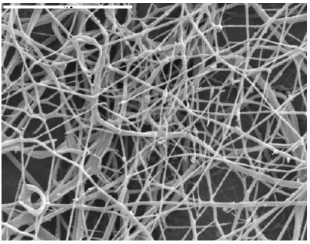
(23) REVIEW ARTICLE. bioresources.com. 2006a; Cao et al. 2007; Leitner et al. 2007; Pu et al. 2007; Svagan et al. 2007; Alemdar and Sain 2008a,b). Various modifications of the solution casting method have been employed. For instance Kvien and Oksman (2007) applied a strong magnetic field after solution casting to achieve strong alignment of cellulose whiskers in a polyvinyl alcohol matrix. Helbert et al. (1996) used freeze-drying to remove water after mixing components of a cellulose nano-composite. Yano et al. (2008) used solution casting and evaporation to prepare a binder-free nanocomposite comprising bacterial cellulose and silica nanoparticles. Nakagaito and Yano (2004) used high pressure to form their composites, following a practice similar to what is used industrially to prepare phenolic resin composites for furniture surfaces and other applications. Azizi Samir et al. (2004b) used a related approach; cellulose crystals were suspended in dimethylformamide (DMF) and ultrasonicated to obtain a stable suspension. The suspension was added to an unsaturated polyether resin, followed by evaporation and curing. Marcovich et al. (2006) likewise prepared a stable suspension of cellulose crystals in DMF as an initial step in formulation. They added the suspension to a mixture of polyol and isocyanate, thus forming a nano-reinforced polyurethane. Fahmy and Mobarak (2008), using an approach pioneered by Higgins and McKenzie (1968), dried bacterial cellulose nanomaterials in the presence of sucrose; by drying the material it this way it was possible to avoid collapse of the nanostructures and to preserve the high surface area and superabsorbent properties of never-dried cellulose of this type. Figure 4 gives an example of a composite material formed between cellulose nanocrystals and a hydrophilic polymer.. Figure 4. Example of nanocomposite formed between polyethyleneoxide (PEO) and cellulose nanocrystals. White horizontal bar at upper left indicates 5 μm (Photo courtesy of M. Peresin at O. Rojas’ lab in NCSU).. Hubbe et al. (2008). “Cellulosic nanocomposites, review,” BioResources 3(3), 929-980.. 951.
Figure
+2
Related documents
English, second language, ESL, ELL, vocabulary acquisition, word learning, reading, context,.. context clues, lexical inference, learning strategies, children’s
Mining the data recorded in firewall log files, our firewall products generate more than 200 activity reports, providing summary- level and comprehensive reports to present a
A shared discourse and programs of teacher training require awareness of historical contexts of interdisciplinary education, major terminology for distinguishing design
The first column shows the following summary graphs: the histogram plots of the order of drop over number of grids for the flow residuals L 2 norm (first row), the composite graphs
The motto was ―Learn and Train‖ (in Spanish, ―(In)fórmate‖), and it was dedicated to promoting information and encouraging training regarding PSIT.. Global E-Party en TISP
Remind students that when changing a fraction to a decimal, the top number is divided by the bottom number. What is the percent increase? Round to the nearest percent. What is the
This is based on the Novel Partial product Generation method using Higher radix-256 Booth encoding (NPGHB) which reduces the number of partial product rows by 8-fold.. Hence
In the present study, the women with the gestational hypertension in this index pregnancy were found to have a higher rate of metabolic syndrome that is 46.5%
