CFD APPROACH TO MODELING OF CORE-CONCRETE INTERACTION
Leonid Bolshov, Vladimir Chudanov
1. Nuclear Safety Institute (IBRAE), Russian Academy of Sciences, 52, B. Tulskaya, Moscow, 115191, Russia [email protected]
ABSTRACT
This paper deals with the development of the model for the SOCRAT severe accident system of codes for simulation of the heat and mass transfer problem in the pools containing multicomponent mixtures. This mathematical model is based on the Navier-Stokes equations with variable properties to account for a density change after concrete melting together with the heat transfer equation and equations which describes the diffusion of components between phases. The model is being developing to simulate the processes in the molten pool located in the lower head. Another significant application of the model is the processes in the core catcher and concreate cavity. The core catcher developed for VVER-1000 reactor contains sacrificial material containing components characteristic for the concretes. This provide a similarity between the interactions of corium with concrete and with sacrificial material which allow to use unified model. The capabilities of the code are demonstrated using using two sets of experimental data. The first test performed in the frame of OECD MASCA Project deals with the interaction of the metal phase with corium. The peculiarity of this test is the diffusion of metallic uranium from suboxidized corium to metal phase, which determine the density of both phases. The second test was used to validate the chemical interaction models in the molten pools. Use of multidimensional models allows simulation of important peculiarities of experiments.
INTRODUCTION
Core melt immobilization and coolability are the most significant issues for the justification of the NPP safety and accident management procedures. To simulate accident progression severe accident codes are being developed. The SOCRAT code [1] is intended to simulate severe accident phenomena using mechanistic approach for the constituting models. Multivariant melt progression scenarios, complicated mixtures formed during accident progression, insufficient knowledge of the phenomena involved determine the necessity of the development best estimate computer codes capable to account for significant peculiarities of severe accidents.
One of the important issues to be simulated is the phenomenon of molten pool behavior in the lower head and in the concrete cavity. Moreover development of new melt localization devices such as core catchers require detailed analysis of the processes to ensure containment integrity. From this point of view simulation of material interactions using the CFD approach allows detailed analysis of the heat transfer processes. This approach was realized in the CONV-2D and 3D codes [2]. Modern level of computer techniques and numeric methods allows using equations based on the first principles. The mathematical model based on the solving of the Navier-Stokes equations and energy equation for simulation of molten core-concrete interaction is described in [3].
The developed software corresponds to modern level of development of computers and takes into account all phenomenology of molten core concrete interaction and allows to simulate such phenomena and processes as: multidimensional heat transfer in concrete for modeling of transients for an intermediate thermal flux to concrete; direct erosion of concrete at a quasi-stationary regime of interaction with molten fuel masses; heat and mass transfer in corium and convective intermixing in a melt of corium accounting for its stratification on two layers and heat transfer by radiation; change of corium physical properties during concrete decomposition; gases release, including hydrogen, and their transfer through the molten corium in view of a modification of a heat transfer; chemical reactions of oxidation, which are accompanied by energy generation and transposition of mass; crust formation and influence of its on a solidification / melting of corium and heat exchange with enclosing constructions; concrete’s ablation.
Modern organization of the software gives flexibility and allows to take into account advances in the field of computing algorithms, and also to supplement a code by the new phenomena.
Validation of the computer code has been performed using results of experimental programs such as SURC [4],
АСЕ [5], BETA [6] conducted in different countries. In comparison to previously developed codes such as CORCON [7] and WECHSL [8] new approach provide new insights to the simulation of phenomena. As against the earlier developed codes, use of multi-dimensional models allowed to analyze the basic features of the experiments.
New area of code application appeared with the development of core catcher – a device for melt retention and coolability. The VVER-1000 core catcher is used for the ex-vessel melt retention in the concrete cavity [9]. The appropriate design-basis measures are foreseen in order to prevent lower head failure and melt ejection at high pressures. In case of a severe accident, the effective heat removal from molten corium is performed by passive safety means – cooling water stored in the containment.
The first section of the paper contains brief description of the SOCRAT code one of the component of which, namely CONV code to be applied for simulaton of processes in the core catcher which functions are described in section 2.
Verifiction of the model is described in section 3 dealing with two experiments. The focus of the first problem is in the dependence of the melt density upon composition and flip of metallic and oxide layers. The second test problem deals with the simulation of chemical deactions in the metallic melt.
THE SOCRAT SEVERE ACCIDENT CODE
The system of codes SOCRAT was developed for simulation all stages of design and beyond designed accidents including failure of the pressure vessel and consists of different codes which model characteristic processes during melt progression. Thermal behavior of the reactor systems and structural response is simulated by the set of codes:
• Thermal hydraulics in the primary system is simulated by the RATEG code [10[;
• The core damage phenomena are modeled by the SVECHA code package[11];
• Late phase of core degradation is simulated by the HEFEST code [12];
• Optionally interaction of molten fuel with the coolant is simulated by the VAPEX code [13];
• Molten core concrete interactions and interaction with the sacrificial materials in the core catcher are simulated by the RASPLAV and CONV codes [14].
For calculations of decay heat and radiological consequences of accidents are simulated by the set of following codes:
• Inventories of FP and calculation of the decay heat is simulated by the BONUS code [15];
• The release of FP from the fuel is simulated by the MFPR code[16];
• The migration of FP through the primary system is considered by the PROFIT code;
• The migration of FP through the environment and impact on the population is analyzed by the NOSTRADAMUS code.
• The system of codes contains also the data base on the thermo-physical properties of different materials. The system of codes is organized as interacting in a form of several executables which allow analysis of the separate phenomena in course of accident. For simulation of the phenomena specific for core catcher a set of models has been developed based on the CFD approach. These models are described in details in the following section.
MAJOR PHENOMENA IN THE CORE CATCHER
The crucible-type core catcher presented in Figure 1 has been designed to meet a set of requirements such as retention and coolability of the melt, protection of structural components of the concrete cavity and the containment from thermo-mechanical corium impact, prevention of steam explosions and interactions of molten corium with the concrete, limit the release of non-condensable gases and hydrogen.
1 2
3
5 6
4
1 – reactor vessel; 2 – concrete cavity;
3 – bottom plate; 4 – girder-console; 5 – core catcher vessel;
6 – sacrificial material
Figure 1. Tianwan NPP core catcher
The crucible-type catcher consist of a water-cooled steel vessel filled with the sacrificial material to retain molten core. In turn sucrificuial material consists of a composition of light oxides and steel. Oxidic SM is placed into steel cells forming a coarse-cellular honeycomb structure, which facilitates the rapid spreading of corium. The vessel size is large
enough to accept the whole mass of oxidic and metallic corium components and to provide heat transfer from the resulting molten pool through the vessel bottom and sidewalls to cooling water. Sucrificial material peforms several functions:
• Reduction of the heat flux by a considerable increase in the molten corium volume and heat transfer surface;
• Smoothing the uncertainties associated with the corium oxidation degree are reduced because of a high SM oxidation potential.
• Oxidation of free zirconium without hydrogen release resource;
• Elimination of the heat flux focusing effect by lowering density of the post-interaction oxidic melt below the density of molten steel, which guarantees the inversion of metallic and oxidic melts;
• Long-term retention and coolability of molten corium inside the catcher by the water boiling on the outer surface of the catcher vessel and water supply to molten pool surface. The inversion of metalic and oxidic melts excludes the risk of steam explosion, during water supply on the molten metal surface and restricts the hydrogen generation rate during steam-metal reactions.
To reduce the release of gaseous components, non-condensed gases and aerosols from molten corium, the SM does not contain water, organics or components with high vapor partial pressures at characteristic temperatures of the molten corium. Water supply to the molten corium surface and the crust formation appreciably decrease fission products release.
The data on molten corium release from the reactor vessel have been determined by the use of the SOCRAT code which modeling, in particular, physicochemical and thermodynamic processes of the core degradation, molten pool formation in the reactor vessel lower head, the reactor vessel melting-trough and molten corium relocation into the core catcher.
To simulate major phenomena in the core catcher the heat and mass transfer model in the multicomponent mixture based on the solving of the Navier-Stokes equations and energy equation [17] was developed. The mathematical formulation of model of multicomponent mixture is based on the conservative laws of mass, momentum and energy in approximation of continuous incompressible media for the description of behavior of separate components.
The following major phenomena are simulated:
• Heat and mass transfer in the stratified molten pool with the diffusion of major components of the mixture;
• Dependence of density upon composition to simulate the flip of layers;
• Chemical reactions between corium and sacrificial material. In the following section results of validation of model is presented.
VALIDATION OF THE MATHEMATICAL MODEL
Numeric modeling of the MASCA-RCW Test
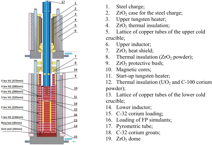
Because of the importance of the density variation and flip of layers the model should be validated. For validation the RCW test [18] performed in the frame MASCA Project. Prefomed in the cold crucible. Figure 2 demonstrates the facility schematics. The facility consists of two sections located vertically one above the other and integrated into one assembly. Corium briquettes and FP simulants are heated inductively in the lower section up to its melting temperature (2500 – 2600°С). After meting process was completed, steel sample is melted in the upper section, and molten steel relocated down through the discharge channel. The height of the melting compartment in the lower section was 700 mm; the inner diameter was 176 mm.
A pipe of the start-up tungsten heater 65 mm long located along the compartment axis was put into the loading down to the depth ~ 100 mm. Tungsten heater was heated by the inductor field with the frequency 8 – 10 kHz up to the temperature of 2500 – 2600 °С. In turn, the surrounding briquettes were heated from the tungsten tube by conduction and up to the formation of electrically closed rings and high enough temperature to reach sufficient value of electric conductivity in loaded corium (at f = 10 kHz, Tinitial heat generation≈ 2000 °С, close to sintering temperature).
After that, the corium intercepts the absorbed power of the electromagnetic field and corium is heated volumetrically to its melting temperature of about 2350 – 2450°С. At this moment, tungsten heater is retracted from the facility (tungsten is incompatible with the molten steel component). Propagation of the corium melting front from the centre to the periphery and then downwards through the loading with the increase of the high-frequency inductor power absorbed by the corium was controlled by the set of peripheral thermocouples.
A melting compartment of the upper section is formed by a tungsten pipe-heater insulated from the cold crucible pipes by the layers of Al2O3 coating (the layer is 10 mm thick) and of ZrO2 powder (the layer is 14 mm thick). Inside the
compartment, a stainless steel charge (a pipe ~ 9 mm thick) is placed into the case made from ZrO2 ceramics. At the
desired moment (after the production of the melt pool in the lower section), the tungsten heater is heated up to the temperature 2200 – 2400°С by switching on the upper inductor (the frequency of electric power supply is 2.4 kHz). Energy from the tungsten heater transferred by radiation, first to ZrO2 case and from that – to the stainless steel preform
that was melted and released down through the discharge channel made of ZrO2 ceramics.
1 2 3 4 6 7 water water 8 9 10 11 12 13 16 14 15 5 19 17 18
Gri Uo2 (20t mm) Br bot (40iq mm) 1 lev H1 (130mm) 2 lev H1 (220mm) 3 lev H1 (320mm) 4 lev H1 (380mm) 4 lev H2 (380mm) 5 lev H1 (470mm)
1. Steel charge;
2. ZrO2 case for the steel charge;
3. Upper tungsten heater; 4. ZrO2 thermal insulation;
5. Lattice of copper tubes of the upper cold crucible;
6. Upper inductor; 7. ZrO2 heat shield;
8. Thermal insulation (ZrO2 powder);
9. ZrO2 protective bush;
10. Magnetic cores; 11. Start-up tungsten heater;
12. Thermal insulation (UO2 and С-100 corium
powder);
13. Lattice of copper tubes of the lower cold crucible;
14. Lower inductor; 15. C-32 corium loading; 16. Loading of FP simulants; 17. Pyrometric tube; 18. C-32 corium groats; 19. ZrO2 dome
Figure 2. Scheme of the Facility and location of some thermocouples
In accordance with the test procedure simulation of the experiment has been conducted in three phases:
• Preliminary heating of corium by the tungsten cylinder;
• Heating of corium by high frequency generator;
• Steel addition and diffusion of uranium to steel.
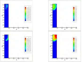
The first phase is characterized by the heating of tungsten cylinder and spreading of the heated area in radial direction. The duration of first phase was about 4300 s. At approximately 4000 s the heat generated in the facility was moved from the tungsten to corium and at 4300 s boundary skin layer was formed as it is shown in Figure 3. Temperature at the end of this phase reached the corium melting point.
The second phase is characterized by the gradual spreading of molten corium in axial direction. The duration of this phase was between 4300 and 8200 s. Heat is generated in a thin skin layer near cold crucible boundary. Power generated in the corium and isotherms for two time instants 5618 and 8173 s are shown in Figure 4. One can also see that near the heated end the spike of heat generation is observed. This spike which led to the increase in temperature was measured by thermocouples as it is shown in Figure 5. This behaviour is a good qualitative agreement with the measurements presented in the same Figure. The flow of molten corium during this phase is characterized by the complex flow formed from one side by the down flow near the cooled boundary and upward flow due to heating of skin layer as it is shown in Figure 4. Temperature during this phase is nearly uniform.
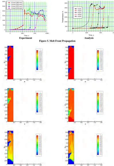
The third phase was between 8173 s and 9260 s up to the shut down of the test. In was assumed that before steel addition there was a stable crust at the top surface of corium. After steel addition it was assumed that crust was not broken, thus, just after steel delivery it formed a layer atop of corium. Screening of radiation from the upper surface led to the heating of corium region just below the steel corium interface. This in turn led to the softening of crust and loss its mechanical integrity allowing steel to interact with corium. Diffusivity of metal uranium in the steel led to the increase of metal density. When density of metal layer became larger than oxide density, the Rayleigh – Taylor instability was developed and caused movement of metal phase downward. This process is illustrated in Figure 6.
In spite of the fact that before the test there were significant uncertainties in the physical properties of the corium at low temperatures, the analysis indicated a good qualitative and even quantitative agreement between the test results and predictions.
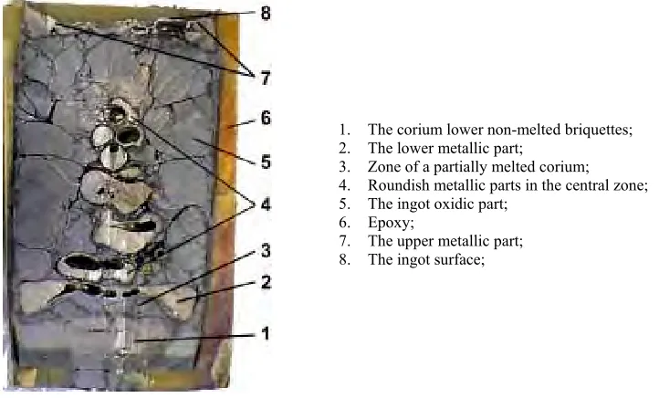
A view of the ingot after the test is shown in Figure 7. The following typical macrozones of the structure are observed:
• Non-melted briquettes (1) in the lower part. A well-definite boundary between the lower metallic part (2) the non-melted corium layer (1) was observed;
• the zone of the oxidic and metallic materials completely melted extends from the lower boundary of the lower metallic part up to the surface (8) and is about 260 mm thick. The zone (3) is hypothetically the corium partially molten within the temperature range between solidus and liquidus.
• the zone of the melted ingot oxidic part (5). The ingot contains three types of metallic parts:
• the lower metallic part (2) with a plate top and a dumbbell-like lower surface;
• the upper metallic part (7) is also of a dumbbell-like shape with bulges near the crucible walls;
• a cluster of roundish metallic parts (4) located along the ingot central axis.
As in was seen from the analysis qualitative picture can be explained by the diffusion of the metallic uranium into metal phase and development of Rayleigh –Taylor instability. This process is qualitatively captured by the code.
Figure 3. Power Generated in the Corium (left column) and Isotherms between 1000 and 2500 K for Two Time Instants – 4000 and 4300 Seconds
Figure 4. Power generated in the corium (left column) and isotherms between 2650 and 2950 K for Two Time Instants – 5618 and 8173 seconds
0 3600 7200 10800 0
500 1000 1500 2000 2500 3000
T
e
m
p
e
ra
tur
e,
oC
Time, s 4 level (380 mm) 3 level (320 mm) 2 level (220 mm) 1 level (130 mm)
0 3600 7200 10800
0 500 1000 1500 2000 2500 3000
mp31 mp32 mp33 mp34 mp35
T
em
per
at
u
re
, K
Time, s
Experiment Analysis Figure 5. Melt Front Propagation
Figure 6. Volumetric Part, Uranium Content and Temperature Distribution at 9232 s (left) and 9238 s (right)
1. The corium lower non-melted briquettes; 2. The lower metallic part;
3. Zone of a partially melted corium; 4. Roundish metallic parts in the central zone; 5. The ingot oxidic part;
6. Epoxy;
7. The upper metallic part; 8. The ingot surface;
Figure 7. Post test view of the ingot
Numerical modeling o SURC-4 test
Modeling of SURC-4 experiment was performed including both phases of the test – the heating up and melting of the metal cylinder phase and the phase of molten core concrete interaction. The focus of the simulation was in the validation of the chemical interaction model. In the test zirconium meltal was added at about 7200 seconds which interacted with steel. The oxidation chemical reactions were simulated which included the oxidation of zirconium and steel by steam released during interaction. An important reaction also included in the simulation was the reaction in the condenced phase between silica and free zirconium. This reactions led finally to the increase of the temperature as one can see in Figure 8. The calculated values of temperature are slightly lower, that is connected to the large losses in ceramics and in concrete in comparison with experiment.
In Figure 9 erosion in concrete, depending on time on different radiuses is shown. The upper set of points corresponds to experimental data in peripheral area, lower - corresponds to the case
r
=
0
. The computing results are presented in figure by a solid line. The process of interactions begins at time instant about 6000 second, that corresponds to experiment.0 1200 2400 3600 4800 6000 7200 8400 9600 10800 12000 0
200 400 600 800 1000 1200 1400 1600 1800 2000
Predictions Experiment
T(
K
)
Time (sec)
6000 7200 8400 9600
0 5 10 15 20
25 Predictions
r=0cm r=15cm r=18cm Experiment
r=0 r=R
cylinder
E
ros
io
n (
m
)
Time (s)
Figure 8.Comparison of the experimental and measured temperatures in steel
Figure 9. Erosion in concrete
CONCLUSIONS
The SOCRAT system of codes developed for realistic and the best estimate simulation of major severe accident phenomena in course of accident progression was supplemented with the model of corium behavior in the core catcher. This model being based on the CFD approach was developed to simulate the heat and mass transfer processes in the multicomponent mixtures, which includes 3D basic mathematical model for solving Navier-Stokes equations with variable properties and density jump under melting together with a energy equation. The key element of the proposed model is the simulation of the compositon of the melt and its properties which allows predict such phenomena as layer
flip. Model of such kind is applicable to the simulation of in vessel retention issues as layer configuration determine the heat loads of the reactor vessel, to the simulation of processes in the VVER-1000 core catcher and for simulation of molten core concrete interactions.
The developed model has been applied to the simulation of the RCW test conducted in the frames of MASCA Project and to the simulation of the SURC-4 MCCI test. As a result of numerical modeling of aforementioned experiments qualitative and quantitative agreement with experimental data was obtained including the diffusion of the components between phases and relocation of more dense phase due to Rayleigh – Taylor instability.
The model has been applied also to the the simulation of the phenomena in the core catcher designed for VVER-1000 reactor.
REFERENCES
1. Bolshov L.A., Strizhov V.F., “SOCRAT – the system of codes for realistic analysis of severe accidents”, Proceedings of the International congress for Advances in nuclear power, ICAPP ’06, Reno, NV USA, June 4-8, 2006, paper 6439.
2. V.Chudanov, A.Aksenova, A.Churbanov, V.Strizhov, “Current Status and Validation of CONV2D&3D”Proceedings of the OECD/CSNI Workshop on In-vessel Core debris Retention and Coolability, Garching, NEA/CSNI/R(98)18, 1999, pp. 223-234.
3. Aksenova, A.E., Chudanov, V.V., et al., “Complex of the programs for numerical modeling of experiments on interaction high-temperature melt of metals with zirconium dioxide concrete”, Preprint IBRAE RAS, 97-19, Moscow, 1997. (in Russian)
4. Copus, E.R. and Powers, D.A., “The SURC Test Series”, Second OECD - CSNI Specialist meeting on Molten Core Debris-Concrete Interactions, pp 51-66. Karlsruhe, Germany, April, 1992.
5. Thompson, D.H., Fink J.K., et al., “Thermal Hydraulic aspects of the large-scale integral MCCI test in the ACE Program” , Second OECD (NEA) CSNI Specialist Meeting on Molten Core Debris- Concrete Interactions, Karlsruhe, Germany, April, 1992.
6. Alsmeyer, H., Adelhelm, C., et al., “BETA-Experiments on Zirconium Oxidation and Aerosol Release During Melt-Concrete Interaction,” Second OECD - CSNI Specialist meeting on Molten Core Debris-Melt-Concrete Interactions, pp 67-82, Karlsruhe, Germany, 1-3 April, 1992.
7. Gardner, D.R., Bradley, D.R., “CORCON-Mod3: An Integrated Computer Model for Analysis of Molten Core-Concrete Interactions. Users manual”, NUREG/CR-5843, SAND92-0167, Sandia National Laboratories,
Albuquerque, NM, 87185, 1993.
8. Reinmann, M., Tiefel, S., “WECHSL-Mod2 Code: A Computer Program for the Interaction of a Core Melt with Concrete including the Long Term Behaviour”, KfK 4477, 1989.
9. V.G. Asmolov, S.V. Bechta, V.M. Berkovich, et al. “Crucible-type core catcher for VVER-1000 reactor”, Proceedings of the International congress for Advances in nuclear power, ICAPP ’05, Seoul, KOREA, May 15-19, 2005, Paper 5238.
10.Samigulin M.S., O.A.Voronova, G.G.Ivanova, et al. Problems of Nuclear Science and Techniques, No.2, pp. 24-33 (1997). In Russian.
11.Veshchunov M.S, A.Ye. Kiselev et. al. “SVECHA Code Package, Modeling of Core Degradation Phenomena at Severe Accidents”, Proceedings of 7-th International Topical Meeting on Nuclear Reactors Thermal Hydraulics (NURETH-7), Vol. 3, pp. 1914-1929 (1995).
12.Ignat'ev, A.V., Kiselev, A.E. Semenov, V.N., Filippov A.S. “HEFEST: Numeric modeling of the processes in the lower plenum of the VVER reactor during severe accident”. Preprint № 2003-13,IBRAE, 2003. In Russian
13.Melikhov O.I., Melikhov V.I., Sokolin A.V., Yakush S.E., Proceedings of 11-th International Topical Meeting on Nuclear Reactor Thermal-Hydraulics (NURETH-11) Popes Palace Conference Center, Avignon, France, Paper 067 (2005).
14.Aksenova A.E., Vabishchevic P.N., Pervichko V.A., et al. "Development and applications of the RASPLAV code". Bulletin of Russian Academy of Sciences, Series Energetic, No. 1, pp. 9-25 (1999). In Russian.
15.Tarasov V.I., BONUS 1.0. Inventories of radio nuclides in the reactors with thermal neutrons. Preprint 117-2001, IBRAE (2001). In Russian.
16. Veshchunov M.S. , Ozrin V.D. , V.E. Shestak, V.I. Tarasov, R. Dubourg, G. Nicaise, Proceedings of the 2004 International Meeting on LWR Fuel Performance, Orlando, Florida, Paper 1085 (2004).
17.Chudanov V.V., Aksenova A.E., Pervichko V.A. “Development of 3D unified computational tools to thermalhydraulic problems”. Proc. 10th International Topical Meeting on Nuclear Reactor Thermal Hydraulics (NURETH-10), October
5-11, 2003, Seoul, Korea. CD-disk paper № E00003
18. Chudanov V.V., Aksenova A.E., Pervichko V.A., Strizhov V.F. “The analysis of the large scale RCW test”, Proceedings of the MASCA Seminar 2004, Aix-En-Provence, pp. 217 - 240.