ABSTRACT
PARKHIDEH, BABAK. Control Methods and Architectures for Voltage-Sourced Converter Based Systems for Utility Applications. (Under the direction of Dr. Subhashish
Bhattacharya).
The voltage-Sourced Converter (VSC) is the preferred building block for Flexible AC Transmission Systems (FACTS) and utility-scale power electronics applications including HVDC transmission. Despite recent advances in the semiconductor technology, there are still many issues to address. This dissertation investigates the potentials and challenges that have been introduced for VSC-based transmission technologies. The technology is characterized in terms of switching frequency operation and switching patterns as either vector- or angle-controlled-based converters. Through the detail study of the VSC technology, this dissertation also offers unique applications of the VSC for utility applications which can be extended to high power mobile mining equipment.
This dissertation addresses the DC link voltage control issues for vector-controlled VSC-based transmission systems under power system disturbances. Having analyzed the state-of-the-art methods to mitigate the DC link voltage fluctuations under grid faults, a control structure in commonly used dq-synchronous frame is proposed. The proposed structure obviates the need for sequence extraction block or resonant notch compensator. Therefore, there is no diminishing bandwidth factor making it suitable for transmission applications for which the switching frequency is limited.
framework which uses the properties of Single Input Two Output (SITO) feedback system is developed for voltage-sourced converters. Clearly, one actuator, in this case angle cannot be used to regulate two outputs (active and reactive power) to arbitrary setpoint values. Nevertheless, this dissertation shows that a one-dimensional class of setpoint values is feasible for the VSC technology. This work is an enhancement in the operational region of existing shunt family of FACTS devices that can also be extended for transmission level VSC based HVDC systems.
transmission substations and transformers have a strong potential for the reliability, controllability and efficiency of the grid.
Control Methods and Architectures for Voltage-Sourced Converter Based Systems for Utility Applications
by
Babak Parkhideh
A dissertation submitted to the Graduate Faculty of North Carolina State University
in partial fulfillment of the requirements for the degree of
Doctor of Philosophy
Electrical Engineering
Raleigh, North Carolina 2012
APPROVED BY:
_______________________ _________________________ Dr. Subhashish Bhattacharya Dr. Mesut Baran
Committee Chair
_______________________ ________________________
Dr. Srdjan Lukić Dr. Aranya Chakrabortty
_______________________
DEDICATION
To My Parents
BIOGRAPHY
ACKNOWLEDGMENTS
First and foremost, I would like to express my sincere appreciation to my advisor, Dr. Subhashish Bhattacharya for his constant support and encouragement. Dr. Bhattacharya’s deep knowledge and great enthusiasm have been very inspirational to my research and development at North Carolina State University. Dr. Bhattacharya taught me how to conduct research independently and think out of the box. I hope to be privileged to benefit from his mentorship and collaboration throughout my future career.
I am grateful to my committee members, Professor Mesut Baran, Dr. Srdjan Lukic, Dr. Aranya Chakrabortty, and Dr. Xiangwu Zhang for their valuable suggestions and helps. I would also like to thank Professor Alex Huang, whom I had the opportunity to work with during my early years of graduate studies.
During my graduate studies, I had an opportunity to work with the New York Power Authority, US ABB Corporate Research Center, and Siemens Mining Industries. I would like to thank my mentors for their support, Dr. Bruce Fardanesh, Dr. Waqas Arshad, Dr. Hongrae Kim, Dr. Sandeep Bala, and Dr. Joy Mazumdar.
I appreciate the assistance from the staff members of the SPEC, FREEDM Systems Center and the ECE department, including Mr. Rogelio Sullivan, Ms. Karen Autry, Ms. Colleen Reid, Mr. Hulgize Kassa and Mrs. Elaine Hardin.
Outside work, many friends made my days in beautiful Raleigh. I would like to thank all of them specially Mr. Behzad Aghdashi, Mr. Koroush Sasan, Dr. Arash Sahbaee, Mr. Amirhosein Norouzi, Dr. Reza Yaesoubi, Dr. Mahmoud Moradi, Dr. Nariman Moezzi, Mr. Morteza Ashouri, Dr. Maryam Mazloumpour, Mrs. Azadeh Nakhostin, Dr. Hamed Mojarrad, Mr. Ali Marjani, Mr. Mohammad Etemadrezaei, Mr. Mohsen Dehghan, Mr. Ramin Safavizadeh, Dr. Salman Mohagheghi, Dr. Mahyar Zarghami, and Mr. Farbod Jahanbakhsh.
My deepest appreciation goes toward my parents and family, Dr. Vila Shokouhian, Dr. Shapour Parkhideh, Dr. Sayeh Parkhideh, Dr. Sahar Parkhideh, Dr. Roya Parkhideh, and Dr. Hamed Ghodsi who have always encouraged me to pursue my goals.
Last but not least, I would like to thank my all-time partner, friend, and love, for her endless support and love. Sometimes, we were thousands of miles away from each other, but she stood strong and helped me to be strong. Thank you my love, Nooshin Kiarashi!
TABLE OF CONTENTS
LIST OF FIGURES ... ix LIST OF TABLES ... xvii Introduction ... 1 Chapter 1.
Dissertation Scope ... 2 1.1
Dissertation Structure... 2 1.2
Vector-Controlled Voltage-Sourced Converter ... 5 Chapter 2.
Introduction ... 5 2.1
Background on Controlling the Voltage-Sourced Converter under Unbalanced 2.2
Conditions ... 7 Single VSC Control under Unbalanced Conditions... 7 2.2.1
BTB VSC Control under Unbalanced Conditions ... 11 2.2.2
Modeling of Voltage-Sourced Converter... 13 2.3
Model Validation ... 16 2.4
BTB VSC Closed-Loop Functions ... 16 2.4.1
System Configuration ... 20 2.4.2
Simulation Results to Verify the Modeling and Control Functions ... 21 2.4.3
VSC-Based BTB System Operation under Power Line Faults with Existing 2.5
Controllers... 25 Resilient Operation of Vector-Controlled VSC-Based BTB HVDC Systems ... 29 2.6
Method I: Integrator Factor Control (IFC)... 30 2.6.1
Method II: BackStepping Control (BSC) ... 33 2.6.2
Performance Comparison with the Proposed Control Structures ... 36 2.6.3
Generalized Controller for Back-to-Back Voltage-Sourced Converter under Power 2.7
System Disturbance ... 42 Modified Back-Stepping Control (BSC) for BTB VSC Systems ... 42 2.7.1
Dynamic Performance Evaluation of BTB VSC Systems with the Proposed 2.8
Generalized Control Architecture in RTDS ... 47 BTB VSC System for HVDC Applications ... 50 2.8.1
BTB VSC System for Drive (Wind) Applications ... 60 2.8.2
BTB VSC System for Transmission Transformer (Partial) Bypass ... 64 2.8.3
Angle-Controlled Voltage-Sourced Converter ... 69 Chapter 3.
Introduction ... 69 3.1
Feasibility Study ... 75 3.2
Single Input Two Output (SITO) Feedback Systems ... 79 3.3
Introduction ... 79 3.3.1
Preliminaries ... 80 3.3.2
Plant and Controller Directions ... 82 3.3.3
Plant/Controller Alignment ... 83 3.3.4
Plant Direction vs. Frequency ... 84 3.3.5
Perfect Plant/Controller Alignment ... 86 3.3.6
Disturbance Rejection ... 87 3.3.7
Feedback System Design for VSC as a SITO Closed-Loop System ... 89 3.4
Verification of the Proposed SITO Control Structure for VSC ... 97 3.5
Unified Power Flow Controller ... 97 3.5.1
Point-to-Point BTB HVDC Applications ... 101 3.5.2
Discussion of Component Design in Angle-Controlled Converters ... 103 3.5.3
Summary ... 108 3.6
Modular Transformer Converter ... 110 Chapter 4.
Background ... 110 4.1
Transformer Outages ... 115 4.1.1
Effect of New Intermittent Distributed Generation on Existing Assets ... 121 4.1.2
Towards Smart Transmission Substations ... 124 4.2
Controllable Transformers ... 125 4.2.1
Recovery Power Transformer ... 126 4.2.2
Phase Shifting Transformer (PST) ... 127 4.2.3
Unified Power Flow Controller (UPFC) ... 130 4.2.4
Power Flow Control at Transmission Substations ... 131 4.2.5
Substation Power Flow Controller Connecting Configurations ... 136 4.3
Shunt-Shunt Connecting Configuration - Substation Voltage/Phase Angle 4.3.1
Controller ... 136 Series-Shunt Connecting Configuration – Substation Power Flow Controller .... 144 4.3.2
Series-Series Connecting Configuration – Dual Series Static Compensator ... 149 4.3.3
Comparison of the Proposed CSTC- and Conventional FACTS-Based Power Flow 4.3.4
Dynamic Performance of MTC-Based CSTC ... 165 4.5
Shunt-Shunt Connecting Configuration – Substation Voltage/Phase Angle 4.5.1
Regulator ... 165 Series-Shunt Connecting Configuration – Substation Power Flow Controller .... 169 4.5.2
Series-Series Connecting Configuration – Substation Power Flow Controller .... 170 4.5.3
Summary ... 186 4.6
Supplementary Energy Storage and Advanced architectures for Grid-Chapter 5.
Connected High Power AC Multi-Motor Applications ... 189 Introduction ... 189 5.1
All-AC Drive System for High power Mobile Mining Applications ... 190 5.2
Front-End Converters for Mobile Mining Equipment ... 192 5.3
The Current State-of-the-Art Active Front End Performance for Mobile Mining 5.4
Equipment ... 194 Supplementary Energy Storage System for Mobile Mining Equipment ... 200 5.5
Energy Storage Technology Selection ... 200 5.5.1
Energy Storage System Factors ... 203 5.5.2
Annuity Method to Select Energy Storage Technology ... 205 5.5.3
Energy Storage Properties and Assumptions ... 207 5.5.4
Energy Storage Comparison for High Power Mining Equipment ... 210 5.5.5
Ultracapacitor Integration into Existing Mobile Mining Converters ... 215 5.6
Hybrid Front End Configurations for High Power Multi-Motor Applications... 219 5.7
Unidirectional Front End Converters ... 219 5.7.1
Hybrid Front End Converters... 223 5.7.2
Summary ... 227 5.8
Conclusions and Future Work ... 229 Chapter 6.
Conclusion of Present Work ... 229 6.1
Contributions... 233 6.2
Future Work ... 235 6.3
LIST OF FIGURES
Figure 1-1. Example of VSC-based transmission. ... 1 Figure 1-2. Example of CSC-based transmission. ... 2 Figure 2-1. Simplified schematic of existing closed loop BTB VSC systems. ... 5 Figure 2-2. Bus voltage variations under normal and single-line-to ground fault in three phase
abc-stationary and two phase dq-synchronous reference frames. ... 8 Figure 2-3. An Example of current state-of-the-art VSC controller under unbalanced
conditions, 18. ... 10 Figure 2-4. Schematic of a voltage-sourced converter. ... 13 Figure 2-5. Conventional (Existing) BTB VSC-based HVDC system controller
implementation. ... 17 Figure 2-6. Proposed BTB VSC-based HVDC system controller implementation. ... 17 Figure 2-7. BTB VSC system standby operation performance with a change in the reference
DC link voltage from 250V to 220V. ... 22 Figure 2-8. BtB VSC system performance with a change in the reference reactive power
command from -12 KVAr to +12 KVAr for the rectifier side and from +12 KVAr to -12 KVAr for the inverter side. ... 24 Figure 2-9. BtB HVDC system performance with a change in the reference active power
command from zero to 10.8 KW while the rectifier and inverter sides provide -8.1 KVAr and +8.1 KVAr reactive power respectively... 25 Figure 2-10. Performance of the conventional VSC-based BTB system when a SLG fault
occurs in the rectifier side. ... 27 Figure 2-11. Performance of the conventional VSC-based BTB system when a SLG fault
occurs in the inverter side. ... 28 Figure 2-12. Proposed Integral Factor Control (IFC) structure for the DC link controller in
VSC-based HVDC applications. ... 32 Figure 2-13. Proposed Back-Stepping Control (BSC) structure for the DC link controller in
VSC-based HVDC applications. ... 35 Figure 2-14. DC link voltage performance comparison with the proposed controllers under a
single line to ground fault. ... 37 Figure 2-15. Effect of the proposed controllers on the d-component of the current under a
single line to ground fault. ... 38 Figure 2-16. DC link voltage performance comparison with the proposed controllers under
phase reversal. ... 39 Figure 2-17. Effect of the proposed controllers on the d-component of the current under
phase reversal. ... 40 Figure 2-18. Phase compensation effect of the proposed controllers under phase reversal. .. 41 Figure 2-19. Proposed backstepping control structure for the DC link voltage controller
converter in a BTB VSC system. ... 46 Figure 2-20. Implemented proposed control structure in the synchronous frame to generate
Figure 2-22. BTB VSC system for HVDC applications ... 51 Figure 2-23 Start-up dynamic performance of the BTB VSC system as in HVDC applications
and unity power factor operation of 1 PU power under balanced conditions-RTDS results. ... 52 Figure 2-24. Dynamic performance of the BTB VSC system as in HVDC applications,
changing power flow direction, with no change in reactive power reference under balanced conditions- RTDS results. ... 53 Figure 2-25. Performance comparison of the BTB VSC system with the proposed controller
and commonly used control schemes for HVDC applications under an unbalanced condition of 50% single-line voltage sag in the power flow controller side (average model). ... 54 Figure 2-26. Dynamic performance of the BTB VSC system as in HVDC applications under
an unbalanced condition of 50% single-line voltage sag in the power flow controller side- RTDS results. ... 55 Figure 2-27. Performance comparison of the BTB VSC system with the proposed controller
and commonly used control schemes for HVDC applications under an unbalanced condition of 50% single-line voltage sag in the DC link voltage controller side (average model). ... 56 Figure 2-28. Dynamic performance of the BTB VSC system as in HVDC applications under
an unbalanced condition of 50% single-line voltage sag in the DC link voltage controller side- RTDS results. ... 56 Figure 2-29. Performance comparison of the BTB VSC system with the proposed controller
and commonly used control schemes for HVDC applications under an unbalanced condition of 50% single-line voltage sag in the DC link voltage controller side operated as an inverter (average model). ... 58 Figure 2-30. Dynamic performance of the BTB VSC system in HVDC applications under an
unbalanced condition of 50% single-line voltage sag in the DC link voltage controller side operated as an inverter- RTDS results. ... 58 Figure 2-31. Performance comparison of the BTB VSC system with the proposed controller
and commonly used control schemes for HVDC applications under an unbalanced condition of 50% in phase B and 90% in phase C voltage sag in the power flow
controller side operated as the rectifier (average model). ... 59 Figure 2-32. Dynamic performance of the BTB VSC system in HVDC applications under
unbalanced condition of 50% in phase B and 90% in phase C voltage sag in the power flow controller side operated as the rectifier- RTDS results... 59 Figure 2-33. Simplified BTB VSC system in drive (wind) applications. ... 61 Figure 2-34. Performance comparison of the BTB VSC system with the proposed controller
and commonly used control schemes under an unbalanced condition of 50% single line voltage sag in the DC link voltage controller for the drive application operated at 30 Hz (average model). ... 61 Figure 2-35. Dynamic performance of the BTB VSC system in drive (wind) applications
Figure 2-36. Performance comparison of the BTB VSC system with the proposed controller and commonly used control schemes under an unbalanced condition of 50% in phase B and 30% in phase C voltage sag in the DC link voltage controller for a drive application
operated at 30 Hz (average model). ... 63
Figure 2-37. Dynamic performance of the BTB VSC system in drive (wind) applications under an unbalanced condition of 50% in phase B and 30% in phase C voltage sag in the DC link voltage controller side (grid) and drive side operating at 30 Hz- RTDS results. ... 63
Figure 2-38. BTB VSC system in hybrid power system as transmission transformer (partial) back-up for life extension of the transmission transformer or contingencies. ... 64
Figure 2-39. Performance comparison of the BTB VSC system with the proposed controller and commonly used control schemes under unbalanced condition of 90% voltage sage in phase A for hybrid power system applications (average model). ... 65
Figure 2-40. Dynamic performance of the BTB VSC system as in hybrid systems for transmission transformer (partial) back-up under unbalanced condition of 90% voltage sag in phase A- RTDS results. ... 66
Figure 3-1. General schematic of voltage-sourced converter. ... 70
Figure 3-2. A 24 pulse angle-controlled VSC. ... 71
Figure 3-3. Operating characteristics of angle-controlled VSC as STATCOM. ... 71
Figure 3-4. Output voltage vector construction in pulse-VSCs. ... 73
Figure 3-5. Reactive power transfer capability of the power system with constant active power... 75
Figure 3-6. DC link voltage steady state operating points vs. output voltage angle... 78
Figure 3-7. d-component of the current(representing the active power) steady state operating points vs. output voltage angle... 78
Figure 3-8. q-component of the current (representing the reactive power) steady state operating points vs. output voltage angle. ... 79
Figure 3-9. General Single Input Two Output (SITO) automatic feedback system. ... 80
Figure 3-10. Low bound on (0) o I T T ... 91
Figure 3-11. Plant (converter system) direction vs. frequency. ... 91
Figure 3-12. Alignment angles variations vs frequency. ... 93
Figure 3-13. Gain/phase plot of the input complementary sensitivity function. ... 94
Figure 3-14. Converter performance when it is controlled with just the output voltage angle. ... 95
Figure 3-15. Transient response of the angle-controlled VSC for a change in active power in rectifier mode. ... 96
Figure 3-16. Transient response of the angle-controlled VSC for a change in active power in inverter mode. ... 96
Figure 3-17. Transient response of the angle-controlled VSC for a change in reactive power. ... 97
Figure 3-18. Hybrid-controlled BTB VSC for power flow control. ... 98
Figure 3-20. Substation transformer power flow dynamics with hybrid-controlled BTB VSC.
... 99
Figure 3-21. Operational performance (voltages) of the BTB VSC system as the power flow controller. ... 100
Figure 3-22. Angle-controlled BTB VSCs for HVDC applications. ... 102
Figure 3-23. Active power dynamic performance of the angle-controlled BTB VSC system. ... 102
Figure 3-24. Reactive power dynamic performance of the angle-controlled BTB VSC system. ... 103
Figure 3-25. DC link voltage dynamic performance of the angle-controlled BTB VSC system. ... 103
Figure 3-26. Theoretical load rejection capability of an angle-controlled VSC vs. interfacing inductance value for an active power reference of 1.5PU. ... 106
Figure 3-27. Dynamic performance analysis of the angle-controlled BTB VSC system to show the converter system disturbance rejection capability with interfacing inductance of 15% PU. ... 107
Figure 3-28. Dynamic performance analysis of the angle-controlled BTB VSC system to show the converter system disturbance rejection capability with an interfacing inductance of 50% PU. ... 108
Figure 4-1. Power interruption effects on power loss and number of affected customers. .. 111
Figure 4-2. Cost of power interruptions for U.S. customers in 2002... 112
Figure 4-3. Wind and solar generation availability for selected countries. ... 114
Figure 4-4. US Midwest region wind generation capacity profile. ... 114
Figure 4-5. Installation of power transformers base GVA per year additions in US... 116
Figure 4-6. Transformer “Element-Initiated Only” sustained automatic outage data based on different transmission voltage levels. ... 118
Figure 4-7. Transformer other than “Element-Initiated Only” sustained automatic outage data based on different transmission voltage levels. ... 118
Figure 4-8. Transformer sustained automatic outage attributes-Outage Mode code. ... 119
Figure 4-9. Transformer sustained automatic outage attributes-Event Type. ... 120
Figure 4-10. US Transmission transformer (>200 kV) availability in 2010. ... 121
Figure 4-11. New generation effects on existing assets - wind generation, State level. ... 123
Figure 4-12. Alternative solution to reroute the power flow for new wind generator output (expensive solution, yet ineffective). ... 124
Figure 4-13. Recent advances in active transformers (simplified schematics) - not commercialized yet. ... 125
Figure 4-14. An example of an ABB polytransformer installation in Spain, 2005, 64. ... 127
Figure 4-15. Simplified circuit diagram of phase shifting transformer, 82. ... 129
Figure 4-16. Two phase-shifting transformers, 525kV, 650 MVA throughput power, angle variations =+/-24º, Siemens. ... 129
Figure 4-17. 2x100 MVA NYPA CSC at Marcy on 345kV Transmission lines. ... 131
Figure 4-19. Schematic of introduced power flow controller at substation. ... 134 Figure 4-20. Possible connecting configurations of the proposed power flow controller. ... 135 Figure 4-21. Flexible transmission controller frame with Modular Transformer Converter
(MTC). ... 135 Figure 4-22. Representative schematic of MTC-based Convertible Static Transmission
Controller (CSTC). ... 136 Figure 4-23. Two hardware-based asset management approaches for life time extension of a
transformer under forced reduced operation and distorted power throughput. ... 138 Figure 4-24. Distributed CSTC application in normal forced reduced operation of
transformers and distributed and aggregated CSTCs under contingencies on IEEE 30 bus mesh AC system. ... 138 Figure 4-25. Test system to analyze the CSTC in a shunt-shunt connecting configuration. 140 Figure 4-26. Vector analysis of the CSTC for shunt-shunt configuration operated as
voltage/phase-angle regulator for transformer back-up as shown in Figure 4-25. ... 140 Figure 4-27. Shunt-shunt connecting configuration for supporting only reactive power
injection to increase the transmittable power. ... 141 Figure 4-28. Range of active power through the transformer relative to the initial power,
shunt-shunt configuration. ... 143 Figure 4-29. Relative PQ effective operating region of a shunt-shunt controller. ... 143 Figure 4-30. Vector analysis of the transformer power flow controller for a series-shunt
configuration. ... 145 Figure 4-31. Example of a series-shunt option vector analysis for zero reactive power
transfer. ... 146 Figure 4-32. MTC based CSTC test system values in series-shunt mode of operation in IEEE 30 bus. ... 146 Figure 4-33. Power flow model for the series-shunt connecting configurations. ... 147 Figure 4-34. MTC-based CSTC as the substation power controller in the IEEE 30-bus
system. ... 147 Figure 4-35. Range of active power through the transformer relative to the initial power,
series-shunt configuration. ... 148 Figure 4-36. Relative PQ effective operating region of the series-shunt controller. ... 148 Figure 4-37. Single phase equivalent circuit of MTC in series-series mode. ... 149 Figure 4-38. Vector analysis of transformer power flow controller for series-series
configuration. ... 150 Figure 4-39. Test system to compare different modes of the CSTC and common FACTS. 152 Figure 4-40. P-Q operating characteristics with DSSC, UPFC, IPFC, and SSSC (Natural
Power Flow: P0=0.9174 (pu), Q0=0.0401(pu)). ... 153
Figure 4-41. P-Q operating characteristics with DSSC, UPFC, IPFC, and SSSC (Natural Power Flow: P0=0.9248 (pu), Q0=1.0351(pu)). ... 153
Figure 4-42. P-Q operating characteristics with DSSC, UPFC, IPFC, and SSSC (Natural Power Flow: P0=0.9195 (pu), Q0=-1.0099(pu)). ... 154
Figure 4-44. An example of MTC based on three-level NPC MV drive converters- Medium
Risk. ... 158
Figure 4-45. Single phase approaches for some transformerless integrations, more applicable for large transformers- High Risk. ... 159
Figure 4-46. Efficiency comparison of an MTC shown in Figure 4-44 with different semiconductor devices and controls (no passive filters). ... 161
Figure 4-47. Advanced angle-control structure for a VSC. ... 161
Figure 4-48, A 24-pulse angle-controlled VSC. ... 162
Figure 4-49. Generalized vector-control structure for VSC ... 162
Figure 4-50. Representative Modular Transformer Converter (MTC)-based systems (red lines indicate parallel integration and blue ones show series integration). ... 163
Figure 4-51. Representative voltage construction and scale-up in two series MTCs. ... 164
Figure 4-52. Control structure of the CSTC in the shunt-shunt mode of operation with an approximately constant substation power line. ... 167
Figure 4-53. Proposed control structure of the CSTC in the shunt-shunt mode of operation as a substation voltage/phase angle regulator. ... 168
Figure 4-54. PSCAD simulation results in per unit for the shunt-shunt mode of operation for transformer partial bypass or power flow control without changing the power system power flow shown in Figure 4-39. ... 169
Figure 4-55. PSCAD simulation results in per unit for the CSTC series-shunt mode of operation in the test system shown in Figure 4-39. ... 170
Figure 4-56.Active and reactive power Bode plot representation of the DSSC with operating points of P=1.0024, Q=0.02, and Id0=1.0026 PU (High current, high active power, and low reactive power case). ... 175
Figure 4-57. DC link voltage (Vdc2) Bode plot representation of the DSSC with operating points of P=1.0024, Q=0.02, and Id0=1.0026 PU (High current, high active power, and low reactive power case). ... 176
Figure 4-58.Active and reactive power Bode plot representation of the DSSC with operating points of P=-0.0912, Q=-0.1986, Id0=0.2186 PU (Low current, low active power, and low reactive power case). ... 177
Figure 4-59. DC link voltage ( 2 dc V ) Bode plot representation of the DSSC with operating points of P=-0.0912, Q=-0.1986, Id0=0.2186 PU (Low current, low active power, and low reactive power case). ... 178
Figure 4-60.Active and reactive power Bode plot representation of the DSSC with operating points of P=1.0925, Q=1.8177, Id0=2.1208 PU (High current, high active power, and high reactive power case). ... 179
Figure 4-61. DC link voltage ( 2 dc V ) Bode plot representation of the DSSC with operating points of P=1.0925, Q=1.8177, Id0=2.1208 PU (High current, high active power, and high reactive power case). ... 180
Figure 4-62. Power flow controller inverter control structure of DSSC. ... 181
Figure 4-64. Dynamics of active power flow control in a DSSC under low reactive power
loading... 183
Figure 4-65. Dynamics of reactive power change in a DSSC under low reactive power loading... 184
Figure 4-66. Dynamics of active power control in DSSC under high reactive power loading. ... 185
Figure 4-67. Dynamics of reactive power control in a DSSC under high reactive power loading... 186
Figure 5-1. 24MW AC-drive dragline in an open-pit mine, 89. ... 190
Figure 5-2. An example of a 24MW AC-drive dragline deck plan, 87. ... 191
Figure 5-3. State-of-the-art high power AC drive system. ... 193
Figure 5-4. Example of a typical mining load profile. ... 193
Figure 5-5. Simplified synchronous frame-based controller implementation for staggered Active Front Ends (AFE). ... 196
Figure 5-6. Simulated 1.5MW shovel currents with two staggered AFEs. ... 197
Figure 5-7. Simulated 3MW shovel currents with four staggered AFEs. ... 198
Figure 5-8. Simulated PCC currents in the 24MW dragline with 32 staggered (11.25° degree) AFEs and 8 split DC link voltages. ... 200
Figure 5-9. Capital cost comparison of selected energy storage technologies, 94. ... 201
Figure 5-10. Energy density comparison of selected energy storage technologies, 94. ... 202
Figure 5-11. Efficiency comparison of selected energy storage technologies, 94. ... 202
Figure 5-12. The factor influencing battery technology comparison. ... 204
Figure 5-13. An example of a cash flow diagram. ... 206
Figure 5-14. Cash flow model with multiple replacements. ... 206
Figure 5-15. Comparison of commercially available energy storage technology for a dragline. ... 211
Figure 5-16. Comparison of energy prices for selected energy storage technologies for a dragline. ... 211
Figure 5-17. Comparison of energy prices of selected energy storage technologies for shovels... 213
Figure 5-18. Comparison of selected energy storage technologies for shovel. ... 214
Figure 5-19. Replacement of selected energy storage technologies for shovel. ... 215
Figure 5-20. Simulated dynamic performance of the 1.5MW shovel integrated with an ultracapacitor directly at the DC link. ... 217
Figure 5-21. Schematic of a multi-motor AC drive system integrated with an ultracapacitor with a separate DC/DC converter. ... 217
Figure 5-22. Example of an ultracapacitor module and a DC/DC converter suitable for mining applications. ... 218
Figure 5-23. Proposed control structure of the shovel converter system when the integrated DC/DC converter as shown in Figure 5-21 contributes to the drive DC link voltage control. ... 218
Figure 5-25. Unidirectional front end assisted with fractionally rated hybrid active filter integrated with ultracapacitor. ... 221 Figure 5-26. Simulated 1.5MW unidirectional front end assisted with hybrid active filter as
shown in Figure 5-25. ... 222 Figure 5-27. Results of active filter controller hardware verification for a six-pulse diode
bridge front-end. ... 222 Figure 5-28. Hybrid configuration for large multi-motor applications. ... 223 Figure 5-29. Proposed control structure of hybrid front end architecture for large
multi-machine systems including mining equipment. ... 224 Figure 5-30. Hybrid front end’s PCC current as shown in Figure 5-28. ... 225 Figure 5-31. Frequency spectrum of load and PCC currents for the proposed hybrid
configuration. ... 226 Figure 5-32. DC link dynamics of hybrid configuration- an example. ... 226 Figure 5-33. Nominal PCC current (ph A) of the hybrid configuration with a two-thyristor
LIST OF TABLES
Table I. Prototype BTB VSC System Parameters to Verify the Modeling ... 20
Table II. VSC BTB System Parameters with the Generalized Control Structure ... 50
TABLE III. Angle-Controlled System Parameters in P.U. ... 76
Table IV. High Power Mobile Mining System Parameters ... 196
Table V. Project Requirements for Integrating Energy Storage Systems ... 208
Table VI. Energy Storage Technology Properties-I ... 209
Table VII. Energy Storage Technology Properties-II ... 209
INTRODUCTION
Chapter 1.
The Voltage-Sourced Converter (VSC) is the preferred building block for Flexible AC Transmission Systems (FACTS) and utility-scale power electronics applications including High Voltage DC (HVDC) Transmission, Figure 1-1. Despite of advances in semiconductor technology, there are still many issues to address, including efficiency, reliability, availability, quality, and effectiveness of the utility power electronics. This PhD dissertation is organized to address these issues focusing on utility applications of power electronics using VSC technology. Currently, the most prominent application and outlook for VSC technology is (multi-terminal) HVDC transmission where traditionally Current-Sourced Converter (CSC) technology with line-commutated semiconductor devices is deployed, Figure 1-2.
Figure 1-1. Example of VSC-based transmission.
Rs Ls Rs
Ls 3 phase
Network
#1 Vdc
3 phase Network
Figure 1-2. Example of CSC-based transmission.
Dissertation Scope
1.1
This dissertation is divided into two main parts. The first part deals with the problem of efficiency, reliability, availability, and quality of the converter (VSC) operation when they are installed in the grid. The proposed solutions are based on comprehensive modeling and analyzing the results which will be covered in Chapter 2 and Chapter 3. The second part, Chapter 4 and Chapter 5 of this dissertation offers some unique applications and architectures for which VSC is deployed. With the help of the knowledge gained in the first part, the proposed system benefits from high efficiency, high availability, and potentially low cost.
Dissertation Structure
1.2
Chapter 2- examines the vector-controlled or PWM-(Pulse Width Modulation) based VSC for transmission applications and presents detailed modeling of this type of converter.
Rs Ls Rs
Ls 3 phase
Network
#1 Vdc
3 phase Network
In particular, resilient operation of the converters under power system disturbances is proposed, considering the rating and low switching frequency operation of the converters.
Chapter 3 introduces the active power transfer capability of VSC through the angle control structure. This chapter provides a design framework that enables the high power high voltage VSC to operate at line frequency with a superior harmonic spectrum.
Chapter 4 introduces the Modular Transformer Converter (MTC) which is the building block for a versatile and transportable transmission controller. Several MTCs can be arranged to form a Convertible Static Transmission Controller (CSTC). The proposed transmission controller can perform several functions including power flow control for renewable resources transmission and transformer back-up for disaster management or life extension purposes. This structure has several advantages in comparison with conventional FACTS controllers, one of which is modularity for manufacturers and utilities using standard high power electronic systems. In addition, different connecting configuration options with different functions can be obtained in the transmission controller with MTC structures. These features allow them to be deployed dispersed or aggregated to meet power, voltage, VAR and configuration requirements.
terms of the required number of replacement units over the life time of the mining equipment. Consequently, this dissertation proposes that the enabling technology for energy storage integration for mobile mining equipment will be front end converters with higher power density than the current state-of-the-art technologies.
Chapter 6 presents the conclusions of the present work and offers future work and research paths that can be taken from the opportunities that this dissertation has identified.
VECTOR-CONTROLLED
VOLTAGE-Chapter 2.
SOURCED CONVERTER
Introduction
2.1
Equation Chapter (Next) Section 1
It is desirable to have high power high-voltage electronics based systems available during power system faults when they may be needed the most. If the protection measures trip the converter system it can take several fractions of an hour, depending on the size of the converter, to discharge the DC link and check the healthiness of the whole system. Hence, several practical methods have been proposed and implemented to keep a system running under power system faults and disturbances, 1-2.
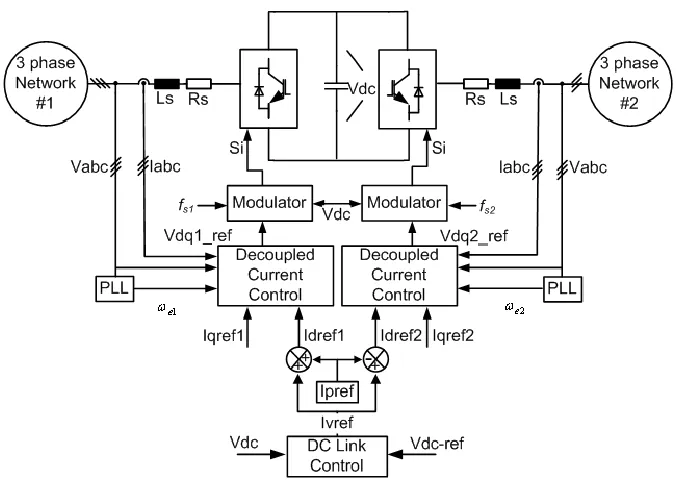
transformers, 10 the dynamic operation of the VSC under power system disturbances must be revisited. This dissertation proposes an alternative control framework to obtain robust DC link voltage with specific attention to designing the DC link controller VSC in a Back-To-Back (BTB) configuration which is different from existing control structures as shown in Figure 2-1. The proposed controller is implemented in the commonly used dq-synchronous frame without sequence extraction.
Background on Controlling the Voltage-Sourced Converter under
2.2
Unbalanced Conditions
Single VSC Control under Unbalanced Conditions
2.2.1
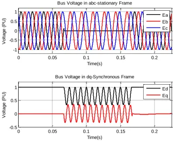
Figure 2-2. Bus voltage variations under normal and single-line-to ground fault in three phase abc-stationary and two phase dq-synchronous reference frames.
Rioual et al. in 14 probably proposed the very first control scheme for the VSC that regulates the instantaneous power generated under network voltage dips. Their work of 14 is mainly generated current references in both positive and negative synchronous references to regulate the power at the PCC. Since then researchers have been developing “enhanced” control schemes mostly to minimize input harmonics which is coupled to DC link voltage ripples. For instance, Stankovic et al, 15 presented a model that can eliminate the harmonics for generalized unbalanced conditions. However, this method needs a great deal of computations steps for DSP-based control. In 16 and 17, authors consider the instantaneous
0 0.05 0.1 0.15 0.2
-1 -0.5 0 0.5 1
Time(s)
V
o
lt
a
g
e
(
P
U
)
Bus Voltage in abc-stationary Frame
Ea Eb Ec
0 0.05 0.1 0.15 0.2
-0.5 0 0.5 1
Time(s)
V
o
lt
a
g
e
(
P
U
)
Bus Voltage in dq-Synchronous Frame
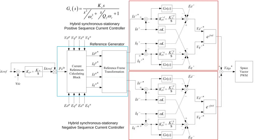
as of today is reported in 23 which has implemented the whole control frame in the stationary frame resulting in a new current reference generator. Fast dynamic performance with small DC link voltage ripple in a 20 kVA/10 kHz PWM prototype converter under 30% supply voltage dip is reported. A nice feature of the scheme is that no PLL strategies are needed but constant line frequency is assumed and sinusoidal compensators as 18 are deployed due to the control logic of the oscillating references.
Figure 2-3. An Example of current state-of-the-art VSC controller under unbalanced conditions, 18.
Hybrid synchronous-stationary Positive Sequence Current Controller
Hybrid synchronous-stationary Negative Sequence Current Controller
Reference Generator
2
2 1
r r
f r r
K s
G s
s s
Q
BTB VSC Control under Unbalanced Conditions
2.2.2
voltage oscillations by using the notch filter approach; therefore, the same issues exist as for a single VSC. For a specific voltage-sourced converter BTB HVDC system, Hagiwara et al., 30 proposes a unique DC link control structure that has the load feedforward term. With the proposed structure a robust DC link voltage is achieved if the fault occurs in the inverter side. It has been shown that load estimation can improve the converter performance. In fact, 31 had shown that adding the load estimation into the main controller better attunes the DC link voltage to load power change attuned more. Parkhideh et al. 32 also showed how it is possible to remove the varying load effect from a closed loop large mining converter control system (1.5-24 MW) which is basically a BTB VSC system.
On the other hand, there are emerging interests to have medium voltage interfaces for renewable integration such as wind generation, currently up to 10 MVA with direct drive technologies (BTB VSC), 9. Authors of 33 have presented a unique controller in the stationary frame for direct drive wind generation systems that is based on reactive power compensation. Applying the proposed method insures balanced grid currents even under power system faults. Nonetheless, due to possible low speed operation of wind turbines, DC link dynamics have been addressed as one of the key factors which affect the operation of the turbine, 34. Therefore, more investigations are essential to determine the proper control strategy; balanced currents or a stiff DC link voltage.
hand, there is no direct control input that can remove this interaction or disturbance with conventional frequency oriented controller design. This work introduces a commonly used dq-synchronous-based framework to design a more robust controller for relatively low switching frequency (9~15 times) PWM or vector-controlled BTB VSC systems.
Modeling of Voltage-Sourced Converter
2.3
The modeling of voltage-sourced converter, the building block of the BTB system is coming mainly from Middlebrook’s work stated in many literatures such as 35. This modeling is based on the principal circuit analysis writing voltage and current equations for storage elements known as state equations. The general schematic of a three phase voltage-sourced converter circuit is shown in Figure 2-4 and the state equations of a VSC in the three phase stationary coordinates are as follows:
abc s abc abc
abc
s s s
dI R E V
I
dt L L L (2.1)
DC DC DC load
DC p DC DC DC
dV I V P
dt C R C C V (2.2)
Figure 2-4. Schematic of a voltage-sourced converter.
Ea Eb Ec
Ls Rs
Ls Rs
Ls Rs
Cdc Rp Vdc
PLoad
Va
Vb
Vc
Active Load
In order to benefit all decoupling and constant properties of a two phase system instead of a three phase one, dq- transformation is considered to convert all quantities in the abc- stationary coordinate frame to the synchronous reference frame.
d s d d
d q
s s s
dI R E V
I I
dt L L L (2.3)
q s q q
q d
s s s
dI R E V
I I
dt L L L (2.4)
In (2.3) and (2.4), Vd and Vq are the converter output voltages in the synchronous frame.
The modulation index can be also written in this frame as (2.5), where k depends on the modulation technique. In this work, we use the vector control method denoted by Schauder et al. in 7.
q d
d q
DC DC
V V
m m
kV kV
(2.5)
In many literature sources, especially for DC/DC converters, the modulation index is used as the control input; therefore, (2.3) and (2.4) present the non-linear system. DC link dynamics are also non-linear by introducing the definition for IDC as (2.6). However, by
considering Vd and Vq as the control inputs, those equations, (2.3) and (2.4), can be treated as
linear ones. Also, power balance is used to derive the equation for the DC link voltage, neglecting the interface losses as in (2.7). Ea (the PCC phase-A voltage) is aligned with the
long as Ed and Eq are constant. Consequently, no linearization around specific operating
points is needed and the small-signal VSC model looks similar to the large-signal model. The state-space representation of the VSC can be obtained from (2.3), (2.4), and (2.7). From what has been mentioned, the matrix form of the state space equations can be represented as (2.8) and (2.9), where x(t) is the state variable vector, u(t) is the input vector and e(t) is considered as the disturbance vector, (2.10)1.
2 =3
DC d d q q
I m I m I (2.6)
2 3 2
3 q q 2 2
DC d d DC load
DC DC p DC DC
E I
dV E I V P
dt C C R C C (2.7)
( ) ( ) ( ) ( )
x t Ax t Bu t Ke t (2.8)
( ) ( ) 0 ( )
y t Cx t u t (2.9)
2
x( ) , u( ) , e( )
d d
d
q q
q
load DC
I E
V
t I t t E
V
P V
(2.10)
Although there is a possibility of using the so-called Instantaneous PLL (IPLL) presented in 38 to discard the effect of the q-component of the voltage vector even under unbalanced conditions (at least in the model ), this work considers common PLL structures in order to unify the problem.
1
Model Validation
2.4
BTB VSC Closed-Loop Functions
2.4.1
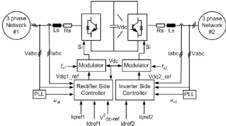
Currently, in most of the literature the BTB VSC system is designed and seen as a single device, hence the two sides support the DC link. The detailed VSC-based BTB HVDC converter system is depicted in Figure 2-5. While the private power system model suggests that the consumer parties should bid and pay for only the portion they acquire, the available correct models usually ignore this practical fact. It should be noted that DC link variations are mainly due to converter losses and transient operation of the system. Therefore, in this work, the one-sided DC link voltage controller shown in Figure 2-6 is proposed. The summary of controller function is divided in two parts:
The rectifier side which should supply or provide active power while it can support its side reactive power.
Figure 2-5. Conventional (Existing) BTB VSC-based HVDC system controller implementation.
To design a closed loop system, the eigenstructure assignment or any linear feedback design method can be used to place the poles at the desired locations. Eigenstructure assignment is explained for STATCOM in 39 and this method is extended to BTB VSC systems to develop the general controller.
The control input can be determined based on the matrix network of (2.11). F is the state feedback matrix, which should be designed based on the response time according to the eigenstructure. Matrix T for external input access and Matrix M for disturbance rejection purposes are assumed.
( ) ( ) ref( ) ( )
u t Fx t Ty t Me t (2.11)
It is appreciable that the VSC-based converters are now designed based on decoupled current controllers. This happens with considering the small portion to be compensated with PI compensators or variable change algebraic manipulation mentioned in 41. The decoupled controller with state feedback, however, is a straightforward procedure. The closed loop output transfer function matrix is in the form of (2.12). Therefore, some of the elements of matrix F can be assigned such that the output matrix becomes diagonal or the selected states do not influence a particular output.
1( )
cl
G s C sI A BF B (2.12)
words, inclusion of Matrix M eliminates the effects on steady state quantities while the dynamic performance of the system is taken over by other elements as well. Therefore, matrix M is the solution of (2.14); in the case of no specific solution the generalized limit criteria can be used.
T Gcl1(0) (2.13)
1
(0) 0
d
G C A BF BMK (2.14)
The objective of the controller for the rectifier side is to keep the DC link voltage at the desired level to support the required active and reactive power commands. According to the system equations, the mode associated with the q-component of the current can be adjusted based on the AC side interface parameters and required response time. The VDC2 state
consists of the modes associated with two eigenvalues. One of the system poles affects the charging and discharging of the capacitor, λc. This eigenvalue should be placed near the
origin to avoid high charging or discharging currents. The other pole can be placed as for the reactive current component, λi. It should be noted that the poles associated with the current
mode can be placed as far as the inherent delay of the converter modeling allows; current regulators often present a fast first order behavior. To achieve a non-oscillatory output response, it is sufficient to place the poles at the real axis. Consequently, the DC link voltage regulator can be designed based on the system specifications and requirements.
which is the inverter. This fact simplifies the state-space model of the VSC. The three dimensional input space of the previous section is reduced to two dimensions for the inverter side. In other words, the rectifier system theoretically should provide the required current demand to the consumer side no matter how the DC-link behaves. This fact makes the power transactions more robust and reliable under which the load demand is met.
System Configuration
2.4.2
To evaluate the proposed controller a prototype system has been designed whose parameters are tabulated in Table I. It is intended to operate the system at a low switching frequency (9~11 times of the line) to not only reduce the switching losses but also ensure the reliable operation of the semiconductor switches.
It should be also mentioned that system operation modes can be implemented easily in today’s digital control apparatus. Therefore, every converter can be reconfigured to work as either a rectifier or an inverter in the order of the signal processor’s delay.
Table I. Prototype BTB VSC System Parameters to Verify the Modeling
Line-to-line voltage E 110 V
Line frequency F 60 Hz
Leakage inductance Ls 15%
DC link voltage VDC 250 V
DC link capacitance CDC 2 mF
Rated power S 13.5 kVA
Switching frequency fs 540 Hz
Converter loss resistor RP 154 Ω (3%)
Current controller pole location λi -1000
Simulation Results to Verify the Modeling and Control Functions
2.4.3
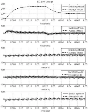
Switching and average models are implemented in a Matlab/Simulink environment. These two different approaches are compared for each case study to evaluate the new linear modeling of the system and its proposed controller.
The standby mode operation performance of the BTB HVDC system is shown in Figure 2-7. The DC capacitor is pre-charged to 200V through the freewheeling diodes then the converter is turned on at t=0 s while the power reference commands are kept at zero. At t=0.025 s a step change in the DC link voltage is applied and the system response is observed. The Id change of the supplier side at the transient periods is unavoidable since it is needed to either charge or discharge the capacitor based on the demand; however, the controller should be able to limit the response within the converter rating. The initial conditions could be adjusted analytically to excite only the particular modes of the system, but the result is shown without considering this fact which may not be practical. It can be also seen that the DC link voltage has no oscillatory behavior due to the pole placement at the real axis. The system states response time in this simulation is shown intentionally equal to the system currently implemented with improved performance in terms of damped waveforms. The controller is capable of achieving faster response time.
Figure 2-7. BTB VSC system standby operation performance with a change in the reference DC link voltage from 250V to 220V.
The operational performance of the system under a reactive power supply is presented in Figure 2-8. The performance is observed at the same initial conditions as before. Each converter now supplies its own system's reactive power demand for instance, to regulate the bus voltage at each respective power system. The rectifier side starts to provide 12 KVAr capacitive reactive power at Iq=-90 A whereas the inverter side provides 12 KVAr inductive
reference value, the demand current requirement is met much faster as designed. The operation is altered at t=0.025s as the reactive power transfer is reversed from 12 KVAr capacitive to 12 KVAr inductive for the rectifier side and vice versa for the inverter side.
The main validation of the model should be proved for the active power transfer. Figure 2-9 shows the operational performance of the BTB HVDC system where the 10.8 KW power (Id=80 A) is transferred from the main to the consumer. In this simulation it is also
shown that while the active power is transferred, each converter can provide either capacitive or inductive reactive power for its respective power system as long as it does not exceed the converter rating. The amount of reactive power is 8.1 capacitive KVAr (Iq=-60 A) for the
rectifier side and 8.1 inductive KVAr (Iq=60 A) for the inverter side.
Figure 2-8. BtB VSC system performance with a change in the reference reactive power command from -12 KVAr to +12 KVAr for the rectifier side and from +12 KVAr to -12
Figure 2-9. BtB HVDC system performance with a change in the reference active power command from zero to 10.8 KW while the rectifier and inverter sides provide -8.1 KVAr and
+8.1 KVAr reactive power respectively.
VSC-Based BTB System Operation under Power Line Faults with
2.5
Existing Controllers
BTB HVDC control system was examined in Section 2.4; now, the performance of the system under common power line faults is considered.
Figure 2-10. Performance of the conventional VSC-based BTB system when a SLG fault occurs in the rectifier side.
of the disturbance rejection of the proposed controller), the oscillatory behavior of the DC link cannot be vanquished with the common controller structure.
Figure 2-11. Performance of the conventional VSC-based BTB system when a SLG fault occurs in the inverter side.
signalling to the rectifier within the fault. Although the main focus remains the power line faults in the inverter side the proposed methods can be applied to the faults in the rectifier side as well. The later will be covered later as the generalized control structure for BTB VSC systems.
Resilient Operation of Vector-Controlled VSC-Based BTB HVDC
2.6
Systems
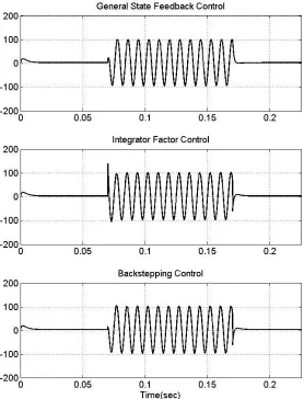
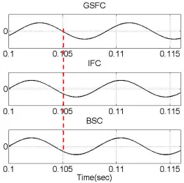
It has been shown in the previous section that conventional control methods are not able to regulate the DC bus voltage of VSC-based HVDC systems under power systems disturbances. This fact is mainly highlighted due to the low switching frequency operation of current semiconductor devices. Therefore, in this section two control structures are proposed that mitigate the DC bus voltage oscillations under power system faults for HVDC applications. These two structures, called “Integral Factor Control (IFC)” and “Backstepping Control (BSC)”, are constructed based on local control of the states. The general idea of these two proposed methods is to create a virtual direct input to control the DC bus voltage dynamics in the time domain.
In the following, for the sake of simplicity (2.3), (2.4) and (2.7) are written with ai
coefficients. The states, inputs, outputs and disturbances are interpreted from (2.10) and presented in (2.15)-(2.17).
1( ) 1 1( ) 2 2( ) 3 1( ) 4 1( )
d s d d
d q
s s s
dI R E V
x t I I a x t a x t a e t a u t
dt L L L
2( ) 2 1( ) 1 2( ) 3 2( ) 4 2( )
q s q q
q d
s s s
dI R E V
x t I I a x t a x t a e t a u t
dt L L L
(2.16)
2 2
3 5 1 1 6 3 7 3
3
3 2 2
( ) DC d d q q DC load ( ) ( ) ( ) ( )
DC DC p DC DC
E I
dV E I V P
x t a e t x t a x t a e t
dt C C R C C
(2.17)
It should be noted that the general control function does not change with the proposed methods in that the rectifier regulates the DC bus voltage and the fault is at the inverter side. Therefore, only the rectifier is considered in the following analysis. The inverter does not see the DC link dynamics in the controller design window.
Method I: Integrator Factor Control (IFC)
2.6.1
As mentioned before, the outputs for rectifier are reactive power and DC link voltage: Iq
and VDC2. The idea is to select the inputs in order to get the desired response. This approach
is first explained for Iq(x2) dynamics, which clarifies the overall controller design procedure.
The objective for the Iq controller is to have decoupled and disturbance rejection
characteristics while it achieves the required response time. This criterion is obtained if its input u2 has the form of (2.18). The first term in this equation is responsible for the response
time of the state and the rest is for decoupling, disturbance rejection and command following in order regardless of the type of the functions. The result of the first order system is shown in (2.19).
3 2
2 2 2 1 2 2 2
4 4
( ) ( ) a ( ) a ( ) ref
u t f x t x t e t t x
a a
2( ) ( 1 4 2) 2 4 2 2ref
x t a a f x a t x (2.19)
The same analogy can be applied to get the input for x1; however, this state should be
controlled so as to maintain the required dynamics for x3, which does not have access to a
direct input. Hence, the input for x1 should have the form of (2.20). The corresponding x1
dynamics are shown in (2.21).
3 2
1 1 1 1 2 1
4 4
( ) ( ) ( ) a ( ) a ( )
u t t f x t x t e t
a a
(2.20)
1( ) ( 1 4 1) ( )1 4 1( )
x t a a f x t a t (2.21)
To create an input as well as cancel out the non-linearity of x3, it is assumed that:
1( ) ( )1 ( )
x t e t t (2.22)
x1(t) in (2.21) is solved as (2.23).
0
1 4 1 1 4 1 1 4 1
1 1 0 4 1
( ) ( ) ( )
( ) ( ) ( )
t
t
a a f t a a f t a a f t
x t x t e e
e a d (2.23)The required input, ω1(t) is then calculated considering (2.22) and (2.23).
1 4 1
11 2
4 1 4 1 1
( ) ( )
( )
( ) ( ) ( )
a a f e t
t t
a e t a e t e t
(2.24)
With the help of the value obtained for the new control input, state x3 in (2.17) is
5
6 3 7 33 ( ) ( )
x t a t a x t a e t (2.25)
7
3 3 3 3 3
5
( )t f x t( ) a e t( ) t xref a
(2.26)
5 3 3 5 3 33 ( ) ref
x t a f x t a t x (2.27)
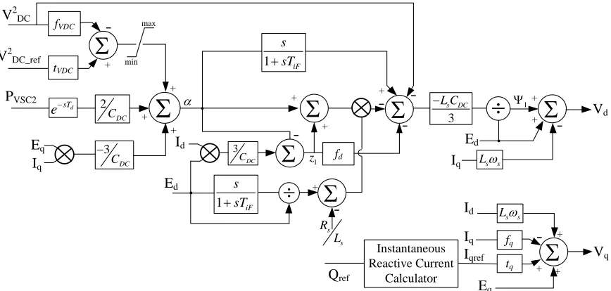
The IFC structure (depicted in Figure 2-12) is different from conventional controller structures for HVDC systems. As shown, the load information and bus voltage are used in this structure to create a required control input. In Figure 2-12 K’ is a function to determine β(t).
Figure 2-12. Proposed Integral Factor Control (IFC) structure for the DC link controller in VSC-based HVDC applications.
The control parameters for IFC are calculated and presented in (2.28) based on the response of the associated modes: λi and λc.
1 6
1 2 3
4 5
6 5 2 1 4 2
2 3 4 5 1 2 ; 3 3 ( ) ; i c
s s i p DC c
s i
a a
f f R L f R C
a a
Para IFC
a a f a a f
t L t
a a (2.28)
V2dc V
2
dc_ref Pload
Integral Factor
Gen.
Modulator
ω1(t)
Iq Iq_ref
Id
VdVq Si
+
-Ed_rec
_
( d rec, )( , )
f E t
Method II: BackStepping Control (BSC)
2.6.2
In control theory, backstepping is a technique for designing controls for nonlinear systems developed around 1990, 42. It is a recursive technique in which one designs feedback controls and finds Lyapunov functions for a set of n-increasingly complex systems, the last system being of interest. Although it is not the intention of this section to deal with the non-linearity of the system now (the linear system has been derived and the fault is at the inverter side), the fundamental basis of the idea can be interpreted as the local control of the states that do not have access to the input. In other words, some states are used as a pseudo-control to stabilize others by introducing some virtual state variables representing the difference between the actual and virtual control.
Since the system considered is a three-state one introduced in (2.10) and x2(Iq) can be
regulated independently by setting u2 as (2.18), the design procedure is confined to a two
state system , x1(Id) and x3(VDC2). Thus, x1 is used to control x3 as shown in (2.29) and (2.30).
The change of the coordinates here to z indicates that x1 should take whatever value is
necessary to make the error z1 null corresponding to achieve the reference z3.
3 3
z x (2.29)
1 1 ( , )3 3
z x z e (2.30)
This method is valid only at the level of the Lyapunov function. The candidate functions selected are based on the energy concept of the DC link capacitor and the interface inductor. Considering the state defined for the DC link voltage as x3=VDC2, it is sufficient to propose
3 3
V z (2.31)
2
1 3 1
1 2
V V z (2.32)
It is remarkable that the key to ensuring the stability of the whole system is not choosing the virtual and actual controls but choosing the correct Lyapunov functions and generating their derivatives negative. The virtual control is chosen as (2.33) to meet the requirement.
7
3 3 3 3 3 8 5 1
8
( , )z e f z a e ,a a e a
(2.33)
The derivative of the proposed Lyapunov functions combining (2.21) and (2.29)-(2.33) results in:
3 8 1 ( 8 3 6) 3
V a z a f a z (2.34)
1 3 1 1
8 1 8 3 6 3 1 4 1( ) 1 3, 3 3, 3 .
V V z z
a z a f a z z a t a z e z e
(2.35)
Choosing the input signal ω1(t) as (2.36) leads to having V1 in the form of (2.37).
1 3 3 3 3
1 1
1 1
4 4 4 4
, ,
( )t f a z a z e z e
a a a a
(2.36)
2
1 1 1 8 1 ( 8 3 6) 3
V f z a z a f a z (2.37)
It is not difficult to determine values for f1 and f3 that render all the derivatives in (2.34)
derivatives are negative for the circuit parameters which ensures the stability of the system in the selected bound. However, the response time is yet to be determined. The desired response time of the virtual states can be simply determined based on several linear methods since they have a simple form of (2.38). The proper consequence can be achieved when the error, z1, goes to zero fast, so the constraint is that the mode associated with z1 should be faster than
that of z3. This fact can be realized in that z1 and z3 have the nature of the current and DC link
voltage respectively, which states that the controller follows the well-known rule in power electronics area to design the current regulator faster than the voltage one. However, there is a major difference in constructing the controller structure. The proposed BSC structure for voltage-sourced converters working as a rectifier of a VSC-based HVDC system is depicted in Figure 2-13. K in this figure is to determine α as shown in (2.33). In this structure the load information should be available to get the desired control input.
1 1 1
8 8 3 6
3 3
0
z f z
a a f a
z z
(2.38)
Figure 2-13. Proposed Back-Stepping Control (BSC) structure for the DC link controller in VSC-based HVDC applications.
V2dc V
2
dc_ref Pload
Virtual Control Gen. Dynamics Control, Decoupling, Disturbance Rejection Ed_rec Modulator α(V2
DC,Pload)
ω1(t)
Iq Iq_ref
Id
VdVq Si