PARTNER
®
Advanced Communications
System
Installation
518-456-162
Comcode 108355231 Issue 1
Notice
Every effort has been made to ensure that the information in this book is complete and accurate at the time of printing. However, information is subject to change.
Federal Communications Commission (FCC) Interference Notice
This equipment has been tested and found to comply with the limits of a Class A or Class B digital device, pursuant to Part 15 of FCC rules. For additional FCC information, see the FCC Notice at the beginning of the PARTNER Advanced Communications System Programming and Use guide.
Canadian Emissions Requirements
This digital apparatus does not exceed the Class A or Class B limits for radio noise emissions from digital apparatus set out in the Radio Interference Regulations of the Industry Canada (IC). For additional IC information, see “IC
Notification and Repair Information” at the beginning of the PARTNER Advanced Communications System Programming and Use guide.
Le present appareil numerique n’emet pas de bruits radioelectriques depassant les limites applicables aux appareils numeriques de la classe A ou de la classe B prescrites dans le Reglement sur le brouillage radioelectrique edicte par le ministere des Industrie Canada. Vous trouverez des renseignements complémitaires dans cette section: “IC
Notification and Repair Information” de PARTNER Advanced Communications System Programming and Use manuel.
Security
Toll fraud, the unauthorized use of your telecommunications system by an unauthorized party (for example, persons other than your company’s employees, agents, subcontractors, or persons working on your company’s behalf) can result in substantial additional charges for your telecommunications services. You are responsible for the security of your system. There may be a risk of toll fraud associated with your telecommunications sytem. You are responsible for programming and configuring your equipment to prevent unauthorized use. Your system manager should read all documents provided with this product to fully understand the features that can introduce the risk of toll fraud and the steps that can be taken to reduce that risk. Lucent Technologies does not warrant that this product is immune from or will prevent unauthorized use of common-carrier telecommunication services or facilities accessed through or connected to it. Lucent Technologies will not be responsible for any charges that result from such unauthorized use. If you suspect you are being victimized by toll fraud and you need technical support or assistance, call the Lucent Technologies National Customer Care Center at 800-628-2888.
Trademarks
Magic on Hold, MLS-34D, MLS-18D, MLS-12D, MLS-12, MLS-6, PARTNER, PARTNER MAIL, PARTNER MAIL VS, SYSTIMAX and TransTalk are registered trademarks of Lucent Technologies. Phillips is a registered trademark of Phillips Screw Company.
Warranty
Lucent Technologies provides a limited warranty for this product. See Appendix B of the PARTNER Advanced Communications System Programming and Use guide.
Ordering Information
The order number for this book is 518-456-162. To order additional books, call 800-457-1235 in the continentinal U.S. or 765-361-5353 outside the continental U.S. For information about ordering other system reference materials,
replacement parts, accessories, and other compatible equipment, refer to “Product Ordering Information” in
Appendix B of the PARTNER Advanced Communications System Programming and Use guide.
Support Telephone Number
Contents
i
Installation
Overview
1A Sample System Setup
1Required Parts
4Installation Guidelines
5■ Telephones and Devices 5
■ Combination Extensions 8
Installation Procedures
10■ Wall-Mounting a Stand-Alone
PARTNER ACS Processor Module 10
■ Wall-Mounting a 2-Slot Carrier and Modules 12
■ Wall-Mounting a 5-Slot Carrier and Modules 16
■ Inserting Batteries in the PARTNER ACS
Processor Module 20
■ Initializing the System 23
■ Connecting Lines and Extensions 25
■ Assembling System Phones 28
■ Connecting Contact Closure, Call Reporting (SMDR),
Paging, and Music-On-Hold Devices 32
■ Connecting a PARTNER-CA48
Intercom Autodialer 35
Equipment Upgrades
37■ Replacing System Modules 37
■ Adding New Modules 44
■ Capacities 49
■ Dimensions and Weights (approx.) 50
Important Safety Instructions
The following list provides basic safety precautions that should always be followed when using your telephone equipment:
1. Read and understand all instructions.
2. Follow all warnings and instructions marked on the product.
3. Unplug all telephone connections before cleaning. DO NOT use liquid cleaners or aerosol cleaners. Use a damp cloth for cleaning.
4. This product should be serviced by (or taken to) a qualified repair center when service or repair work is required.
5. DO NOT use this product near water—for example, in a wet basement location. 6. DO NOT place this product on an unstable cart, stand, or table.
7. Never push objects of any kind into slots or openings as they may touch dangerous voltage points or short out parts that could result in a risk of fire or electric shock. Never spill liquid of any kind on the product.
8. DO NOT use the telephone to report a gas leak in the vicinity of the leak.
9. The product is provided with a three-wire grounding type plug. This is a safety feature. DO NOT defeat the safety purpose of the grounding type plug. DO NOT staple or otherwise attach the power supply cord to building surfaces.
!
CAUTION:
DO NOT block or cover the ventilation slots or openings; they prevent the product from overheating. DO NOT place the product in a separate enclosure unless proper ventilation is provided. DO NOT place the product flat on a surface. The control unit must be wall-mounted.
Additional Safety Instructions for
Installation Personnel
1. DO NOT Install telephone wiring during a lightning storm.
2. DO NOT Install telephone jacks in a wet location unless the jack is specifically designed for wet locations.
3. Never touch uninsulated telephone wires or terminals unless the telephone line has been disconnected at the network interface.
4. Use caution when installing or modifying telephone lines. 5. The control unit must be securely wall mounted.
!
CAUTION:
If any wiring from the extension jacks leaves the building premises, you must install Lucent TechnologiesTM IROB protectors (see “Requirements for Out-of
Building Extensions”).
!
CAUTION:
Use only Lucent Technologies-manufactured PARTNER modules in the PARTNER Advanced Communications System.
!
CAUTION:
Environmental and electrical conditions must meet the requirements as listed in “Specifications”.
1
Installation
Overview
This guide explains how to install the PARTNER® Advanced Communications
System (ACS) Releases 1.0, 1.1, 2.0, 3.0 or later. The information applies to all releases unless otherwise specified.
This guide begins with a sample system setup, then shows the components you need to install the system and gives general guidelines to consider before installation. Next, it provides step-by-step instructions for connecting and testing the components for initial installation and upgrades. Finally, it lists important system specifications. You should ensure that your installation meets all electrical and environmental requirements.
If your company already has modular jacks for all outside lines and extensions, you may be able to use the existing wiring to install the system hardware and connect telephones to the system yourself. To have a Lucent Technologies service technician install and customize your system or change existing wiring, call 800-247-7000 (in the continental U.S. only) or call your Lucent Technologies Representative or local Authorized Dealer.
After installation, refer to the PARTNER Advanced Communications System
Programming and Use guide for programming instructions.
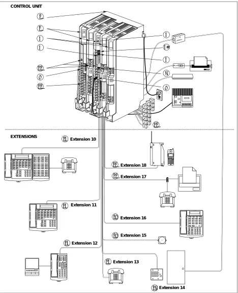
A Sample System Setup
Figure 1 shows a control unit with one PARTNER ACS processor module, one
Control Unit
The control unit consists of these components:
1. 5-Slot Carrier. The carrier channels power to the system and
connects the system modules.
2. 206 and 308EC Modules. Each 206 module has jacks for two
lines and six extensions. Each 308EC module (R2.0 only) has jacks for three lines and eight extensions.
3. 400 Modules. Each 400 module provides four line jacks but no
extensions. Notice that the 400 modules are installed to the right of the 308EC and 206 modules.
4. PARTNER ACS Processor Module. The processor module
contains the software that provides the system’s features, and has jacks for three lines and eight extensions. It also has CONTACT CLOSURE, SMDR, PAGE, and MUSIC-ON-HOLD jacks.
5. Grounding Screw. Attaches a #12 AWG on a #14 AWG solid
copper wire to an approved earth ground.
5a. CONTACT CLOSURE Jack. A Contact Closure Adjunct plugs
directly into this modular jack. Up to two Contact Closure devices such as door locks can be wired to the Adjunct, and users at extensions can control the devices.
6. SMDR Jack. A call reporting (or SMDR–Station Message Detail
Recording) device connects directly to this jack. Lucent Technologies’ Call Accounting Terminal serial printer and box are shown here.
7. PAGE Jack. A loudspeaker paging system plugs directly into
this modular jack. The system is compatible with any Lucent Technologies paging system.
8. Line Jacks. The top two jacks on each 206 module, three jacks
on the ACS and 308EC modules and all four jacks on each 400 module, connect to outside telephone lines.
9. MUSIC-ON-HOLD Jack. Lucent Technologies’ Magic on Hold
is connected to this jack to provide customized music and messages for callers on hold. Other types of audio equipment (including a CD player, cassette player, or stereo receiver) can be connected using an audio cord with an RCA phono plug (not supplied).
If you use equipment that rebroadcasts music or other copyrighted materials, you are required to obtain a license. For more information, see “Music-On-Hold Audio Source” later in this guide.
10. Power LED. The power LED lights when the module is
receiving power.
11. Extension Jacks. The bottom six jacks on each 206 module
and the bottom eight jacks on the ACS and 308EC modules connect inside wiring for telephones and other
telecommunications equipment.
12. Network Interface Jacks. These jacks provide access to
telephone lines from the local telephone company. Each outside line is connected to the system by plugging one end of the line cord into one of these jacks, and the other end into a line jack in the control unit.
Extensions
Various devices—including system phones and
industry-standard devices—can be connected to the modular wall jacks. The modular wall jacks connect to the extension jacks in the control unit by way of the building’s inside wiring.
13. Extension 10: These devices are connected:
■ PARTNER-34D Display Phone. Typically, the receptionist at
extension 10 has a PARTNER-34D display phone like the one shown here. The display shows the time, dialed numbers, the duration of calls, and programming messages.
A display phone is required for system programming at extension 10 or 11, or both. You can use an 18-button display phone if there are no 34-button phones in the system.
■ PARTNER-CA48 Call Assistant Intercom Autodialer. An
Intercom Autodialer is connected to the phone to dial extensions and transfer calls to them with one touch and to see which extensions are busy.
■ Standard Touch-Tone Phone. During a power failure, the
PARTNER-34D phone on extension 10 will not work, but the receptionist can use the standard phone to place calls on line 1.
14. Extension 11: PARTNER-34D Display Phone. Another
PARTNER-34D is connected to programming extension 11. You can program the system from this extension, leaving the receptionist at extension 10 free to handle calls.
15. Extension 12: PARTNER-6 Phone and Answering Machine. A
PARTNER-6 phone and an answering machine are connected to this extension.
16. Extension 13: Standard Phone. A standard phone (such as you
might have in your home) is connected directly to the extension jack.
17. Extension 14: Doorphone. A doorphone is installed at the building
entrance. When someone presses the button on the doorphone, the designated extensions signal. (Any number of extensions can be designated as doorphone alert extensions. For this example, extension 16 is the doorphone alert extension.)
18. Extension 15: Bell. A loud bell is connected directly to this
extension jack. Any line programmed to ring on extension 15 activates the loud bell—to alert users of an incoming call in a large area, such as a warehouse.
19. Extension 16: PARTNER-18D Display Phone. This phone has a
display like the PARTNER-34D phone. For this example, this is the doorphone alert extension and the Contact Closure-enable extension—when someone presses the doorphone button, this phone signals and the user can press a button on the phone signals and the user can press a button on the phone to release the door lock.
20. Extension 17: Fax Machine and Standard Phone. A fax machine
and standard phone share this extension. This lets you have the use of another phone when the fax machine is idle. (You can use a system phone at another extension to monitor fax machine activity—see “FAX Management Feature” under “Using Fax
Machines” in Chapter 4 of the PARTNER Advanced
Communications System Programming and Use guide.)
A Sample System Setup
3
PARTNER 3000
PARTNER 3000 Contact Closure Adjunct
13 14 17 19 15 18 16 20 4 2 Extension 10 Extension 11 Extension 12 Extension 13 Extension 14 Extension 16 Extension 15 Extension 17 1 CONTROL UNIT
21 Extension 18
EXTENSIONS PUSH PFT PFT E X T E N S I O N S L I N E S 7 8 4 5 6 18 19 20 21 22 23 24 25 26 27 28 29 30 31 PARTNER MODULE R1.0 206 8 10 11 3 Feature Intercom ABC 2DEF 3 1 +
–Conf JKL
5MNO 6 TUV 8 WXYZ 9 Transfr Mic HFAI Hold 0 GHI 4 PQRS 7 * # Spkr Intercom Message Ext. Feature Intercom ABC 2DEF 3 1 +
–Conf JKL
5 MNO 6 TUV 8 WXYZ 9 Transfr Mic HFAI Hold 0 GHI 4 PQRS 7 * # Spkr Intercom Message Ext. Feature + –Conf Transfr Mic HFAI Hold ABC 2 DEF 3 1 JKL 5MNO 6 TUV 8WXYZ 9 0 GHI 4 PQRS 7 * # Spkr IntercomIntercom Message Ext. Transfr Feature Intercom ABC 2DEF 3 1 +
–Conf JKL
5 MNO 6 TUV 8WXYZ 9 Mic HFAI Hold 0 GHI 4 PQRS 7 * # Spkr IntercomExt. Message PARTNER 3000 PARTNER L I N E S MODULE R1.0 400 9 10 11 12 PARTNER L I N E S MODULER1.0 400 13 14 16 15 5 5a 12 9 6 7 1 2 3 10 11 12 13 14 15 16 17 POWER RADIO PASS AB 234
6
5MSG2125551212ON78
CD 1 TransTalk On/Off Feat/P ConfGHI PQRS OPER Trans Hold Redial 12 4JKL ABC3DEF 56MNO
TUV 8 0 WXYZ 9 7 Mute ACS Proc.
Required Parts
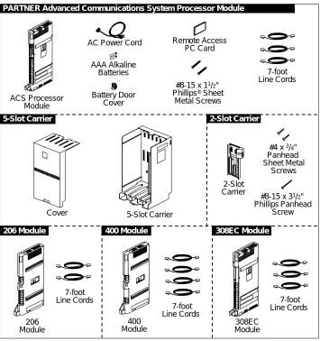
You may have multiple system component packages; Figure 2 shows the package contents. Check your packages to be sure you have the parts shown here (if not, call for support as instructed on the inside front cover of this guide).
NOTE:
The Remote Access PC Card is only included with the PARTNER ACS Release 3.0 or later.
Figure 2. Required Parts
AC Power Cord
Cover 5-Slot Carrier
ACS Processor Module 2-Slot Carrier AAA Alkaline Batteries
PARTNER Advanced Communications System Processor Module
LIN ES PFT EX TEN SI ONS PFT PARTNER MODULE 206 206 Module 7-foot Line Cords 7-foot Line Cords 206 Module 5-Slot Carrier 400
Module Module308EC
7-foot Line Cords 7-foot Line Cords LI NES PFT PARTNER MODULE 400 R1.0 LIN ES PFT
400 Module 308EC Module PARTNER Plus
#8-15 x 11/2"
Phillips® Sheet
Metal Screws
#4 x 3/4"
Panhead Sheet Metal
Screws
#8-15 x 31/2"
Installation Guidelines
5
For a 5-Slot Carrier, you will need to obtain four #12 screws of the appropriate type for the wall and weight of the control unit (a control unit with four 206 modules and a processor module weighs approximately 31 pounds or 14 kilograms). The weight of other configurations may vary slightly.
In addition, if you need modular telephone cords to connect the extension jacks in the control unit to the modular connecting blocks for extensions in the equipment room, short telephone cords or wall plates to wall-mount PARTNER-model phones, or a 355A/355AF adapter and D8W telephone cord to connect a call reporting device, order them before installation.
Refer to “Product Ordering Information” in Appendix B of the PARTNER
Advanced Communications System Programming and Use guide for ordering instructions.
The PARTNER ACS processor module and the 206EC, 308EC, and 400EC modules support the Caller ID feature. These modules are required to provide Caller ID information on system display phones. You must subscribe to Caller ID service from your local telephone company (if it is available), and connect any lines associated with this service to the line jacks on the processor module, the 206EC module, the 308EC module, or the 400EC module. Hereafter, references in this guide to 206 modules include 206E, 206EC, and all 206 modules used with previous releases of the product. Similarly, references to 400 modules include 400E, 400EC, and all 400 modules used with previous releases of the product.
NOTE:
A system display phone is required for programming at extension 10 and/or 11. If you have any 34-button phones in the system, you must use a 34-button display phone to program since an 18-button phone cannot be used to program a 34-button phone. Also, if your system has both
PARTNER-model and MLS-model phones, it is recommended that you use a PARTNER-model display phone at the programming extension.
Installation Guidelines
Telephones and Devices
You can connect the following telephones and devices to the system:
■ PARTNER-model, MLS-model, MDC 9000, and TransTalk® 9000-series
system phones. System phones require at least 2-pair wiring and are
compatible with Lucent Technologies 4-pair SYSTIMAX® wiring.
■ Call Assistant Intercom Autodialers with Busy Indication
(PARTNER-CA48 for PARTNER-model phones or MLS-CA24 for MLS-model phones). You can connect an Intercom Autodialer to the
■ Industry-Standard Devices. Industry-standard devices (including
standard phones) require 1-pair mounting cords; Lucent Technologies D2R mounting cords are recommended.
— Standard Phones. Connect standard touch-tone or rotary dial phones to the system. You can connect a standard phone either alone or combined with a system phone. For more information, see
‘‘Combination Extensions’’ on page 8. Standard phones can be used
to make calls when plugged into any port of the PARTNER ACS processor module.
— Power Failure Operation. During a power failure, system phones will not work because they require power to operate. If you connect standard phones to the first two extensions on the PARTNER ACS processor module, however, users can place and answer outside calls on the first two lines. If you connect a standard phone to the first two extensions on each 308EC module, or the first extension on each 206 module, users can place and answer outside calls on any of these lines. You can connect a standard phone either alone or combined with a system phone. For more information, see ‘‘Combination
Extensions’’ on page 8.
— Hotlines. A hotline extension should be connected to a standard phone, rather than a system telephone, but it can ring any type of phone. An internal hotline phone can also be set up to ring the paging system, so announcements can be made over the loudspeaker. Do not connect a hotline phone to extension 10, 11, or the first two extensions of any 308EC or 206 module; keep these extensions available for power failure use.
For the message-waiting capability, you must connect standard phones with LED-compatible message-waiting lights to a PARTNER ACS processor module, 308EC modules, or Release 3.0 (R3.0) or later 206 modules. This
message-waiting capability does not work with standard phones with neon-type message-waiting lights.
— Auxiliary Equipment. There are a variety of ways to set up fax machines, modems, and answering machines to work with the system.
See Chapter 4 in the PARTNER Advanced Communications System
Programming and Use guide for advice on using this equipment. To connect a telephone and a standard device on the same extension, see
‘‘Combination Extensions’’ on page 8.
— Caller ID Devices. A standard Caller ID device may be installed with the PARTNER system. This arrangement will give a user Caller ID information on a single outside line. If a user desires to use a standard Caller ID device on another line, another Caller ID device must be installed for that line.
Note: The Caller ID device must be connected to the network line
Installation Guidelines
7
station port. If the Caller ID device is to be located next to a PARTNER telephone, an additional wire pair will be needed to extend the line connection to the location where the PARTNER telephone is installed.
To install a Caller ID device for Line 1, do the following:
1. Remove the line 1 cord from the PARTNER line 1 jack on the processor module and install a 267A2 bridging adapter into the line 1 jack.
2. Plug the line 1 cord (that was disconnected in step 1) into one of the jacks on the bridging adapter.
3. Plug the line 1 extended cord (the cord corresponding to the additional wire pair running to the location by the PARTNER telephone) into the other jack on the bridging adapter.
4. At the location where the Caller ID device is being installed, plug the other end of the line 1 extended cord into the Caller ID device. If the device has 2 jacks, plug the cord into the jack labeled LINE.
5. Plug in the power cord (if one exists) for the Caller ID device.
■ Doorphones. You can connect up to two doorphones to the system. Do
not connect doorphones to extension 10, 11, or the first two extensions of any 308EC or 206 module.
■ Contact Closures. You can connect up to two Contact Closure devices,
such as door locks to the Contact Closure Adjunct, so that the devices can be activated from an extension on a user’s desk.
■ Voice Messaging Systems. The system supports the following voice
messaging systems:
— PARTNER Voice Messaging PC Card. For more information on using
this voice messaging system, see the PARTNER Voice Messaging PC
Card Installation, Programming and Use Guide.
— PARTNER MAIL VS® System. This device, which physically
resembles a 206 module, resides in the control unit.
— PARTNER MAIL® System. This device connects to the system through
extension jacks. Do not connect PARTNER MAIL to extension 10, 11, or the first two extensions of any 308EC or 206 module; keep these extensions available for power failure use.
■ Call Reporting Devices. You can connect either a serial printer or a call
accounting device, such as Lucent Technologies Call Accounting Terminal to the SMDR jack on the processor module to record and/or analyze call activity.
■ In-Range Out-of-Building Protectors. To prevent damage from lightning,
Combination Extensions
You can connect a standard device (such as a standard phone or an answering machine) on an extension so that it is by itself, or so that it shares an extension with another piece of equipment (either another standard device or a system
phone). An extension with two devices connected to it is called a combination
extension. (If you combine a standard phone and a system phone on one extension, you may want to turn off the standard phone’s ringer during normal use.)
You cannot install two system phones on the same extension, and the combined REN (Ringer Equivalence Number) of two devices on one extension cannot exceed 2.0. (The REN for a system phone is 0.0.)
NOTE:
The Call Assistant Intercom Autodialer is not regarded as a standard device. This means you can connect a standard device to a system phone that also has an Intercom Autodialer installed.
PARTNER-model system phones have a built-in auxiliary jack so you can connect a standard device directly to the phone without using a bridging adapter, see
“Using a Direct Connection” which follows. If your phone does not have a
built-in auxiliary jack or if you want to connect two standard devices together, you must use a Lucent Technologies 267F2 Bridging Adapter, see “Using a Bridging
Adapter” which follows.
Using a Direct Connection
Figure 3 shows how to connect a standard device directly to a system phone,
using the phone’s built-in auxiliary jack. (Figure 3 is for illustration purposes only; the placement of the jacks on your phone may differ.)
Figure 3. Combination Extension Using Direct Connection
Plug line into jack labeled LINE System Phone
Plug standard device into jack labeled
Installation Guidelines
9
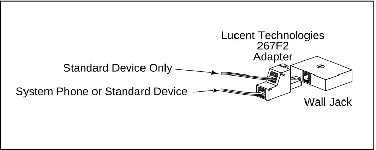
Using a Bridging Adapter
Figure 4 shows how to connect a system phone and a standard device or two
standard devices using a Lucent Technologies 267F2 Bridging Adapter, which can be ordered separately.
Figure 4. Combination Extension Using Bridging Adapter
Lucent Technologies
267F2
Adapter
Wall Jack
Standard Device Only
Installation Procedures
Before installing the system, be sure you read the safety instructions in the front of this guide.
!
WARNING:
!
There are no customer-serviceable components inside the system modules or carrier. There are hazardous voltages within that can cause severe or fatal personal injury. DO NOT OPEN MODULES.
The PARTNER Advanced Communications System can be installed in one of three configurations:
■ Stand-alone PARTNER ACS processor module.
■ 2-Slot Carrier, which can hold up to two modules.
■ 5-Slot Carrier, which can hold up to five modules and includes a cover.
The stand-alone processor module or a carrier and its modules are referred to as the control unit. The control unit must always be wall-mounted. See the following sections for wall-mounting instructions.
Wall-Mounting a Stand-Alone
PARTNER ACS Processor Module
Install the PARTNER ACS processor module within 5 feet (1.5 meters) of a properly grounded wall outlet (not controlled by a switch) and the network interface jacks.
Use the following procedure to wall-mount the module:
1
a. Hold the PARTNER ACSprocessor module against the wall with the line and extension jacks facing left.
Installation Procedures
11
2
a. Insert one of the #8 sheetmetal screws into the screw hole at the top of the module.
b. If you are not installing a second module, insert the other #8 sheet metal screw into the screw hole at the bottom of the module. If you are installing a second module, do not screw in the bottom screw at this time.
c. Tighten the screw or screws until the mounting tracks are
snug against the wall. There
must be a 3/8” (1 cm) gap between the wall and the rest of the module. Do not
overtighten the screw or screws or the module will warp and fail to operate.
3
a. Label the line and extensionjacks as shown.
b. If you are installing a
two-module system, continue with “Wall-Mounting a 2-Slot
Carrier and Modules”;
otherwise, skip to “Inserting
Batteries in the PARTNER ACS Processor Module”.
COMBO COMBO
Wall-Mounting a 2-Slot Carrier and Modules
To wall-mount a 2-Slot Carrier, first follow the instructions in “Wall-Mounting a
Stand-Alone PARTNER ACS Processor Module”.
NOTE:
To add a 308EC module to a PARTNER ACS processor module, the PARTNER ACS processor module must already be mounted on the wall. Before starting, disconnect the power cord from the power jack. If it is not mounted, refer to “Wall-Mounting a Stand-Alone PARTNER ACS
Processor Module” on the previous page for instructions. Then follow the
instructions below.
Use the following procedure to install a 400, 308EC, or 206 or PARTNER MAIL VS module as the second module:
1
Remove the clear plastic protector fromthe connector on the right side of the new 308EC module by grasping the tabs on the ends of the protector and lifting. If you are upgrading from a stand-alone system, also remove the protector from the wall-mounted PARTNER ACS processor module.
2
a. Remove the #8 sheet metal screw orscrews from the bottom of the wall-mounted module or modules.
b. If you are upgrading an existing single module system, skip to Step 4b.
3
If you are replacing the second moduleInstallation Procedures
13
4
a. Slide the second module offthe PARTNER ACS processor module and put it aside.
b. Slide the 308EC module onto the PARTNER ACS processor module, making sure the mounting tracks interlock, as shown in the side view.
5
a. Attach the 2-Slot Carrier to thetop right side of the two modules.
6
Insert the 3-1/2” #8 screw into the bottom of the modules. Tighten it until the mounting tracks of the PARTNER ACS processor module are flush against the wall with a 3/8” (1 cm.) gap between the wall and the rest of the PARTNER ACS processor module. Do not overtighten or the module will warp.7
a. Label the lines and extensionjacks as shown.
b. Connect modular phone cords to the extension jacks, starting at the top extension jack on the PARTNER ACS processor module.
c. Route each cord through the hook on the front of its module.
d. Connect the free end of each phone cord to the modular wall jacks for system extensions.
8
a. Attach one end of a #12 AWGor #14 AWG solid copper wire to the grounding screw on the primary processor module. Note that the length of the wire must not exceed 35 feet (7.6 meters).
b. Route the wire through the hook on the front of the module.
c. Attach the other end of the wire to the approved earth ground, such as building steel or cold water pipe.
L I N E S
E X T E N S I O N S PFT
Installation Procedures
15
9
Press the power cord firmly into the power jack on the carrier. Plug the otherend of the power cord into a properly grounded three-prong wall outlet not controlled by a switch.
!
CAUTION:
The power cord should hang straight down from the connector, flush against the plastic case for the entire length of the board. Do not install the power cord at an angle to the case or with a loop in it.
10
Check the green lights on the fronts of the modules.a. If a single light is out, power down the carrier, reseat the module, then power up the carrier.
b. If both green lights are out, power down the carrier, reseat both modules, then power up the carrier.
c. If the lights are still out, in the continental U.S. call your local Authorized Dealer or the Lucent Technologies Technical Service Center at
800-628-2888. Outside the continental U.S., contact your Lucent Technologies Representative or local Authorized Dealer.
11
Continue with “Inserting Batteries in the PARTNER ACS ProcessorWall-Mounting a 5-Slot Carrier and Modules
Install the 5-Slot Carrier within 5 feet (1.5 meters) of a properly grounded wall outlet (not controlled by a switch) and the network interface jacks. In addition, when you mount the carrier on the wall, leave at least 1 foot (0.3 meter) of clearance at the top and sides, and two feet (0.6 meter) at the front and bottom to ensure proper ventilation.
NOTE:
The location of each module within the carrier is important; place them as instructed in the following procedure.
Use the following procedure to wall-mount the carrier and modules:
1
a. Using the enclosed template,mark the screw locations on the wall.
b. If you are mounting the carrier on plywood, start four #12 screws supplied with the carrier leaving the screw heads extending
approximately 1/4 inch (0.64 cm) from the wall. If you are mounting on drywall, use wall anchors, which must be purchased separately.
2
Before installing any modules,make sure the clear, plastic protector has been removed from the connector area on the rear of each module. To remove the protector, grasp the tabs on the ends of the protector and lift.
IMPORTANT:
308EC and 206 modules must be to the left of any 200 and 400 modules.
Installation Procedures
17
3
a. Verify that the PARTNER ACSprocessor module is in the center slot of the carrier. In the other slots, from left to right, first install the 308EC or 206 modules followed by the 400 or 200 modules.
b. Align the module carefully in the appropriate slot. For proper engagement of the connectors, the module must be inserted straight into the carrier. Once the module is properly seated, firmly push the center of the module until the connectors on the module lock into place, and the module is attached to the rear of the carrier. A slight click indicates the connectors are engaged.
!
CAUTION:
Do not force the module. Use the carrier shelf as a reference and do not tilt, slant or rotate the module. If the module does not insert easily, remove it, clear any obstruction, and reinsert it.
PARTNER3000
Carrier Shelf
YES
Carrier Shelf
4
a. Label the line and extension jacks.b. Connect line and telephone cords to the appropriate jacks on the new module.
c. Route each cord through the hook on the front of its module.
d. Connect the free end of each line cord to the appropriate network interface jack.
e. Connect the free end of each telephone cord to the modular connecting blocks for system extensions.
f. Gather the line and extension cords hanging below the hook and twist tie or wire wrap them.
g. Place the bundle of wires in the indentation on the bottom of the carrier.
5
a. Attach one end of a # 12 AWGor # 14 AWG solid copper wire to the grounding screw on the primary processor module. Note that the length of the wire must not exceed 35 feet (7.6 meters).
b. Route the wire through the hook on the front of the module.
c. Attach the other end of the wire to the approved earth ground, such as building steel or cold water pipe.
6
a. Plug the power cord into a properly grounded three-prong wall outlet notcontrolled by a switch.
b. Power up the control unit by moving the On/Off switch to the “On” position (“—”).
!
CAUTION:
The power cord should hang straight down from the connector, flush against the plastic case for the entire length of the board. Do not install the power
Installation Procedures
19
7
Check the green lights on the fronts of the modules.a. If a single light is out, power down the carrier, reseat the module, then power up the carrier.
b. If multiple lights are out, power down the carrier, reseat the leftmost module that has a light out, then power up the carrier.
c. If the lights are still out, in the continental U.S. call your local Authorized Dealer or the Lucent Technologies Technical Service Center at
800-628-2888. Outside the continental U.S., contact your Lucent Technologies Representative or local Authorized Dealer.
8
Continue with “Inserting Batteries in the PARTNER ACS ProcessorInserting Batteries in the PARTNER ACS
Processor Module
The PARTNER ACS processor module uses two user-replaceable, AAA-size standard alkaline batteries to guard against the loss of system programming in case of a power failure. These batteries will retain the system programming for 45 days to six months, depending on the freshness of the batteries. It is
recommended that you replace the batteries with fresh ones every year.
!
CAUTION:
If this is a new installation, you need to install batteries. Batteries and battery cover are packaged in a separate box. If you are replacing batteries, the old batteries must be removed with the power on or the system’s memory will be lost.
Use the following procedure to replace the batteries:
1
Locate the battery compartment atthe bottom of the PARTNER ACS processor module, below the extension jacks.
2
Push gently on the battery icon(the locking latch) and slide the battery icon up to cover the plus icon; this unlocks the battery assembly.
Battery Compartment
Locking Latch
COMBO COMBO
Unlocked Position Locked
Installation Procedures
21
3
Remove the battery assembly bygently pulling the tab at the bottom of the battery compartment cover.
4
Insert two new AAA-size standardalkaline batteries into the metal battery clips by pushing them straight in, placing the negative (–) end of one battery into the bottom clip and the positive (+) end of the other battery into the top clip.
5
With the locking latch in theunlocked position (battery icon and “minus” icon visible), slide the battery assembly into the
processor module along the battery guides on the inside of the battery compartment.
6
Make sure the battery assembly ispushed in far enough that the edges of the assembly slip behind the plastic housing of the
processor module.
Tab
Push to insert
7
Pressing lightly on the battery icon on the front of the batteryassembly, slide the locking latch downward to secure the assembly in place. The “plus” icon and the battery icon should now be visible on the front of the battery
assembly. This is the locked position.
Unlocked Position
Installation Procedures
23
Initializing the System
NOTE:
The system must be powered down before you insert or remove a PC Card.
The Backup/Restore, Automatic System Answer/Direct Extension Dial, PARTNER VOICE MESSAGING Basics, and software upgrade features of the system all require the use of a PC Card. If you plan to use any of these features, insert the appropriate PC Card in a PC Card Slot before applying power to the system. See
“Inserting or Removing a PC Card” later in this guide.
NOTE:
ACS Release 3.0 includes a PARTNER Remote Access PC Card, which
allows the user to administer the system remotely1 and perform backup and
restore functions. The PARTNER Remote Access PC Card can also be used to upgrade previous versions of PARTNER ACS to Release 3.0.
Before you can use PARTNER VOICE MESSAGING, the PARTNER ACS must be upgraded from Release 1.0 to Release 1.1 or later. PARTNER VOICE MESSAGING does not work with ACS Release 1.0.
To apply the PARTNER ACS to a Release 1.1 or Release 2.0 or later software upgrade, use the following procedure:
1
Insert the PC Card in the PC CardSlot before powering up the system for the first time.
!
WARNING:
!
All other PC Cards must be removed from the processor before initiating an upgrade.
2
Power up the system as describedin the following procedure. While the system upgrades, the bicolor
(red/green) power LED on the processor flashes green and red alternately. When the upgrade has finished (in about 20 seconds), the power LED becomes steady green.
3
Power down the system.4
Remove the PARTNER Remote Access PC Card.NOTE:
For ACS Release 3.0., the PARTNER Remote Access PC Card is used to upgrade the system. This card is also used for remote PC administration and backup/restore and should not be removed or discarded.
5
Re-power the system.To power up the system, use the following procedure:
1
a. If you have a stand-alone or a2-Slot Carrier configuration, skip to Step 1b. If you have a 5-Slot Carrier, move the carrier’s On/Off switch to the “Off” position (“O”).
b. Press the power cord firmly into the power jack on the carrier or stand-alone PARTNER ACS processor module until it locks into place. (See the illustrations on this page for the location of the power jack for each type of configuration.)
c. Plug the other end of the power cord into a properly grounded three-prong wall outlet not controlled by a switch.
!
CAUTION:
Installation Procedures
25
2
Check all green lights on thefronts of the modules. If all the lights are lit, continue with
“Connecting Lines and Extensions”. If any lights are
out, do the following:
a. If a single light is out, power down the control unit, reseat the module, then power up the control unit.
b. If multiple lights are out,
power down the control unit, reseat the leftmost module that has a light out, then power up the control unit.
c. If the lights are still out, call for support as instructed on the inside front cover of this guide.
Connecting Lines and Extensions
If extensions are not wired to any modular jacks, call a qualified service technician.
Use the following procedure to connect lines and extensions:
1
a. Test for a dial tone at thenetwork interface jacks before connecting outside lines to the control unit. For the test, connect a standard phone to the first network interface jack.
b. Lift the handset and listen for a dial tone. (If there is no dial tone, contact your local telephone company before continuing.)
c. Repeat for each network interface jack.
L I N E S PFT
L I N E S PFT
2
a. Connect line cords to the line jacks on the PARTNER ACS processor module and the 308EC, 206, and 400modules. Start at the top with the line jacks on the
PARTNER ACS processor module, and then move to the leftmost 308EC or 206 module. Fill each module before moving to the next module to the right.
b. Route each cord through the hook on the front of the module.
3
Connect the free end of each linecord to the appropriate network interface jack.
4
a. Test the lines—plug a systemphone into extension jack 10. Press the line buttons for each outside line and listen for a dial tone.
b. Repeat for the first extension on each module.
1 2 3
10 11 12
14 15 16 17 13
11 12
14 15 16 17 13
555-13
555-1347
555-1348
555-1349
COMBO
COMBO COMBO
COMBO COMBO
Installation Procedures
27
5
a. Connect modular telephone cordsto the extension jacks, starting at the top extension jack on the PARTNER ACS processor module. When that module is full, move to the leftmost 308EC or 206 module. Fill each module before moving on to the next module to the right.
b. Route each cord through the hook on the front of the module.
c. Connect the free end of each modular telephone cord to the modular wall jacks for system extensions.
d. Dress the wires. Gather the line and extension cords hanging below the hooks of the first two modules and twist tie or wire wrap them. Repeat for the remaining cords. For the 5-Slot Carrier, place each bundle of wires in the indentations cut out of the bottom edge of the carrier.
6
If you have a 5-Slot Carrierconfiguration, install the cover as follows:
a. Make sure all modules are seated properly. The cover will not fit if the modules are not seated properly.
b. To cover the modules, grasp the upper edges of the cover and hold it squarely over the control unit. It is important to install the cover to keep the modules dust-free and the system working efficiently.
c. Place the cover over the modules and make sure it fits firmly in place.
Assembling System Phones
All PARTNER-model system phones are shipped with a stand for either desk-mounting or wall-mounting the phone.
Desk-Mounting
Use the following procedure to desk-mount a phone:
1
a. Gently place the phoneupside down.
b. Route the telephone cord through the hole in the top center of the stand.
2
Insert the tabs on the narrow endInstallation Procedures
29
3
a. While pressing in the tabsthat protrude from the wide end of the stand, lower the stand to the phone.
b. Release the tabs to lock the stand into one of the three positions provided by the openings in the back of the phone.
c. The height of the stand is adjustable to three positions: low, medium, and high. The phone height can be adjusted by moving the locking tabs to a different position.
4
a. If applicable, turn the phoneover.
b. Remove the plastic cover from the phone. Label the button sheet to show any programmed lines or button features, then place the button sheet on the phone so the holes fit over the buttons. Carefully replace the plastic cover.
c. Adjust the swivel display to the desired angle (low, medium, or high).
d. To access the User Instruction
Cards, pull out the tray located under the front of the phone.
ABC 2
DEF 3 1
JKL 5
MNO 6 TUV 8
WXYZ 9 0 GHI 4
PQRS 7
*
#
Conf
Transfr Mic HFAI
Hold Spkr
Feature
Message Intercom
Wall-Mounting
Wall-mounting instructions apply only to PARTNER-model phones. For all other system phones, follow the instructions provided with the phone.
Use the following procedure to wall-mount a phone:
1
a. Reverse the plastic hook thatsits in the earpiece part of the handset cradle.
b. Turn the phone upside down and remove the tray that holds the User Instruction cards: press the tabs on both sides of the tray near the pull out tab while sliding the tray straight out.
2
Holding the stand with the wideedge down, mount the stand on the wall plate using the keyholes on the base of the stand. For proper mounting, the wall plate must be a Lucent Technologies 630B connecting block.
3
a. Plug one end of the telephonecord into the jack in the center of the wall plate.
b. Plug the other end of the telephone cord into the LINE jack on the bottom of the telephone.
Installation Procedures
31
NOTE:It is possible, with selected phone models, to wall-mount the phone in a manner that allows you to retain full functionality of the slide tray and tray card. Use one of the following procedures to accomplish this:
■ If you have an 18/18D, 34D, or DSS phone, the tray can be removed
from the “desk” end of the stand and inserted into the “wall” end. If a 630B wall plate is used, the tray will hang down from the phone.
■ If you do not use the 630B wall plate with the 18/18D and 34D phones,
the tray can slide under the set. To accomplish this, there are two mounting holes on the left and right sides of the stand that will allow the tray to slide underneath.
4
a. To mount the phone on thestand, insert the tabs on the
top of the stand into the middle
set of notches on the top edge of the phone.
b. Make sure the telephone cord is neatly wrapped inside the phone, then rotate the phone down until the bottom edge snaps into position.
5
a. Remove the plastic cover fromthe phone. Label the button sheet to show any
programmed lines or button features, then place the button sheet on the phone so the holes fit over the buttons. Carefully replace the plastic cover.
Connecting and Testing Telephones
Use the following procedure to connect and test a phone:
1
To connect a phone, plug themodular telephone mounting cord into a modular wall jack or directly into a module extension jack. (If you are connecting a standard phone and its mounting cord is loose, try a Lucent Technologies D2R mounting cord instead.)
To install two phones (or other devices) on a single extension jack, see “Combination
Extensions” earlier in this guide.
2
Test the telephone for properoperation. To test the power and lights on a system phone:
a. While the phone is idle, press
and hold the
#
button for fiveseconds.
b. Before releasing the
#
button,lift the handset. All lights should light, the ringer should sound, and (on system display phones only) a test pattern should appear on the display. (If not, call for support as instructed on the inside front cover of this guide.)
c. Replace the handset; the phone is now in normal operating mode.
Connecting Contact Closure, Call Reporting (SMDR),
Paging, and Music-On-Hold Devices
Only steps for connection to the PARTNER ACS processor module are provided here. See the manufacturer’s instructions for more information about installing
L I N E S PFT E X T E N S I O N S PFT 4 5 23 18 19 20 21 22 MODULE206 L I N E S PFT E X T E N S I O N S PFT 6 7 24 25 26 27 28 29 MODULE206 Transfr Feature Intercom
ABC2DEF3 1
+ –Conf JKL5MNO6
TUV8WXYZ9 Mic HFAI Hold 0 GHI 4 PQRS 7 * # Spkr
IntercomExt.Message
Installation Procedures
33
Contact Closure Adjunct
Use the following procedure to connect the Contact Closure:
1
Insert the modular plug into theContact Closure jack, the first jack on the PARTNER ACS processor module.
2
Route the cord as you did for theline and extension cords, then connect the other end of the cord to the jack in the Contact Closure Adjunct.
3
Have a qualified electrician wirethe Contact Closure device or devices to the wiring receptacles in the other end of the Contact Closure Adjunct. See the information shipped with the Contact Closure Adjunct for wiring instructions.
Call Reporting (SMDR) Printer
Use the following procedure to connect the Call Reporting Printer:
1
Insert one end of a D8W modularcord into the SMDR jack, the second jack on the PARTNER ACS processor module.
2
Plug the other end of the cord into a355A adapter, then plug the adapter into the printer’s RS-232C serial port.
Paging System
Use the following procedure to connect and test a phone:
NOTE:
If you connect a paging system from a manufacturer other than Lucent Technologies, a paging interface may be required.
1
Insert the modular plug into thePAGE jack on the PARTNER ACS processor module (located near the middle of the processor, just above the line jacks).
NOTE:
When connecting a paging unit to the PARTNER ACS page jack, a twisted pair cable must be used between the paging unit and the PARTNER ACS processor module.
2
Route the cord as you did for line and extension cords, then connect the otherend of the cord to the paging system.
Music-On-Hold Audio Source
The performance of music over telephone lines is a public performance under United States Copyright law. Accordingly, in order for the performance of that music to be lawful, it must be licensed annually to the user by the copyright owners or their representatives.
You can purchase a Magic-On-Hold system from Lucent Technologies
Installation Procedures
35
1
Insert an RCA phono plug into theMusic-On-Hold jack on the PARTNER ACS processor module (located near the middle of the processor, below the line jacks).
2
Route the cord as you did for lineand extension cords, then connect the other end of the cord to the audio source.
3
Place a call on hold and listen. If you do not hear music at any setting, refer toMusic-On-Hold (#602) and Music-On-Hold Volume (#614) in Chapter 5 of
the PARTNER Advanced Communications System Programming and Use
guide.
Connecting a PARTNER-CA48
Intercom Autodialer
The PARTNER-CA48 Intercom Autodialer is shipped with an adapter, a D8W line cord, a power cord, a power unit, and a button-labeling sheet.
NOTE:
The PARTNER-CA48 Intercom Autodialer can be wall-mounted to work next to a wall-mounted system phone. See the instructions provided with the Autodialer.
1
Plug the adapter into the wall jack.2
a. Plug one end of the D8W linecord into the J1 jack on the adapter.
b. Plug the other end of the D8W line cord into the IN jack on the bottom of the Autodialer.
COMBO COMBO
-
-Feature Intercom
ABC
2 DEF
3 1 +
–Conf JKL
5 MNO
6
TUV
8WXYZ
9 Transfr Mic HFAI
Hold 0
GHI 4
PQRS 7
* #
Spkr Intercom
Message
3
a. Plug the blue-tinted connector (labeled D8AC) of the power cord into the jack on the power unit.!
CAUTION:
Use only the power unit supplied with the PARTNER-CA48 Intercom Autodialer.
b. Plug the other end (clear tinted) of the power cord into the J2 jack on the adapter.
c. Plug the power unit into an electrical outlet.
4
Plug the phone’s modular telephone cord (LINE jack) into the OUT jack on thebottom of the Autodialer.
5
a. Arrange the Autodialer on thedesk next to the phone.
b. Remove the plastic cover from the autodialer and label the button sheet with employee names. Place the button sheet on the Autodialer, then
carefully replace the plastic cover.
c. Adjust the height of the Autodialer to match the system phone.
NOTE:
If you unplug the system phone that is connected to an Autodialer, you must reset the Autodialer. To do so, unplug the D8W line cord (connected to the IN jack on the bottom of the Autodialer) from the J1 jack on the adapter, then plug it back in.
ABC
2
DEF
3 1
JKL 5
MNO 6 TUV 8 WXYZ 9 0 GHI 4 PQ
RS 7
* #
Message
Intercom Intercom
Ext.
Conf Transfr Mic HFAI Hold Spkr
Equipment Upgrades
37
Equipment Upgrades
Replacing System Modules
The procedure for replacing a module depends on your configuration:
Replacing a Stand-Alone PARTNER ACS Processor
Module
!
WARNING:
!
Disconnect the power cord from the power jack on the PARTNER ACS processor module. For an illustration showing the location of the power jack,
see “Initializing the System”earlier in this guide.
1
Check the slack in the wires. Ifthere is not enough slack to remove the module without pulling the line and extension cords free, label and disconnect the wires before continuing.
2
Remove the screws at the top andbottom of the module, and remove the module from the wall.
3
Follow the instructions in“Wall-Mounting a Stand-Alone PARTNER ACS Processor Module” and “Inserting
Batteries in the PARTNER ACS Processor Module”earlier in this
guide.
If you have a...
See...
Stand-alone PARTNER ACS processor module configuration
“Replacing a Stand-Alone PARTNER ACS Processor Module”
2-Slot carrier configuration “Replacing Modules in a 2-Slot Carrier”
5-Slot carrier configuration “Replacing Modules in a 5-Slot Carrier”
4
Connect the line and extension cords one at a time, making sure to place the correct cords into their corresponding jacks on the new module. (See“Connecting Lines and Extensions” earlier in this guide.)
5
Reconnect the power cord.!
CAUTION:
Equipment Upgrades
39
Replacing Modules in a 2-Slot Carrier
!
WARNING:
!
Before starting, verify that you have batteries installed in the PARTNER ACS processor module, and then disconnect the power cord from the power jack on the carrier. For an illustration showing the location of the power jack, see
“Initializing the System”earlier in this guide.
1
Check the slack in the wires. Ifthere is not enough slack to remove the modules without pulling the line and extension cords free, label and disconnect the wires before continuing.
2
Remove the long screw at thebottom of the modules.
3
Remove the screws that attach4
Pull the carrier to the right to remove it.5
a. Slide the top module to the leftto disengage its interlocking mounting tracks from the PARTNER ACS processor module.
b. If you are replacing the PARTNER ACS processor module, skip to Step 7. If you are replacing the top module, continue with Step 6.
6
Mount the new module byfollowing Steps 3 through 8 in
“Wall-Mounting a 2-Slot Carrier and Modules”, earlier in this
Equipment Upgrades
41
7
a. Remove the screw at the top ofthe PARTNER ACS processor module and remove the module from the wall.
b. Mount the new PARTNER ACS processor module by following the instructions in
“Wall-Mounting a
Stand-Alone PARTNER ACS Processor Module” and “Inserting Batteries in the PARTNER ACS Processor Module” earlier in this guide.
c. Remount the top module by following Steps 1 and 3 through 9 in “Wall-Mounting a
2-Slot Carrier and Modules”
earlier in this guide.
8
Connect the line and extension cords one at a time, making sure to place thecorrect cords into their corresponding jacks on the new module. (See
“Connecting Lines and Extensions” earlier in this guide.)
9
Reconnect the power cord.!
CAUTION:
The power cord should hang straight down from the connector, flush against the plastic case for the entire length of the board. Do not install the power cord at an angle to the case or with a loop in it.
Replacing Modules in a 5-Slot Carrier
!
WARNING:
!
Before starting, move the On/Off switch to “off” and unplug the power cord. Verify that you have batteries installed in the PARTNER ACS processor module, and then disconnect the power cord from the wall jack on the carrier.
1
a. Loosen the screw on the lowerfront of the carrier’s cover. Then place one hand on the handle on the lower front and the other hand on the top of the cover.
b. Gently pull the cover up and away from the carrier. Be careful not to break the tabs that attach the cover to the carrier.
2
Before installing a module, makesure the clear, plastic protector has been removed from the connector area on the rear of the module. To remove the protector, grasp the tabs on the ends of the protector and lift.
3
a. Check the slack in the wires. Ifthere is not enough slack to remove the module without pulling the line and extension cords free, label and
disconnect the wires before continuing with Step 3b.
Equipment Upgrades
43
c. If you are replacing a module with one of a different type, make sure that all 400 (or 200) modules are installed to the right of all 308EC or 206 modules, and that the PARTNER ACS processor module remains in the center slot.
d. To insert the replacement, once the module is properly seated, firmly push the center of the module until the connectors on the module lock into place, and the module is attached to the
rear of the carrier. For proper engagement of the connectors, the module must be inserted straight into the carrier. A slight click indicates the connectors are engaged.
!
CAUTION:
Do not force the module. Use the carrier shelf as a reference and do not tilt, slant or rotate the module. If the module does not insert easily, remove it, clear any obstruction, and reinsert it.
4
a. Connect the line and extensioncords one at a time, making sure to place the correct cords into their corresponding jacks on the new module. (See “Connecting Lines
and Extensions” earlier in this
guide.)
b. Reconnect the power cord.
!
CAUTION:
The power cord should hang straight down from the connector, flush against the plastic case for the entire length of the board. Do not install the power cord at an angle to the case or with a loop in it.
c. Move the carrier’s On/Off switch to the “On” position (“—”).
PFT
PFT E X T E N S
I
O N S
L
I
N E S
MODULE 206
PARTNER3000
Carrier Shelf
YES
Carrier Shelf
5
Check that all green lights on the fronts of the modules are lit:a. If a single light is out, power down the control unit, reseat the module, then power up the control unit.
b. If multiple lights are out, power down the control unit, reseat the leftmost module that has a light out, then power up the control unit.
c. If the lights are still out, call for support as instructed on the inside front cover of this guide.
6
a. Make sure all modules are seatedproperly. The cover will not fit if the modules are not seated properly.
b. To replace the cover, grasp it by its upper edges and hold it squarely over the control unit.
c. Place the cover over the modules and make sure it fits firmly in place.
d. Tighten the screw on the lower front of the cover.
Adding New Modules
NOTE:
Use these instructions if you are adding modules to an existing 5-Slot Carrier. If you are upgrading from a stand-alone PARTNER ACS processor module to a 2-Slot Carrier, see “Wall-Mounting a 2-Slot Carrier and
Modules” earlier in this guide for instructions.
!
WARNING:
!
Before starting, verify that you have batteries installed in the PARTNER ACS processor module, and then disconnect the power cord from the power jack on the processor module. For an illustration showing the location of the power jack, see “Initializing the System” in this guide.
L I N E S PFT
L I N E S PFT
Equipment Upgrades
45
1
a. Move the On/Off switch to the“Off” position (“O”).
b. Loosen the screw on the lower front of the carrier’s cover. Then place one hand on the handle on the lower front and the other hand on the top of the cover.
c. Gently pull the cover up and away from the carrier. Be careful not to break the tabs that attach the cover to the carrier.
2
Before installing a module, makesure the clear plastic protector has been removed from the connector area on the rear of the module. To remove the protector, grasp the tabs on the ends of the protector and lift.
3
a. Before you insert the newmodule, make sure that all 400 (or 200) modules are installed to the right of all 308EC or 206 modules. If you need to move a module to accommodate the new one, see “Replacing
System Modules”.
b. Push slowly but firmly in the center of the module until the module locks into place and is attached to the rear of the carrier. Do not force the module. If the module does not insert easily, remove it, clear any obstruction, and reinsert it.
4
a. See “Connecting Lines andExtensions” for instructions for
connecting line and/or
extension jack cords to the new module.
b. Reconnect the power cord.
!
CAUTION:
The power cord should hang straight down from the connector, flush against the plastic case for the entire length of the board. Do not install the power cord at an angle to the case or with a loop in it.
c. Move the On/Off switch to the “On” position (“—”).
5
Check that all green lights on thefronts of the modules are lit:
a. If a single light is out, power down the control unit, reseat the module, then power up the control unit.
b. If multiple lights are out, power down the control unit, reseat the leftmost module that has a light out, then power up the control unit.
c. If the lights are still out, call for support as instructed on the inside front cover of this guide.
6
a. Make sure all modules areseated properly. The cover will not fit if the modules are not seated properly.
b. To replace the cover, grasp it by its upper edges and hold it squarely over the control unit.
c. Place the cover over the modules and make sure it fits firmly in place.
d. Tighten the screw on the lower
L I N E S PFT
L I N E S PFT
Equipment Upgrades
47
Inserting or Removing a PC Card
!
CAUTION:
Before starting, verify that you have batteries installed in the PARTNER ACS processor module.
1
If you have an existing 5-SlotCarrier, move the carrier’s On/Off switch to the “Off” position (“O”). For all types of installations, disconnect the power cord from the power jack. For illustrations showing the location of the power jack on the various configurations, see “Initializing the System” earlier in this guide.
2
If you do not have a 5-Slot Carrier, go to Step 3. If you have a 5-Slot Carrier:a. Loosen the screw on the lower front of the cover. Then place one hand on the handle on the bottom front of the cover and place your other hand on the top of the cover.
b. Gently pull the cover up and away from the carrier. Be careful not to break the tabs that attach the cover to the c