MERLIN LEGEND
®
Communications System
Release 5.0
Maintenance and Troubleshooting
555-650-140
Comcode 108005729
Issue 1
Notice
Every effort was made to ensure that the information in this book was complete and accurate at the time of printing. However, information is subject to change.
See Appendix A, “Customer Support Information,” for important information. It follows Maintenance and Troubleshooting in this binder.
Your Responsibility for Your System’s Security
Toll fraud is the unauthorized use of your telecommunications system by an unauthorized party, for example, persons other than your company’s employees, agents, subcontractors, or persons working on your company’s behalf. Note that there may be a risk of toll fraud associated with your telecommunications system, and if toll fraud occurs, it can result in substantial additional charges for your telecommunications services.
You and your system manager are responsible for the security of your system, such as programming and configuring your equipment to prevent unauthorized use. The system manager is also responsible for reading all installation, instruction, and system administration documents provided with this product in order to fully understand the features that can introduce risk of toll fraud and the steps that can be taken to reduce that risk. Lucent Technologies does not warrant that this product is immune from or will prevent unauthorized use of common-carrier telecommunication services or facilities accessed through or connected to it. Lucent Technologies will not be responsible for any charges that result from such unauthorized use. For important information regarding your system and toll fraud, see Appendix A, “Customer Support Information.”
Federal Communications Commission Statement
This equipment has been tested and found to comply with the limits for a Class A digital device, pursuant to Part 15 of the FCC Rules. These limits are designed to provide reasonable protection against harmful interference when the equipment is operated in a commercial environment. This equipment generates, uses, and can radiate radio frequency energy and, if not installed and used in accordance with the instruction manual, may cause harmful interference to radio communications. Operation of this equipment in a residential area is likely to cause harmful interference, in which case the user will be required to correct the interference at his own expense. For further FCC information, see Appendix A, “Customer Support Information.”
Canadian Department of Communications (DOC) Interference Information
This digital apparatus does not exceed the Class A limits for radio noise emissions set out in the radio interference regulations of the Canadian Department of Communications.
Le Présent Appareil Numérique n’émet pas de bruits radioélectriques dépassant les limites applicables aux appareils numériques de la classe A préscrites dans le réglement sur le brouillage radioélectrique édicté par le ministère des Communications du Canada.
Trademarks
5ESS, ACCUNET, ACCULINK, CONVERSANT, DEFINITY, Magic On Hold, Megacom, MERLIN, MERLIN II, MERLIN LEGEND, MERLIN MAIL, MultiQuest, Music on Hold, PassageWay, and Systimax are registered trade-marks and 4ESS, Lucent Technologies Attendant, AUDIX Voice Power, FAX Attendant System, HackerTracker, MERLIN Identifier, MLX-5, MLX-5D, MLX-10, MLX-10D, MLX-10DP, MLX-16DP, MLX-20L, and MLX-28D, are trade-marks of Lucent Technologies in the US and other countries.
Microsoft and Windows are registered trademarks of Microsoft Corporation.
ProComm and ProComm Plus are registered trademarks of DataStorm Technologies, Inc. Supra, StarSet, and Mirage are registered trademarks of Plantronics, Inc.
UNIX is a registered trademark of UNIX System Laboratories, Inc.
PagePac is a registered trademark of DRACON, a division of Harris Corporation. Okidata is a registered trademark of Okidata Corporation.
NORTEL is a registered trademark and DMS a trademark of Northern Telecom. MCI, Prism, and Vnet are registered trademarks of MCI Communications Corporation.
All Rights Reserved Issue 1
MERLIN LEGEND Communications System Release 5.0 Maintenance and Troubleshooting 555-650-140
Issue 1 June 1997 Contents
Page iii
Contents
Contents iii
IMPORTANT SAFETY INSTRUCTIONS vii
About This Book xi
■ Intended Audience xi
■ How to Use This Book xi
■ Terms and Conventions Used xiii
■ Product Safety Labels xiv
■ Security xv
■ Related Documents xvi
■ How to Comment on This Document xvii
1
Introduction 1-1■ Equipment 1-1
■ On-Site Programming Maintenance 1-3 ■ Remote Programming Maintenance 1-7
■ Using SPM 1-9
■ Preparation for Hardware Maintenance 1-18
■ Maintenance Strategy 1-20
■ Unit Loads 1-30
2
Error Logs, Access Logs, and System Inventory 2-1■ Error Logs 2-1
■ Access Log 2-24
■ System Inventory 2-26
3
Telephone Problems 3-1■ Fixing Telephone Problems 3-2
Maintenance and Troubleshooting 555-650-140 June 1997 Contents
Page iv
■ System Requirements
for Touch-Tone Receivers 3-8
4
Control Unit Problems 4-1■ Backing Up System Programming 4-1
■ Power Supply Problems 4-2
■ Processor Problems 4-12
■ Module Problems 4-34
■ 800 NI-BRI Module Problems 4-78
■ 100D Module Problems 4-103
■ CTI Link Problems 4-118
■ Removing a CTI Link 4-130
■ Carrier Problems 4-132
■ Checking System and Slot Status 4-134
5
Central Office Problems 5-1■ Trunk Errors 5-1
■ Checking Ports 5-8
■ Conclusion of Hardware Maintenance 5-41
A
Customer Support Information A-1■ Support Telephone Number A-1
■ Federal Communications
Commission (FCC) Electromagnetic
Interference Information A-2
■ Canadian Department of Communications (DOC)
Interference Information A-2
■ FCC Notification
and Repair Information A-3
■ Installation
and Operational Procedures A-5
■ DOC Notification
MERLIN LEGEND Communications System Release 5.0 Maintenance and Troubleshooting 555-650-140
Issue 1 June 1997 Contents
Page v
■ Renseignements sur la notification du ministère des Communications
du Canada et la réparation A-9
■ Security of Your System:
Preventing Toll Fraud A-12
■ Toll Fraud Prevention A-14
■ Other Security Hints A-22
■ Limited Warranty
and Limitation of Liability A-28
■ Remote Administration
and Maintenance A-30
B
System Numbering Forms B-1■ Form 2a, System Numbering: Extension Jacks B-2 ■ Form 2b, System Numbering: Digital Adjuncts B-4 ■ Form 2c, System Numbering: Line/Trunk Jacks B-5 ■ Form 2d, System Numbering: Special Renumbers B-6
C
Unit Load Calculation Worksheet C-1■ Unit Load Worksheet C-2
D
Backing Up with a Memory Card D-1■ Card Types D-2
■ Memory Card Formatting D-5
■ Backup D-7
■ Automatic Backup D-12
■ Restore D-20
E
Modifying A Release 2.1 or EarlierProcessor Key Mode E-1
F
NI-1 BRI Provisioning F-1Maintenance and Troubleshooting 555-650-140 June 1997 Contents
Page vi
■ Siemens SSC EWSD Switch Translations F-32
GL
Glossary GL-1IMPORTANT SAFETY INSTRUCTIONS
Page vii
MERLIN LEGEND Communications System Release 5.0 Maintenance and Troubleshooting
Issue 1 June 1997
MERLIN LEGEND Communications System Release 5.0 Maintenance and Troubleshooting 555-650-140
Issue 1 June 1997
IMPORTANT SAFETY INSTRUCTIONS
The exclamation point in an equilateral triangle is intended to alert the user to the presence of important operating and maintenance (servicing) instructions in the literature accompanying the product.
When installing telephone equipment, always follow basic safety precautions to reduce the risk of fire, electrical shock, and injury to persons, including:
■ Read and understand all instructions.
■ Follow all warnings and instructions marked on or packed with the
product.
■ Never install telephone wiring during a lightning storm.
■ Never install a telephone jack in a wet location unless the jack is
specifically designed for wet locations.
■ Never touch uninsulated telephone wires or terminals unless the
telephone wiring has been disconnected at the network interface.
■ Use caution when installing or modifying telephone lines.
■ Use only Lucent Technologies-manufactured MERLIN LEGEND
Maintenance and Troubleshooting 555-650-140 June 1997
IMPORTANT SAFETY INSTRUCTIONS
Page viii
■ Use only Lucent Technologies-recommended/approved MERLIN
LEGEND Communications System accessories.
■ If equipment connected to the analog extension modules (008, 408, 408
GS/LS) or to the MLX telephone modules (008 MLX, 408 GS/LS-MLX) is to be used for in-range out-of-building (IROB) applications, IROB protectors are required.
■ Do not install this product near water, for example, in a wet basement
location.
■ Do not overload wall outlets, as this can result in the risk of fire or
electrical shock.
■ The MERLIN LEGEND Communications System is equipped with a
3-wire grounding-type plug with a third (grounding) pin. This plug will fit only into a grounding-type power outlet. This is a safety feature. If you are unable to insert the plug into the outlet, contact an electrician to replace the obsolete outlet. Do not defeat the safety purpose of the grounding plug.
■ The MERLIN LEGEND Communications System requires a
supplementary ground.
■ Do not attach the power supply cord to building surfaces. Do not allow
anything to rest on the power cord. Do not locate this product where the cord will be abused by persons walking on it.
■ Slots and openings in the module housings are provided for ventilation.
To protect this equipment from overheating, do not block these openings.
■ Never push objects of any kind into this product through module
openings or expansion slots, as they may touch dangerous voltage points or short out parts, which could result in a risk of fire or electrical shock. Never spill liquid of any kind on this product.
■ Unplug the product from the wall outlet before cleaning. Use a damp
MERLIN LEGEND Communications System Release 5.0
Maintenance and Troubleshooting 555-650-140 June 1997Issue 1
IMPORTANT SAFETY INSTRUCTIONS
Page ix
■ Auxiliary equipment includes answering machines, alerts, modems, and
fax machines. To connect one of these devices, you must first have a Multi-Function Module (MFM).
■ Do not operate telephones if chemical gas leakage is suspected in the
area. Use telephones located in some other safe area to report the trouble.
!
WARNING:
!
■ For your personal safety, DO NOT install an MFM yourself.
■ ONLY an authorized technician or dealer representative shall install, set options, or repair an MFM.
■ To eliminate the risk of personal injury due to electrical shock, DO NOT attempt to install or remove an MFM from your MLX telephone. Opening or removing the module cover of your telephone may expose you to dangerous voltages.
Maintenance and Troubleshooting 555-650-140 June 1997
IMPORTANT SAFETY INSTRUCTIONS
About This Book
Page xi Intended Audience
MERLIN LEGEND Communications System Release 5.0 Maintenance and Troubleshooting
Issue 1 June 1997
MERLIN LEGEND Communications System Release 5.0 Maintenance and Troubleshooting 555-650-140
Issue 1 June 1997
About This Book
The MERLIN LEGEND® Communications System is an advanced digital
switching system that integrates voice and data communications features. Voice features include traditional telephone features, such as Transfer and Hold, and advanced features, such as Group Coverage and Park. Data features allow both voice and data to be transmitted over the same system wiring.
Intended Audience
This book provides detailed information about system and telephone trouble reports and troubleshooting operations. It is intended for use by qualified field technicians who are responsible for system maintenance and troubleshooting, and as a reference by anyone needing such information, including support personnel, sales representatives, and account executives.
How to Use This Book
Maintenance and Troubleshooting 555-650-140 June 1997
About This Book
Page xii How to Use This Book
Refer to the following documentation for additional information:
■ Equipment and Operations Reference provides detailed information on
system hardware, telephones, and other equipment. (Not updated since Release 3.0).
■ Feature Reference provides details on the features of the
communications system.
■ System Planning provides procedures and forms for planning a system
for installation.
■ System Programming gives procedural instructions for programming
system features.
■ Users’ guides and Operators’ Guides give procedural instructions for
programming and using telephone features.
“Related Documents,” later in this section, provides a complete list of system documentation together with ordering information.
In the USA only, Lucent Technologies provides a toll-free customer Helpline (1
MERLIN LEGEND Communications System Release 5.0
Maintenance and Troubleshooting 555-650-140 June 1997Issue 1
About This Book
Page xiii Terms and Conventions Used
Terms and Conventions Used
In this document, the terms in the following list are used in preference to other, equally acceptable terms for describing communications systems.
Lines, Trunks and Facilities
Facility is a general term that designates a communications path between a
telephone system and the telephone company central office. Technically a trunk
connects a switch to a switch, for example the MERLIN LEGEND
Communications System to the central office. Technically, a line is a loop-start facility or a communications path that does not connect two switches (for example, an intercom line or a Centrex line). However, in actual usage, the terms line and trunk are often applied interchangeably. In this book, we use
line/trunk and lines/trunks to refer to facilities in general. Specifically, we refer to
digital facilities. We also use terms such as personal line, ground-start trunk, Direct Inward Dialing (DID) trunk, and so on. When you talk to your local telephone company central office, ask them which terms they use for the specific facilities they connect to your system.
Some older terms have been replaced with newer terms. The following list shows the old term on the left and the new term on the right:
trunk module line/trunk module
trunk jack line/trunk jack
station extension
station jack extension jack
analog data station modem data station
digital data station terminal adapter
7500B data station terminal adapter
analog voice and analog data station analog voice and modem data
digital voice and analog data station MLX voice and modem data
analog data only station modem data only station
digital data only station terminal adapter only station
7500B data only station terminal adapter only station
digital voice and digital data station MLX voice and terminal
Maintenance and Troubleshooting 555-650-140 June 1997
About This Book
Page xiv Product Safety Labels
MLX voice and 7500B data station MLX voice and terminal
adapter station
Typographical Conventions
Certain type fonts and styles act as visual cues to help you rapidly understand the information presented:
Product Safety Labels
Throughout these documents, hazardous situations are indicated by an exclamation point inside a triangle and the word CAUTION or WARNING.
Example Purpose
It is very important that you follow these steps. You must attach the wristband before touching the connection.
Italics indicate emphasis.
The part of the headset that fits over one or both ears is called a
headpiece.
Italics also set off special terms.
If you press the Feature button on an MLX display telephone, the display lists telephone features you can select. A programmed Auto Dial button gives you instant access to an inside or outside number.
The names of fixed-feature,
factory-imprinted buttons appear in bold. The names of programmed buttons are printed as regular text.
Choose Ext Prog from the display screen.
Plain constant-width type indicates text that appears on the telephone display or personal computer (PC) screen.
MERLIN LEGEND Communications System Release 5.0
Maintenance and Troubleshooting 555-650-140 June 1997Issue 1
About This Book
Page xv Security
!
WARNING:
!
Warning indicates the presence of a hazard that could cause death or severe personal injury if the hazard is not avoided.
!
CAUTION:
Caution indicates the presence of a hazard that could cause minor personal injury or property damage if the hazard is not avoided.
Security
Certain features of the system can be protected by passwords to prevent unauthorized users from abusing the system. You should assign passwords wherever you can and limit knowledge of such passwords to three or fewer people.
Nondisplaying authorization codes and telephone numbers provide another layer of security. For more information, see Appendix A, “Customer Support
Information” following Maintenance and Troubleshooting.
Throughout this document, toll fraud security hazards are indicated by an exclamation point inside a triangle and the words Security Alert.
!
Security Alert:
Maintenance and Troubleshooting 555-650-140 June 1997
About This Book
Page xvi Related Documents
Related Documents
In addition to this book, the documents listed below are part of the
documentation set. Within the continental United States, these documents can be ordered from the Lucent Technologies BCS Publications Center by calling 1 800 457-1235.
Document No. Title
System Documents
555-650-110 Feature Reference
555-650-111 System Programming
555-650-112 System Planning
555-650-113 System Planning Forms
555-650-116 Pocket Reference
555-650-118 System Manager’s Guide
Telephone User Support
555-650-122 MLX-5D*, MLX-10D*, MLX-10DP*, MLX-28D*, and
MLX-20L* Display Telephones User’s Guide
555-630-150 MLX-5D, MLX-10D and MLX-10DP Display Telephone
Tray Cards (5 cards)
555-630-152 MLX-28D and MLX-20L Telephone Tray Cards (5 cards)
555-650-124 MLX 10* Nondisplay Telephone User’s Guide
555-630-151 MLX-5 and MLX 10 Nondisplay Telephone Tray Cards
(6 cards)
555-630-155 MLX-16DP Display Telephone Tray Cards (5 cards)
555-650-120 Analog Multiline Telephones User’s Guide
555-650-126 Single-Line Telephones User’s Guide
555-650-138 MDC 9000 and MDW 9000 Telephones User's Guide
System Operator Support
555-650-134 MLX Direct-Line Consoles Operator’s Guide
555-650-132 Analog Direct-Line Consoles Operator’s Guide
555-650-136 MLX Queued Call Console Operator’s Guide
Miscellaneous User Support
555-650-130 Calling Group Supervisor’s Guide
MERLIN LEGEND Communications System Release 5.0
Maintenance and Troubleshooting 555-650-140 June 1997Issue 1
About This Book
Page xvii How to Comment on This Document
How to Comment on This Document
We welcome your comments, both positive and negative. Please use the feedback form on the next page to let us know how we can continue to serve you. If the feedback form is missing, write directly to:
Documentation Manager Lucent Technologies 211 Mount Airy Road Room 2W226
Basking Ridge, NJ 07920
Document No. Title
Documentation for Qualified Technicians
555-650-140 Installation, Programming & Maintenance (IP&M) Binder
[consists of Installation, System Programming & Maintenance (SPM), Maintenance & Troubleshooting]
Toll Fraud Security
Maintenance and Troubleshooting 555-650-140 June 1997
About This Book
Introduction
Page 1-1 Equipment
MERLIN LEGEND Communications System Release 5.0 Maintenance and Troubleshooting
Issue 1 June 1997
MERLIN LEGEND Communications System Release 5.0 Maintenance and Troubleshooting 555-650-140
Issue 1 June 1997
1
1
Introduction
The purpose of maintenance is to detect, report, and clear problems quickly with minimal disruption of service. The system attempts to isolate each problem to a single replaceable unit, whenever possible, by running automatic tests. Errors that it cannot automatically correct are usually recorded in error logs. Most troubleshooting relies on checking the error logs and interpreting them, using Table 2-2, "Error Codes", in Chapter 2.
Equipment
To perform maintenance, you need a maintenance terminal and some additional tools, all of which are defined below.
Maintenance Terminal
Whether you perform on-site or remote maintenance, you need a maintenance terminal:
■ For on-site maintenance, you can use either an MLX-20L system
console or a PC with System Programming and Maintenance (SPM) software.
Maintenance and Troubleshooting 555-650-140 June 1997
Introduction
Page 1-2 Equipment
Detailed information about system programming is included in System
Programming and in System Programming and Maintenance (SPM).
You can use either a DOS PC or a Master Controller (MCII or MCIII) to run SPM. To connect a PC to the control unit, you need a 355AF adapter and a D8W-87 cord.
NOTE:
On-site programming maintenance is preferred if it is feasible; remote programming overrides on-site programming, except when on-site backup or restore is in progress. See ‘‘On-Site Programming Maintenance’’ and
‘‘Remote Programming Maintenance’’, later in this chapter, for details.
Tools
In addition to the maintenance terminal, you need the following tools:
■ EIA breakout box
■ Digital voltmeter (KS-20599 or equivalent)
■ 110/66-type punchdown tool
■ Dracon TS21 or equivalent touch-tone telephone for testing
■ Assorted flathead and Phillips-head screwdrivers
■ Long-nosed and regular pliers
■ Wrist grounding strap
■ Replacement parts recommended by your technical support organization
!
CAUTION:
MERLIN LEGEND Communications System Release 5.0
Maintenance and Troubleshooting 555-650-140 June 1997Issue 1
Introduction
Page 1-3 On-Site Programming Maintenance
On-Site Programming Maintenance
You can perform on-site maintenance with an MLX-20L console or a PC with SPM software. This book provides maintenance instructions from the console. If
you are using a PC, refer to System Programming and Maintenance (SPM) for
details. If you use the UNIXSystem, see the documentation for Integrated
Solution Ill (IS III).
Setting Up the MLX-20L Console
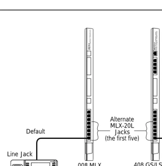
To connect an MLX-20L console to the control unit, follow the steps below. Refer to Figure 1-1.
Plug one end of a D8W-87 cord into one of the first five jacks on the leftmost 008 MLX module or 408 GS/LS-MLX module.
The first MLX jack is the default. If it is already being used for the attendant console, choose another jack. If one of the jacks is already being used for system programming or maintenance, use that jack. Only one jack at a time can be used for system programming or maintenance.
Plug the other end of the D8W-87 cord into the LINE jack on the underside of the MLX-20L console.
MLX-20L Failure
If the MLX-20L console does not work, follow the steps below.
Replace the MLX-20L console with one that is known to be working (if available).
Maintenance and Troubleshooting 555-650-140 June 1997
Introduction
Page 1-4 On-Site Programming Maintenance
If the trouble clears, replace the original D8W-87 cord.
MERLIN LEGEND Communications System Release 5.0
Maintenance and Troubleshooting 555-650-140 June 1997Issue 1
Introduction
Page 1-5 On-Site Programming Maintenance
Figure 1-1. Setting Up the MLX-20L Console 408 GS/LS4 GS or LS Outside Lines/8 MLX (Digital) T
elephones v v Volume Feature HFAI Mute Speaker Transfer Conf Drop Hold ABCDEF GHIJKLMNO PQRSTUVWXYZ OPER
1 2 3
4 5 6
7 8 9
0# * MLX-20L Home Menu More Inspct Default Default
Line Jack Line Jack
008 MLX 408 GS/LS-MLX 008 MLX8 MLX (Dighital) T
elephones
➔
TEL/OTHER LINE DSS Alternate MLX-20L Jacks (the first five)Underside of the MLX-20L Console v v Volume Feature HFAI Mute Speaker Transfer Conf Drop Hold ABCDEF GHIJKLMNO PQRSTUVWXYZ OPER
1 2 3
4 5 6
7 8 9
0# * MLX-20L Home Menu More Inspct v v Volume Feature HFAI Mute Speaker Transfer Conf Drop Hold ABCDEF GHIJKLMNO PQRSTUVWXYZ OPER
1 2 3
4 5 6
7 8 9
Maintenance and Troubleshooting 555-650-140 June 1997
Introduction
Page 1-6 On-Site Programming Maintenance
Setting Up the PC
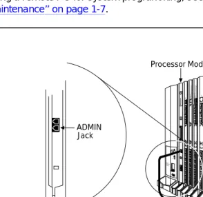
Plug a PC into the ADMIN jack on the processor module as shown in If you are
using a remote PC for system programming, see ‘‘Remote Programming
Maintenance’’ on page 1-7.
Figure 1-2. Setting Up the PC
CAUTION POWER
ON OFF
AG INPUT
FRGND Turn off power before inserting or removing modules
408 GS/LS44GS or LS Outside Lines/8 Analog
Telephones
(ATL)
408 008 MLX 8 MLX (Digital)
Telephones
012
PROCESSOR
IO
87 65432
1
355 AF Adapter
D8W
EIA-232-D ADMIN
Jack
MERLIN LEGEND Communications System Release 5.0
Maintenance and Troubleshooting 555-650-140 June 1997Issue 1
Introduction
Page 1-7 Remote Programming Maintenance
Remote Programming Maintenance
Remote maintenance allows you to support the system from an off-premises location. You can check error logs and system status and restart the system remotely.
To perform remote maintenance, you need a PC with SPM software, a tip/ring telephone, and a 1200-bps modem. Beginning with Release 3.0, a 2400-bps modem may also be used.
Considerations
Review the following points before you begin remote maintenance procedures.
■ Remote maintenance overrides on-site maintenance and programming,
except when on-site backup or restore is in progress. Before you perform remote maintenance, notify the customer’s system manager.
■ You can perform remote maintenance and programming only from a
DOS PC, not from the UNIX environment. If you are running SPM under IS III, you cannot perform remote maintenance.
■ Line noise can cause the SPM screen to display unpredictable results. If
this occurs, hang up and redial.
NOTE:
Maintenance and Troubleshooting 555-650-140 June 1997
Introduction
Page 1-8 Remote Programming Maintenance
Setting Up Equipment for Remote
Maintenance
To set up equipment for remote maintenance, follow the steps below while referring to Figure 1-3 and to Installation.
Connect the PC and modem.
■ If you have an external modem, use an EIA-232-D cable.
■ If you have an internal modem, the connection is already
established.
Use a D8W cord to connect the modem to a T/R trunk jack.
MERLIN LEGEND Communications System Release 5.0
Maintenance and Troubleshooting 555-650-140 June 1997Issue 1
Introduction
Page 1-9 Using SPM
Figure 1-3. External Modem Setup
Using SPM
For more information on using SPM, see System Programming and
Maintenance.
Starting SPM
The procedure for accessing SPM differs slightly, depending on whether your PC is connected directly or by modem to the control unit.
With a Direct Local Connection
To access SPM when your PC is connected directly to the control unit, follow the steps below.
PC running SPM
EXTERNAL MODEM
T/R telephone EIA-232-D
LINE jack
T/R jack
PHONE jack D8W cord
Maintenance and Troubleshooting 555-650-140 June 1997
Introduction
Page 1-10 Using SPM
If you do not have a hard drive, insert the SPM diskette into Drive A and switch to Drive A if it is not already the current drive.
Start the SPM program.
Type SPM. The SPM Welcome screen appears, as shown below.
Console Display/Instructions Additional Information PC Press any key.
Select an option by pressing one of the function keys.
With a Local or Remote Modem Connection
When the equipment is set up, you can perform remote maintenance by dialing the remote processor’s built-in 2400/1200-bps modem. You can dial the modem directly or call the system operator and request to be transferred to the modem. Both procedures are explained below.
Dialing the System Operator
If you do not know the remote access trunk number, dial the number for the customer’s system. To dial the operator, follow the steps below.
Start SPM. When the Welcome message appears, press any key.
Welcome to SPM If the main menu (see Step 4) does
The MERLIN LEGEND not appear, or if the information on
System Programming the screen is garbled, press any
& Maintenance Utility key again.
Please press any key to continue: Version X.xx
SPM Main Menu Menu: Select Function
Sys Pro-gram
Mainte-nance
Backup Restore
Boards Pass-Thru
Print Opts Password
MERLIN LEGEND Communications System Release 5.0
Maintenance and Troubleshooting 555-650-140 June 1997Issue 1
Introduction
Page 1-11 Using SPM
Enter the command to put the modem in originate mode (this command varies depending on the type of modem you are using).
Pick up the handset on the T/R telephone and dial the customer’s system operator (the Listed Directory Number for the customer’s system).
When the attendant answers the call, explain what you are doing and ask for any passwords you may need; then ask the operator to transfer you to the modem by pressing the Transfer button and then dialing *10.
NOTE:
If the password is not known, check the System Information Report or ask to speak with the system manager.
You can change the password without knowing the old password only when you perform on-site maintenance through the ADMIN jack.
When you hear the modem tone, hang up.
If nothing appears on the SPM screen, press 2.
Enter the password.
When the Password: prompt appears, type the password (do not press
2). The SPM main menu appears, and you are ready to proceed
with remote maintenance.
Dialing the Modem Directly
To dial the modem directly, follow the steps below.
Start SPM. When the Welcome message appears, press any key.
Maintenance and Troubleshooting 555-650-140 June 1997
Introduction
Page 1-12 Using SPM
Pick up the handset on the T/R telephone and dial the remote access trunk number.
This is possible only if a trunk is programmed as a dedicated trunk for remote access to the built-in modem.
If the dial tone begins with three short tones followed by a steady tone, dial the remote access barrier code from the T/R telephone; otherwise, go to Step 5.
If you do not know the remote access barrier code, contact the customer’s system manager, or check Form 3a, Incoming Trunks: Remote Access. If the system accepts the barrier code, you hear ringing followed by dial tone.
NOTE:
You can change the barrier code without knowing the old one only when you perform on-site maintenance through the ADMIN jack.
Connect to the modem on the remote system.
When you hear dial tone, dial *10.
When you hear the modem tone, hang up.
MERLIN LEGEND Communications System Release 5.0
Maintenance and Troubleshooting 555-650-140 June 1997Issue 1
Introduction
Page 1-13 Using SPM
Console Display/Instructions Additional Information PC Enter the password.
Select an option.
NOTE:
If you do not know the password, check the System Information Report or ask to speak with the system manager.
You can change the password without knowing the old password only when you perform on-site maintenance through the ADMIN jack.
Enter Password: Type the remote access password. The password you enter does not appear as you type it.
SPM Main Menu Press one of the function keys.
Menu: Select Function
Sys Pro-gram
Mainte-nance
Backup Restore
Boards Pass-Thru
Print Opts Password
Maintenance and Troubleshooting 555-650-140 June 1997
Introduction
Page 1-14 Using SPM
The SPM Display
SPM screens simulate the MLX-20L console (see Figure 1-4).
Figure 1-4. The SPM Display
Each SPM screen includes a 7-line by 24-character console simulation window that corresponds to the display area of the MLX-20L telephone. To the right and left of this console simulation window are columns, listing the keys that
correspond to similarly located buttons on the MLX-20L telephone.
The 10 function keys, identified on screen as through , are used to
select screen options. When a screen displays several choices, press the function key identified by the label next to your choice. (If you were working on the console you would press the telephone button next to your choice.)
Below the console simulation window are 20 simulated line buttons. Using D
MERLIN LEGEND Communications System Release 5.0
Maintenance and Troubleshooting 555-650-140 June 1997Issue 1
Introduction
Page 1-15 Using SPM
A list of labels on the right side of the screen shows key combinations that
correspond to buttons on the MLX-20L telephone. Table 1-1 describes the
function of PC keys within SPM.
Continued on next page
Table 1-1. Function of PC Keys in SPM
PC Key Console SPM Function
H Home Quit. Exit from SPM and return to the DOS prompt
when you have finished system programming. If you are using a modem, the call is disconnected.
E Menu Return to the SPM Main Menu.
U More Display more menu items (when there is an
additional screen and the > symbol appears next to the key).
D Inspct Show the current information that has been programmed for a feature or button.
! 0 Drop Stop. Enter a stop in a speed dialing sequence.
This combination also deletes an entry in a field in any screen except one in which you are entering a speed dialing sequence.
! & Conf Flash. Enter a switchhook flash in a speed dialing
sequence.
! # n/a TopSP. Return to the top of the System
Programming menu.
! ( Hold Pause. Enter a pause in a speed dialing sequence.
! 5 n/a Convert. Convert a backup file from an earlier
Maintenance and Troubleshooting 555-650-140 June 1997
Introduction
Page 1-16 Using SPM
Table 1-1 Continued
PC Key Console SPM Function
# n/a Help. Display a help screen about SPM operations. To
exit from Help, press E.
# n/a Reset. Reset the communications port. For example,
if the information on the screen is garbled, try exiting from and then re-entering the screen. If the screen
remains garbled, use # + to clear the screen
and return to the SPM Welcome screen. Note that
using # + drops the modem connection.
# n/a Browse. View print reports saved with Print Opts.
# n/a Escape to shell. To use this key in sequence, you
must set DEBUG=1 in the SPM configuration file ams.cfg. You can then use this key sequence to execute DOS (or UNIX system) commands. To return to SPM, type exit.
2 Enter This key on your PC can be used instead of
(Enter) when Enter appears as a choice in the
7-by-24 console simulation window.
" Backspace " can be used instead of when it appears as a choice in the 7-by-24 console simulation window.
$ Delete The $ key on your PC can be used instead of (Delete) when it appears as a choice in the 7-by-24 console simulation window.
TBLR n/a The up, down, left, and right arrow keys can be used
MERLIN LEGEND Communications System Release 5.0
Maintenance and Troubleshooting 555-650-140 June 1997Issue 1
Introduction
Page 1-17 Using SPM
Exiting SPM
To exit SPM, follow these steps.
Return to the System Programming menu.
If the display gives directions for returning to the main menu, follow the directions. If not, press (Exit) to return to the previous menu.
Continue to press (Exit) until the main menu appears.
Console Display/Instructions Additional Information PC
Select the Quit option.
SPM Main Menu Press the H key.
Menu: Select Function
Sys Pro-gram
Mainte-nance
Backup Restore
Boards Pass-Thru
Print Opts Password
Maintenance and Troubleshooting 555-650-140 June 1997
Introduction
Page 1-18 Preparation for Hardware Maintenance
Preparation for Hardware
Maintenance
If you are performing on-site hardware maintenance, first remove the control unit housing (the cover of the control unit), then disconnect the AC power.
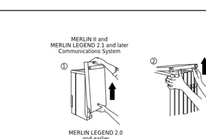
Removing the Control Unit Housing
To remove the control unit’s housing, see Figure 1-5.
■ If you have a MERLIN II Communications System or a MERLIN
LEGEND Communications System (Release 2.1 or later):
1. Pull the bottom front of the housing towards you. When it releases, remove it by lifting up as shown in Figure 1-5.
2. Remove the top cover from each carrier by pushing it straight up from the front.
■ If you have a MERLIN LEGEND Communications System (Release 2.0
or earlier):
1. Pry the clips from the housing on both sides of the control unit; use a screwdriver if they are difficult to remove.
2. Carefully pull the housing towards you.
NOTE:
MERLIN LEGEND Communications System Release 5.0
Maintenance and Troubleshooting 555-650-140 June 1997Issue 1
Introduction
Page 1-19 Preparation for Hardware Maintenance
Figure 1-5. Removing the Control Unit Housing
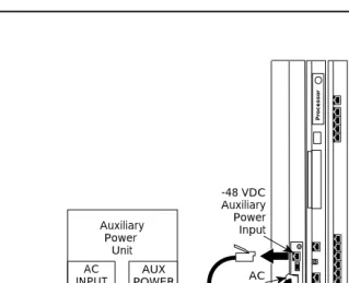
Disconnecting AC Power
To disconnect the AC power, see Figure 1-6, and follow the steps below.
Disconnect the AC power to each auxiliary power unit by unplugging the power cord from the wall outlet.
Disconnect the AC power to each carrier by unplugging the power cord from the wall outlet.
MERLIN II and MERLIN LEGEND 2.1 and later
Communications System
1 2
2 1
Housing Clip
Housing MERLIN LEGEND 2.0
Maintenance and Troubleshooting 555-650-140 June 1997
Introduction
Page 1-20 Maintenance Strategy
Figure 1-6. Disconnecting AC Power
Maintenance Strategy
The maintenance strategy presented in this section is only a guideline, not a
fixed procedure. Refer to Figure 1-7 whenever you are uncertain about how to
proceed. As you become more experienced with maintaining and
troubleshooting the system, you will most likely develop your own strategy.
AC Outlet
-48 VDC Auxiliary Power Input
AC Input Auxiliary
Power Unit
AUX POWER AC
INPUT
-48 VDC Power Cord
Control Unit AC Power Cord Ground
Wire
Ferrite Cores AUX Power Unit
AC Power Cord
Pr
MERLIN LEGEND Communications System Release 5.0
Maintenance and Troubleshooting 555-650-140 June 1997Issue 1
Introduction
Page 1-21 Maintenance Strategy
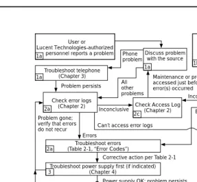
Figure 1-7. Maintenance Strategy
Trouble Reports
System trouble can be reported in two ways:
■ By users
■ By system alarms (permanent errors)
User or Lucent Technologies-authorized
personnel reports a problem
Troubleshoot telephone (Chapter 3) 1a 1a 1a Discuss problem with the source Phone
problem
Check error logs (Chapter 2) 2a
Problem persists Allother problems
Maintenance or programming accessed just before error(s) occurred
Check Access Log (Chapter 2) 2c Inconclusive
Problem gone; verify that errors
do not recur Can’t access error logs
Inconclusive
Check permanent errors
in error logs (Chapter 2) 1b
One or more alarms turn on: Attendant Alarm LED Processor LED Supplemental alert Status display Can’t access error logs Errors 2b
Troubleshoot power supply (Chapter 4) 2b Troubleshoot processor (Chapter 4) 2b Troubleshoot carrier (Chapter 4) 2b
Escalate to NSAC or Lucent
Technologies-authorized dealer
Escalate to NSAC or Lucent Technologies-authorized dealer 9 Problem persists Problem persists Problem persists Problem persists 2a Troubleshoot errors (Table 2-1, “Error Codes”)
Errors
Corrective action per Table 2-1
3 4 5 6 7 8
Troubleshoot power supply first (if indicated) (Chapter 4)
Power supply OK; problem persists
Processor OK; problem persists
Modules OK; problem persists
Carrier OK; problem persists
Trunks OK; problem persists Troubleshoot processor (if indicated)
(Chapter 4) Troubleshoot modules (Chapter 4) Troubleshoot carrier (Chapter 4) Troubleshoot trunks (Chapter 5)
Troubleshoot central office (Chapter 5)
Maintenance and Troubleshooting 555-650-140 June 1997
Introduction
Page 1-22 Maintenance Strategy
Automatic Tests
The system performs ongoing maintenance automatically by running tests that:
■ Monitor the status of equipment.
■ Audit operations consistency.
■ Detect hardware malfunctions.
Without disrupting normal service, the tests check hardware and software that are in service. The system registers any errors it detects in the error logs and, if possible, corrects them automatically.
Alarms
If the automatic tests indicate serious error conditions, the system generates an alarm. Depending on how the system is programmed, the system announces an alarm condition in one of the following ways:
■ An LED for a line or feature button turns on at an operator console or
other designated telephone.
■ The red status LED on the processor module lights.
■ In Release 3.0 and later, the error code/status display on the processor
module displays F if a frigid start, or C if a cold start, occurs. See ‘‘System Restarts’’ for details about frigid start (System Erase) or cold start (Restart).
If a software installation or upgrade is taking place, a blinking character is displayed to indicate the status of the procedure. See ‘‘Forced
Installation/Upgrade of System Software’’ in Chapter 4 for more information.
■ The status display indicates an alarm (on an MLX-20L console or a PC
running SPM), and can be viewed on the Error screen.
MERLIN LEGEND Communications System Release 5.0
Maintenance and Troubleshooting 555-650-140 June 1997Issue 1
Introduction
Page 1-23 Maintenance Strategy
If an LED is programmed to indicate the alarm, the LED stays lit until the error is cleared.
When the system indicates an alarm, check the permanent error log screen.
Clearing Alarms
The system clears alarms automatically when the error condition no longer exists.
To clear an alarm manually, select Drop on the MLX-20L console or !+P on
a PC while viewing the error. See ‘‘Error Logs’’ in Chapter 2 for more information.
System Restarts
Depending on the severity and duration of a problem, you may need to restart the system manually. Some errors cause the system to restart automatically. Every restart causes an error log entry, and each type of restart has its own error code. A cold start (Restart) or frigid start (System Erase) also causes a C
or F to appear on the error code/status display on the processor module. There are three types of system restarts, all of which occur automatically:
■ Warm start (you cannot select this from the Maintenance menu)
■ Cold start (select Restart to do this manually)
■ Frigid start (select System Erase to do this manually)
Warm Start
Maintenance and Troubleshooting 555-650-140 June 1997
Introduction
Page 1-24 Maintenance Strategy
Considerations
■ Power interruptions of less than 100 ms usually do not affect the system.
■ Warm starts may cause telephones without incoming calls to ring.
Cold Start (Restart)
If you need to restart the system, cold start (Restart) is recommended.
Restart drops all calls but saves system programming.
To perform a cold start, select Restart as follows:
Console Procedure Menu→SysProgram→Exit→System→→Yes
PC Procedure →→→→
Considerations
■ A cold start (Restart) occurs automatically after a power interruption of
more than one second.
■ A cold start (Restart) does not blank out the screen on an MLX-20L
telephone until the cold start is completed.
■ A cold start (Restart) can cause extensions with the Extension Status
feature to lose their toll restrictions.
■ For more information on the Restart procedure, see System
Programming.
MERLIN LEGEND Communications System Release 5.0
Maintenance and Troubleshooting 555-650-140 June 1997Issue 1
Introduction
Page 1-25 Maintenance Strategy
Frigid Start (System Erase)
!
CAUTION:
All system programming is erased. When you perform a frigid start (System Erase), all calls are dropped, and the system configuration information is erased. All system memory must be reinitialized, including system programming. Then the entire system must be rebooted.
To perform a frigid start, select System Erase as follows:
Console Procedure Menu→Maintenance→Slot→Dial00→Demand
Test→System Erase (Line 5 of the display, left
button)→System Erase→Yes
PC Procedure →→Type 00→→→→
Considerations
■ System Erase is not displayed on the MLX-20L status display. To select
System Erase, press the left button on Line 5 of the display twice.
■ After a System Erase, the default printer is the PC printer, not the Station
Message Detail Recording (SMDR) printer. If you want on-site printouts from the SMDR printer, make sure you change the option.
■ To change the printer option, see System Programming and
Maintenance (SPM) for information on the Print Opts option on the SPM Main Menu.
For more information on System Erase, see ‘‘Processor Problems’’ in
Maintenance and Troubleshooting 555-650-140 June 1997
Introduction
Page 1-26 Maintenance Strategy
Isolating the Trouble
You can isolate any problem to one of the following areas:
■ Telephone
■ Control unit
■ Central office
NOTE:
If you change the jack assignment of any telephone, be sure to record the extension jack change on Form 2a, System Numbering: Extension Jacks. See Appendix B, ‘‘System Numbering Forms’’, for details.
Check Telephone Problems
If a customer reports telephone problems, use the following steps as a guideline for determining the possible cause. Chapter 3, ‘‘Telephone Problems’’,
discusses telephone problems in more detail.
Discuss the problem with the user who reported the problem.
Run the appropriate test to verify the complaint.
Replace the telephone with one that works properly.
If the problem persists, go to ‘‘Check the Error Logs’’ below.
If the problem persists, replace the telephone wiring.
Check the Error Logs
If a system alarm turns on (see the top-right area of Figure 1-7), begin troubleshooting by checking the permanent errors in the error logs.
MERLIN LEGEND Communications System Release 5.0
Maintenance and Troubleshooting 555-650-140 June 1997Issue 1
Introduction
Page 1-27 Maintenance Strategy
Chapter 2. Also, when you check the error logs, you should refer to Table 2-2, "Error Codes", in Chapter 2 for a detailed description of each problem.
Check the permanent errors.
If errors still exist, check the transient errors.
Check the last 30 errors whenever you want to review the 30 most recently recorded errors—either permanent or transient.
NOTE:
Prior to Release 4.0, the error log displays only the last 10 messages.
Trouble Accessing the Error Logs
If you cannot access the error logs, or if the system is inoperable, use the following steps as a guideline to troubleshoot the system.
Check the power supply LED.
a. Is the power switch turned on?
b. Is the power cord connected to an AC wall outlet that is not controlled by a wall switch?
If the LED is off and you are sure that the power is connected and turned on, see ‘‘Power Supply Problems’’ in Chapter 4.
If you still cannot access the error logs after checking the power supply, see ‘‘Processor Problems’’ in Chapter 4.
If you still cannot access the error logs after checking the processor, see ‘‘Carrier Problems’’ in Chapter 4.
If you still cannot access the error logs, review the “System
Maintenance and Troubleshooting 555-650-140 June 1997
Introduction
Page 1-28 Maintenance Strategy
Check the Access Log
At any time during the maintenance process, you can check the access log for maintenance and system programming. This log indicates the last 20 times that someone accessed maintenance or system programming. If you find that someone accessed maintenance or system programming shortly before the problem originated, that person may be able to help you isolate the trouble by providing additional information on what was done.
Once you receive that information, use any maintenance or system
programming feature that may lead to the root of the problem. See “Access Log
for Maintenance and System Programming” in Chapter 2 for additional
information. See System Programming for information about system
programming and the Inspect function.
Check the Power Supply
If the error logs indicate the power supply as the source of the problem, see
‘‘Power Supply Problems’’ in Chapter 4.
Check the Processor
If the error logs indicate the processor as the source of the problem, use the following as a guideline to check the processor.
■ Back up system programming.
— System programming can be backed up to a floppy disk, using SPM.
— For Release 3.0 and later, system programming can be backed up to a memory card, using SPM or the MLX-20L console. See
Appendix D, ‘‘Backing Up with a Memory Card’’, for more information.
MERLIN LEGEND Communications System Release 5.0
Maintenance and Troubleshooting 555-650-140 June 1997Issue 1
Introduction
Page 1-29 Maintenance Strategy
Check the Modules
If the error logs indicate any modules, see ‘‘Module Problems’’ in Chapter 4.
Check the Control Unit Carrier
Within the control unit, the last possible cause of a problem is the carrier. If the carrier is damaged, it must be replaced. See ‘‘Carrier Problems’’ in Chapter 4
for instructions.
Check the Trunks
Troubleshoot the trunks that are connected to the control unit. See Chapter 5, ‘‘Central Office Problems’’.
Check the Central Office
If the error logs indicate the central office (CO) as the source of the problem, and you have resolved all other possible causes, notify the customer that they should call the central office and ask the central office to check the problem at their end (see Chapter 5, ‘‘Central Office Problems’’):
■ If the problem is in the central office, wait for the CO to fix it. Then
duplicate the problem conditions to ensure that the problem is really fixed.
■ If the problem persists, get the customer to again call the central office
with the problem.
■ If they indicate that the problem is not in the central office, escalate the
problem as described below.
Escalating the Problem
Maintenance and Troubleshooting 555-650-140 June 1997
Introduction
Page 1-30 Unit Loads
See ‘‘System Inventory’’ in Chapter 2, which explains how to access the System Inventory screen. This screen contains information (such as the hardware vintage, software vintage, and ROM ID for each module) that your technical support organization may request.
Unit Loads
A unit load is a measure of power (1.9 watts) used to determine the electrical load that the following components have on each carrier’s power supply:
■ Telephones and adjuncts
■ Direct-Inward Dial (DID) modules
Only the telephones and adjuncts that connect to the analog and digital ports on the control unit require unit load calculation. Do not include any equipment with its own power supply (for example, an answering machine) in the unit load calculation.
Checking Unit Loads
In the event of maintenance or equipment changes, recalculate the unit loads for each carrier where there is a different configuration. Use the worksheet in
Appendix C, ‘‘Unit Load Calculation Worksheet’’.
Generally, if you can distribute the DID modules and telephone modules equally across the carriers, you prevent unnecessary drain on any one carrier.
MERLIN LEGEND Communications System Release 5.0
Maintenance and Troubleshooting 555-650-140 June 1997Issue 1
Introduction
Page 1-31 Unit Loads
Unit Loads for Hybrid/PBX Mode
The power supply (model 391A1) generally supports six modules of any type in a Hybrid/PBX system. However, if both of the following conditions are true, the unit loads on a carrier can exceed the 54-unit (102.6-watts) maximum:
■ All six carrier slots are occupied by MLX telephone or analog multiline
telephone modules.
■ The carrier has more than 45 MLX-20L telephones and/or 34-button
analog multiline telephones installed.
Unit Loads for Key or Behind Switch Mode
In a Key or Behind Switch system with four or fewer modules, no calculation is needed. The power supply (model 391A1) generally supports four modules of any type in Key or Behind Switch mode.
Upgrading the Power supply
The 391A3 power supply has a maximum rating of 75 unit loads. If your system contains a 391A1 or 391A2 power supply module, and the unit loads for that carrier will exceed 54, it is recommended that a 391A3 power supply be installed in the system. Auxiliary Power Units cannot be used with the 391A3 power supply.
!
CAUTION:
Maintenance and Troubleshooting 555-650-140 June 1997
Introduction
Error Logs, Access Logs, and System Inventory
Page 2-1 Error Logs
MERLIN LEGEND Communications System Release 5.0 Maintenance and Troubleshooting
Issue 1 June 1997
MERLIN LEGEND Communications System Release 5.0 Maintenance and Troubleshooting 555-650-140
Issue 1 June 1997
2
2
Error Logs, Access Logs, and System
Inventory
As described in ‘‘Maintenance Strategy’’ in Chapter 1, much of your
troubleshooting relies on the error logs and the access log, for maintenance and system programming. Both of these maintenance features are described here in detail. This chapter also explains how to access the System Inventory screen, which you may need when you escalate problems to your technical support organization.
For information on entering and exiting maintenance functions on a console or a PC running SPM, see Chapter 1, ‘‘Introduction’’.
Error Logs
When an error occurs, the system records it in the error logs, which are stored in battery backed-up RAM. These errors indicate problems that span the entire system, including the control unit, telephones, adjuncts, and network interface.
Transient errors are less serious than permanent errors. However, some transient errors can become permanent if they occur a certain number of times,
as shown in Table 2-1. The Threshold column indicates the number of
Maintenance and Troubleshooting 555-650-140 June 1997
Error Logs, Access Logs, and System Inventory
Page 2-2 Error Logs
Checking the Error Logs
Once you have reviewed the error logs, you should print the error
information.This will help you determine whether your work has resolved each
problem. (Refer to “Summary” below or System Programming for additional
information about printing.)
Summary
Console Procedure Menu→Maintenance→System→Error
Log→Last30 or Permanent or Transient
NOTE:
Prior to Release 4.0, the error log displays only the last 10 messages.
PC Procedure →→→ or or
Table 2-1. Transient/Permanent Error Thresholds
Error
Code Error Description
Transient/Permanent Threshold
7402 LOOP BIT CONTROL NOT SET 4
7403 NO LOOP CURRENT 4
7404 STUCK RINGING 2
8403 NO EXTERNAL RELEASE 2
840B NO LOOP CURRENT 4
840C STUCK RINGING 2
840D INCORRECT FIRMWARE STATE 2
MERLIN LEGEND Communications System Release 5.0
Maintenance and Troubleshooting 555-650-140 June 1997Issue 1
Error Logs, Access Logs, and System Inventory
Page 2-3 Error Logs
Printing from Console Menu→System Programming→Exit→More→
Print→More→More→Error Log
Printing from PC →→U→→U→U→
To check the error logs, follow the steps below.
Console Display/Instructions Additional Information PC
From the Maintenance menu, select the System option.
Select Error Log.
Select an error log option.
Maintenance Make a selection System
Slot Port
Exit
System:
Make a selection
Status Upgrd/Instll Error Log
Inventory Access Log
Exit Enter
System Error Log: If you select Last 30,
Make a selection see ‘‘Checking the Last 30 Errors’’
Last 30 If you select Permanent, see
Permanent ‘‘Checking Permanent Errors’’
Transient If you select Transient,
(most recent alarm) see ‘‘Checking Transient Errors’’
Maintenance and Troubleshooting 555-650-140 June 1997
Error Logs, Access Logs, and System Inventory
Page 2-4 Error Logs
The most recent alarm message stays on the System Error Log screen until it is replaced by another. The screen does not update the most recent alarm while displayed; to see any updates, you need to exit this screen and re-enter.
Checking Permanent Errors
Follow Steps 1 through 3 above for “Checking the Error Logs.” In Step 3, select Permanent.
Console Display/InstructionsAdditional Information PC.
Line 2 provides a brief description of the error code identified on Line 6. For more information on an error code, see Table 2-2.
Line 3 indicates the slot and port where the error was detected. Line 5 indicates the error’s last occurrence.
NOTE:
Depending on which entry you delete, you might clear an alarm. See
‘‘Alarms’’ in Chapter 1 for additional information about alarms.
Checking Transient Errors
Follow Steps 1 through 3 above for “Checking the Error Logs.” In Step 3, select Transient.
Console Display/InstructionsAdditional Information PC.
Permanent Errors: >
xxxxxxxxxxxxxxxxxxxxxx
Slotxx Portxx Countxxx Press the More button to page D
First mm/dd/yy hh:mm through the permanent errors.
Last mm/dd/yy hh:mm
Code xxxx Press the Drop button to delete !0
Exit an error log entry.
Transient Errors: >
xxxxxxxxxxxxxxxxxxxxxx
Slotxx Portxx Countxxx Press the More button to page U
First mm/dd/yy hh:mm through the transient errors.
Last mm/dd/yy hh:mm
Code xxxx Press the Drop button to delete !0
MERLIN LEGEND Communications System Release 5.0
Maintenance and Troubleshooting 555-650-140 June 1997Issue 1
Error Logs, Access Logs, and System Inventory
Page 2-5 Error Logs
Line 2 provides a brief description of the error code identified on Line 6. For more information on an error code, see Table 2-2.
Line 3 indicates the slot and port where the error was detected. Line 5 indicates the error’s last occurrence.
Checking the Last 30 Errors
Follow Steps 1 through 3 above for “Checking the Error Logs.” In Step 3, select Last 30.
Console Display/InstructionsAdditional Information PC.
Line 2 provides a brief description of the error code identified on Line 6. For more information on an error code, see Table 2-2.
Line 3 indicates the slot and port where the error was detected. Line 5 indicates the error’s last occurrence.
NOTE:
You cannot delete an error log entry from this screen.
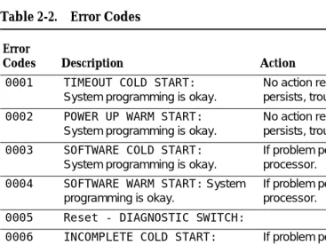
Interpreting Error Codes
Table 2-2 explains how to interpret each error from the error logs.
For additional information on how to use the error logs, read this entire chapter and see ‘‘Maintenance Strategy’’ in Chapter 1.
Last 30 System Errors:>
xxxxxxxxxxxxxxxxxxxxxx
Slotxx Portxx Last mm/dd/yy hh:mm
Code xxxx Press the More button to page
Maintenance and Troubleshooting 555-650-140 June 1997
Error Logs, Access Logs, and System Inventory
Page 2-6 Error Logs
Continued on next page
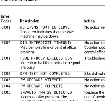
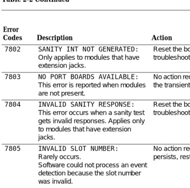
Table 2-2. Error Codes
Error
Codes Description Action
0001 TIMEOUT COLD START:
System programming is okay.
No action required; however, if problem persists, troubleshoot the processor.
0002 POWER UP WARM START:
System programming is okay.
No action required; however, if problem persists, troubleshoot the processor.
0003 SOFTWARE COLD START:
System programming is okay.
If problem persists, troubleshoot the processor.
0004 SOFTWARE WARM START: System programming is okay.
If problem persists, troubleshoot the processor.
0005 Reset - DIAGNOSTIC SWITCH:
0006 INCOMPLETE COLD START:
System was cold-started while a restart was in progress.
If problem persists, troubleshoot the processor.
0007 SANITY TIMEOUT RESET:
Faulty software, module, carrier, or processor sanity timer.
Troubleshoot module and or processor.
0008 MAX RESET COUNT EXCEEDED:
System was cold-started (System Reset) because too many warm starts occurred.
System programming is okay.
MERLIN LEGEND Communications System Release 5.0
Maintenance and Troubleshooting 555-650-140 June 1997Issue 1
Error Logs, Access Logs, and System Inventory
Page 2-7 Error Logs
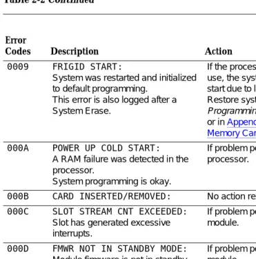
Table 2-2 Continued
Continued on next page Error
Codes Description Action
0009 FRIGID START:
System was restarted and initialized to default programming.
This error is also logged after a System Erase.
If the processor was removed while in use, the system may perform a frigid start due to loss of system programming. Restore system as described in System Programming and Maintenance (SPM), or in Appendix D, ‘‘Backing Up with a
Memory Card’’.
000A POWER UP COLD START:
A RAM failure was detected in the processor.
System programming is okay.
If problem persists, troubleshoot the processor.
000B CARD INSERTED/REMOVED: No action required.
000C SLOT STREAM CNT EXCEEDED:
Slot has generated excessive interrupts.
If problem persists, troubleshoot the module.
000D FMWR NOT IN STANDBY MODE:
Module firmware is not in standby mode.
If problem persists, troubleshoot the module.
000E COMMAND BUFFER FULL: If problem persists, troubleshoot the processor and module.
000F TASK RUNNING TOO LONG: No action required: however, if problem persists, troubleshoot the processor.
0010 INVALID SLOT INTERRUPT:
Cannot determine module responsible for generating the interrupt.
Troubleshoot modules and replace if necessary. If problem persists, troubleshoot the processor.
0011 STACK OVERFLOW:
Processor problem.
Maintenance and Troubleshooting 555-650-140 June 1997
Error Logs, Access Logs, and System Inventory
Page 2-8 Error Logs
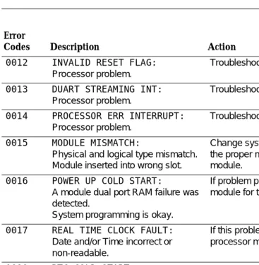
Table 2-2 Continued
Continued on next page Error
Codes Description Action
0012 INVALID RESET FLAG:
Processor problem.
Troubleshoot the processor.
0013 DUART STREAMING INT:
Processor problem.
Troubleshoot the processor.
0014 PROCESSOR ERR INTERRUPT:
Processor problem.
Troubleshoot the processor.
0015 MODULE MISMATCH:
Physical and logical type mismatch. Module inserted into wrong slot.
Change system programming to reflect the proper module or install the proper module.
0016 POWER UP COLD START:
A module dual port RAM failure was detected.
System programming is okay.
If problem persists, troubleshoot the module for the slot indicated.
0017 REAL TIME CLOCK FAULT:
Date and/or Time incorrect or non-readable.
If this problem persists, replace the processor module.
0018 RTC COLD START:
This error is not displayed.
0019 RESET TIME & DATE:
The system performs a cold start because the real time clock chip is not working correctly.
If this problem persists, replace the processor module.
0401 ABK CARD NOT INSERTED:
A PCMCIA memory card for Translation is not inserted.
Insert a Translation card or a card that has not been formatted.
0