'ZRTGUU
"
.
98:
5&5."4QWVGT1$TKFIG"
2CTV
"
0WODGTU
"34253;4
.
3"
&QEWOGPV
"
0WODGT
"834253;4
.
3/42
#
DMS-100 is a trademark of Northern Telecom, Inc.
Ethernet is a trademark of Digital Equipment Corporation, Intel Cor-poration, and Xerox Corporation.
Expert ISDN (patent number 5,715,241) is a trademark of ADTRAN, Inc.
Macintosh is a registered trademark of Apple Computer, Inc. Novell, NetWare, and Internetwork Packet Exchange (IPX) are regis-tered trademarks of Novell, Inc.
Windows is a registered trademark of Microsoft Corporation. 5ESS is a registered trademark of LUCENT.
901 Explorer Boulevard P.O. Box 140000 Huntsville, AL 35814-4000
(256) 963-8000
© 1999 ADTRAN, Inc. All Rights Reserved.
1. If this equipment causes harm to the telephone network, the telephone company may temporarily discontinue ser-vice. If possible, advance notification is given; otherwise, notification is given as soon as possible. The telephone company will advise the customer of the right to file a complaint with the FCC.
2. The telephone company may make changes in its facili-ties, equipment, operations, or procedures that could affect the proper operation of this equipment; advance notification and the opportunity to maintain uninter-rupted service are given.
3. If experiencing difficulty with this equipment, please con-tact ADTRAN (see inside back cover) for repair and war-ranty information. The telephone company may require this equipment to be disconnected from the network until the problem is corrected or until it is certain the equip-ment is not malfunctioning.
4. This unit contains no user serviceable parts.
This equipment has been tested and found to comply with the limits for a Class B digital device, pursuant to Part 15 of the FCC Rules. These limits are designed to provide reasonable protection against harmful interference when the equipment is operated in a commer-cial environment. This equipment generates, uses, and can radiate radio frequency energy and, if not installed and used in accordance with the instruction manual, may cause harmful interference to radio or TV reception. The user is encouraged to try to correct the interfer-ence by one or more of the following measures:
1. Reorient or relocate the receiving antenna.
2. Increase the separation between the equipment and receiver.
3. Connect the equipment into an outlet on a circuit different from that to which the receiver is connected.
4. Consult the dealer or an experienced radio/TV technician for help.
READINESS DISCLOSURE
ADTRAN has established a Year 2000 program to ensure that our products and operations will correctly function in the new millen-nium. ADTRAN warrants that all products meet Year 2000 specifica-tions regardless or model or revision. Information about ADTRAN’s Year 2000 compliance program is available at the following:
Web Site www.adtran.com
Product Matrix www.adtran.com/Y2Kfax.html
Faxback Document Line (256) 963-8200
Y2K plans and product certifications are listed in the matrix
Y2K Project Line (256) 963-2200
This digital apparatus does not exceed the Class B limits for radio noise emissions from digital apparatus as set out in the interference-causing equipment standard entitled "Digital Apparatus," ICES-003 of the Department of Communications.
Cet appareil nuerique respecte les limites de bruits radioelectriques applicables aux appareils numeriques de Class B prescrites dans la norme sur le materiel brouilleur: "Appareils Numeriques," NMB-003 edictee par le ministre des Communications.
CANADIAN EQUIPMENT LIMITATIONS
Notice: The Canadian Industry and Science Canada label identifies certified equipment. This certification means that the equipment meets certain telecommunications network protective, operational, and safety requirements. The Department does not guarantee the equipment will operate to the user’s satisfaction.
Before installing this equipment, ensure that it is permissible to be connected to the facilities of the local telecommunications company. The equipment must also be installed using an acceptable method of connection. In some cases, the company’s inside wiring associated with a single-line individual service may be extended by means of a certified connector assembly (telephone extension cord). Compliance with the above conditions may not prevent degradation of service in some situations.
Repairs to certified equipment should be made by an authorized Ca-nadian maintenance facility designated by the supplier. Any repairs or alterations made by the user to this equipment, or equipment mal-functions, may give the telecommunications company cause to re-quest the user to disconnect the equipment.
Users should ensure for their own protection that the electrical ground connections of the power utility, telephone lines, and internal metallic water pipe system, if present, are connected together. This precaution may be particularly important in rural areas.
When using your telephone equipment, basic safety precautions should always be followed to reduce the risk of fire, electric shock and injury to persons. The precautions are listed below.
1. Do not use this product near water (for example, near a bath tub, wash bowl, kitchen sink or laundry tub, in a wet basement or near a swimming pool).
2. Avoid using a telephone (other than a cordless type) dur-ing an electrical storm. There may be a remote risk of elec-tric shock from lightning.
3. Do not use the telephone to report a gas leak in the vicinity of the leak.
4. Use only the power cord, power supply, and/or batteries indicated in the manual. Do not dispose of batteries in a fire. They may explode. Check local codes for any special disposal instructions.
Table of Contents
Appendix B Log Messages . . . .B-1
Appendix C SNMP . . . .C-1
Appendix D Connector Pinouts . . . D-1
Appendix E Terminal Mode Commands . . . E-1
Acronyms . . . .Acronyms-1
Glossary . . . Glossary-1
List of Figures
Figure 1-1. Express L768 . . . 1-2 Figure 1-2. Single User to Corporate LAN . . . 1-3 Figure 1-3. Frame Relay Connectivity to ADTRAN
List of Tables
SETTING UP THE SDSL LINE
The Express L768 works over leased or “dry” copper provided by the local telephone company. SDSL is actually one loop or half rate HDSL. See Specifications on page 4-1 for specifications on maximum distance. If the Express L768 is to be used in a back-to-back configuration, the line mode must be different for each unit.
1. Connect a VT 100 async terminal, or personal computer with a terminal emulator running 9600 N-8-1, to the MAINTENANCE port.
2. Hold down the Control key and press R; then press Enter to dis-play the top menu.
3. Using the arrow keys and Enter key to navigate the menu, go to the Configuration/WAN/HDSL menu. Enter the line mode as HTU-C or HTU-R. Each end of an SDSL circuit must be of oppo-site mode.
4. Set the rate of transfer that will be used. Both devices must be set at the same rate.
5. Use the left arrow key or the Escape key to go back up the menu tree. When asked to save HDSL parameters, type y.
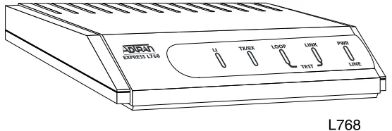
Express L768
SDSL OVERVIEW
Symmetrical Digital Subscriber Loop (SDSL) is high bit rate Digital Subscriber Loop (HDSL) running at half its full rate, using only two wires instead of four. HDSL is rapidly becoming the service providers’ technology of choice for the deployment of T1 services: according to recent estimates, over 60% of today’s T1 installations use HDSL tech-nology. Instead of traditional methods requiring multiple T1 repeat-ers, HDSL allows the telephone companies to quickly deploy a T1 circuit over Carrier Serving Area (CSA) loops (9,000 feet on 26 AWG wire or 12,000 feet on 24 AWG wire) without loop conditioning or re-peater installation. SDSL offers higher bandwidth, using the same two wires that are traditionally used for DDS and ISDN technology. ADTRAN provides a full line of HDSL and SDSL products that are the price/performance leaders in the industry.
THE EXPRESS L768
port can connect to any asynchronous terminal emulating a VT 100 terminal for configuration.
Figure 1-1. Express L768
Applications
Single User to Corporate LAN (Figure 1-2)
• Telecommuter/Home Office Access to the corporate LAN • Single device access
• User Datagram Protocol (UDP) broadcasts are “relayed” to corporate LAN.
• Client device can obtain the Internet Protocol (IP) address dynamically using Dynamic Host Configuration Protocol (DHCP).
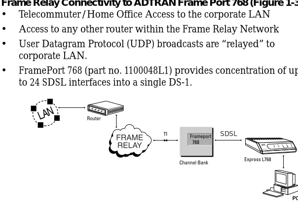
Figure 1-2. Single User to Corporate LAN
Frame Relay Connectivity to ADTRAN Frame Port 768 (Figure 1-3) • Telecommuter/Home Office Access to the corporate LAN • Access to any other router within the Frame Relay Network • User Datagram Protocol (UDP) broadcasts are “relayed” to
corporate LAN.
• FramePort 768 (part no. 1100048L1) provides concentration of up to 24 SDSL interfaces into a single DS-1.
9
Small Office - Home Office (SOHO) to Corporate LAN (Figure 1-4) • Connects the small office or home office to the corporate LAN • Routes IP and Internet Packet Exchange (IPX) traffic from
multiple devices to the corporate LAN • Bridges all non-routed traffic (e.g., AppleTalk) • Low cost alternative to buying a high-end router
• Compatible with popular central site LAN access devices
Figure 1-4. SOHO to Corporate LAN
The Express L768 provides the following basic functions: 1. LAN Bridge: Bridging provides a point-to-point connection
between two LANs. The bridge learning function scans the source and destination media access control (MAC) addresses of all packets on its local LAN and determines which packets should be transmitted over the SDSL link. Applications include connectivity between single user or small offices to corporate LANs. The Express L768 uses the Spanning Tree Algorithm (IEEE 802.1d-ISO/IEC10038), which provides a loop-free topology and redundancy.
2. IP Router: The Express L768 can function as an IP router using the Routing Information Protocol (RIP) for advertising and learn-ing routes among other routers. Static routes may also be entered into the routing table.
3. IPX Router: IPX routers and services can be exchanged between the Express L768 and other devices using RIP and Service Adver-tising Protocol (SAP). Watch dog serialization filtering and spoof-ing can permit the ISDN to be idle durspoof-ing no application traffic periods.
4. Network Address Translation (NAT): Single networks can con-nect to the Internet with this function. The Express L768 trans-lates outgoing IP packets over the SDSL to the IP router at the Internet Service Provider. Many popular Internet applications are supported.
Routing and Bridging with the Express L768
The Express L768 is a Router and Transparent Learning Bridge. Its fea-tures can be easily configured and used once several basic concepts are understood.
Factory Default
The Express L768 comes from the factory configured for MAC Bridg-ing with no filters or connection information defined. An IP address of 10.0.0.1 with a network mask of 255.255.255.0 is preloaded. The facto-ry default layer two configuration is Auto Detect, which automatically detects PPP or Frame Relay.
Bridging
In Bridge Mode, the Express L768 can be used to connect two LAN segments. In this mode, all protocols are supported because they are transported across the SDSL link at the MAC layer. The Spanning Tree Algorithm can be used to guarantee a loop-free topology. MAC ad-dresses are “learned” by each Express L768 to prevent non-WAN packets from being bridged.
IP Routing
IPX Routing
Network routes and services are learned and advertised using Nov-ell’s RIP and SAP.
Concurrent Routing And Bridging
The Express L768 can route IP and IPX as well as bridge non-IP/IPX packets simultaneously. The PPP profile will by default negotiate PPP network protocols to support the transmission and reception of IP, IPX, and Bridge packets. If the PPP peer does not accept a protocol, the Express L768 will fall back to any combination of routing and bridg-ing.
Network Address Translation Mode
NAT is a special mode of operation in which the Express L768 obtains a dynamically assigned IP address from the peer router (typically an Internet Service Provider). This allows a network of computers to ap-pear as a single IP address.
Front Panel
Figure 1-5 shows the front panel of the Express L768. The indicators are divided into LAN functions, WAN functions, and Test functions.
Figure 1-5. Express L768 Front Panel Indicators
Rear Panel
The Express L768 has one RJ-45 jack, labeled HDSL, on the rear panel for network connection (see Figure 1-6). There are two sets of switches on the back panel. The TO HUB/TO NIC switch allows the Express L768 to connect directly to a Network Interface Card (NIC) or a HUB without the need for special cabling.
TX/RX Flashes when transmitting and receiving data on the 10BaseT connector.
LI Link integrity. Illuminates when there is a good connection between the Express L768 and the Hub/NIC card.
LOOP Flashes when the SDSL link (pins 4 and 5 on RJ-45) is not in sync. Solid when in sync.
The OFF/ON switch block is for factory default and firmware down-loading. With switch 1 in the up or OFF position, the Express L768 will immediately go into a download mode when power is enabled. Switch 1 must be in the down or ON position in order to boot up nor-mally. Switch 2 in the up or OFF position will force the entire config-uration to be factory defaulted.
The Express L768 transfers data up to 768 kbps over a two-wire facil-ity. This type of service is a permanent connection between endpoints or between the unit and the Frame Relay cloud. It is sometimes re-ferred to as a leased connection, a dedicated connection, a “nailed-up” connection, or a private circuit. Leased connection or leased line is used in this manual to represent these types of services.
Figure 1-6. Express L768 Rear Panel
Configuration
The Express L768 is configured using a menu-based interface. This interface can be accessed via the maintenance port using any asyn-chronous VT 100 terminal or personal computer running a terminal emulation program, or via IP using a Telnet client program or web browser. To use the Telnet interface or web browser, the Express L768 must first have an IP address programmed into it via the maintenance
The Telnet and web browser configuration can also be protected using the same authentication methods. Each menu item in the Express L768 has a security level associated with it. A Telnet session is as-signed a privilege level which determines which menu items are ac-cessible to the Telnet client. See Security Levels on page 3-7 for more information on menu security levels.
Filters can be defined to prevent certain addresses or protocols from being transferred from LAN-to-WAN, LAN, or WAN-to-WAN.
After unpacking the unit, immediately inspect it for possible shipping damage. If damage is discovered, file a claim immediately with the shipping carrier; then contact the ADTRAN Customer and Product Service (CAPS) department (see inside back cover for information).
SDSL NETWORK CONNECTION
T1 Overview
The T1 digital communications link has been used by telephone com-panies (telcos) for transmitting voice since the early sixties. The D4 channel bank is a T1 digital carrier system that was introduced in the mid-seventies and is still widely used by telcos. Communication de-mands of businesses continued to grow to the point that the telcos be-gan offering T1 service directly to the public. D4 channel banks bebe-gan to be used for T1 in corporate network topographies for voice. The ad-vances in computer development also created a demand for T1 data communication which now is a large part of the T1 traffic.
SDSL Overview
A new technology has been developed for the telcos for delivery of T1 service. The technology is known as high-bit-rate digital subscriber line (HDSL). HDSL employs a 2B1Q modulation technique across the same types of pairs traditionally encountered with metallic T1 deliv-ery systems. HDSL satisfies the telco distance requirements without the use of repeaters.
Symmetric Digital Subscriber Loop (SDSL) is HDSL using only one pair. This provides a maximum of 768 kbits/sec, which is half the rate of HDSL.
LOCAL AREA NETWORK CONNECTION
The Express L768 has a 10BaseT connector that provides half-duplex 10 Mbps operation over a four-wire twisted pair. Place the switch in the TO HUB position when connecting to a 10BaseT concentrator or Hub. Place the switch in the TO NIC position when connecting direct-ly to a computer’s 10BaseT network interface card.
and Structure
TERMINAL MENU STRUCTURE
The Express L768 uses a multilevel menu structure containing both menu items and data fields. All menu operations and data display in the terminal menu window. The Express L768 is shipped in the Facto-ry Default configuration. Connect any VT 100 or VT 220 type terminal emulator to the maintenance port. The default rate is 9600 baud 8-N-1. The terminal emulator can flow the Express L768 off using software flow control. Hardware flow control is not used.
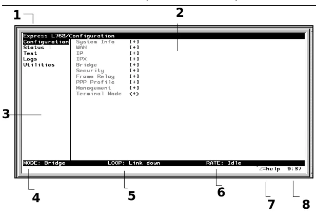
The opening menu (the Main menu, or top-level menu) is the access point to all other operations. Each Main menu item has several func-tions and submenus to identify and access specific parameters. Figure 3-1 on page 3-3 shows the top-level terminal menu.
The Main menu contains the following options.
>
CONFIGURATION
The Configuration menu provides options to set up the operational configuration for the Express L768. See the section Configuration Menu on page 3-8 for detailed information on the available options.
>
STATUS
The Status menu provides options to review and monitor the status of the Express L768 system. See the section Status Menu on page 3-61 for detailed information on the available options.
>
TEST
The Test menu can be used for performing diagnostic testing of the Express L768. See the section Test Menu on page 3-72 for detailed in-formation on the tests available.
>
LOGS
The Logs menu can be used for viewing the operational logs for the Express L768. See the section Logs Menu on page 3-73 for detailed in-formation on the available options.
>
UTILITIES
1 Menu Path Describes the current position in the terminal menu structure.
2 Right Pane Lists available submenus. Additional sub-menus available through this pane are indicat-ed by the [+] and [DATA] symbols.
3 Left Pane Lists available menus.
4 Mode Describes current operating mode. 5 Loop Status Displays current status of HDSL line. 6 Rate Status Displays current rate of connection. 7 Navigation
Help
Displays list of characters you can use to navi-gate the terminal menus (press Control-Z). 8 System Time Displays the current time. See Date/Time on
page 3-9 for details on setting the time.
3
4
5
6
7
8
NAVIGATING THE TERMINAL MENUS
The following sections provide information on how to navigate through the terminal menus.
General Layout
When you first start a terminal mode session, the screen shown in Fig-ure 3-1 on page 3-3 displays. The screen is divided into left and right panes. The left pane shows the current list of submenus, while the right pane shows the contents of a selected submenu.
Menu Path
The top line of the display shows this session’s current position (path) in the menu tree. Figure 3-1 on page 3-3 shows the top menu level with the cursor on the Configuration submenu, so the path display shows Express 768/Configuration.
Moving Around
Press Tab or the right arrow key to move the cursor from the left pane to the right pane. Press Tabor the left arrow key to move the cursor from the right pane back to the left pane. Use the up and down arrows to move around within each pane. Press Enter to activate a menu. Press the left arrow key or the Escape key to go back up the menu. The following options display throughout the menus.
Submenus [+] or [DATA]
Menus that display [+] or [DATA] indicate that more items are avail-able when selected.
Activation Field <+>
Editable Data Field
A highlighted menu item indicates that you can enter data in that field.
Read-Only Field
An underlined field is a display field that contains read-only informa-tion.
Navigation with the Keyboard
You can use different keystrokes to navigate through the terminal menu. Press Control-Z to activate a pop-up screen with the available keystrokes. The following section provides a list of the available key-strokes and the results:
General Navigation
H Returns to the home screen.
J Jumps between two menu items. Press J while on a menu item of interest, and you will jump back to the main screen. Go to another menu item of interest, Press
J, and you will jump back to the screen that was displayed the first time you pressed J. Press J anytime you want to jump between these items.
Arrow Keys Selects items and moves between the left and right
panes. The left arrow key allows you to go back up the menu.
Session Management
Control-L Logs out of the session.
Control-S Invalidates the password entry and returns to the login
screen. The Password prompt will display.
Control-R Refreshes the screen. To save time, only the portion of the
screen that has changed is refreshed. This option should be necessary only if the display picks up incorrect characters.
Configuration
F Restores factory default settings. This setting restores the factory
defaults based on the location of the cursor. Entire submenus can be factory defaulted.
C Copies selected items to the clipboard. The amount of
information you can copy depends on the cursor location when you press C. For example, if the cursor is over an editable field, only that item is copied. If the cursor is over the index number of a list, then all of the items in the row of the list are copied. For example, if the cursor is over the Num field in the Frame Relay Mapping screen, all of the information associated with the Map entry is copied.
P Pastes the item stored in the clipboard, if the information in
compatible. You must confirm all pastes except those to a single editable field.
> For certain types of fields, when you paste information into the
field, the value increments by 1.
< For certain types of fields, when you paste information into the
field, the value decrements by 1.
I Inserts a new item in a list. For example, add a new item to the
Connection List by pressing I while the cursor is over the index number.
D Deletes a list item. For example, delete an item from the
Security Levels
Each menu item on the configuration screens has an associated secu-rity level. The secusecu-rity level ranges from 0 (highest secusecu-rity level) to 5 (lowest security level). This level determines whether a Telnet session can access that menu item. The Telnet session is assigned a security level set by the user. Passwords can only be accessed as security level 0. The maintenance port is always at security level 0.
The security levels are assigned as follows: Level
0 Access all parameters including passwords 1 Access all parameters except passwords 2 Access all parameters except passwords and
authentication methods
3 Access all parameters except passwords, authentication methods, and HDSL parameters
>
CONFIGURATION MENU
» System Info
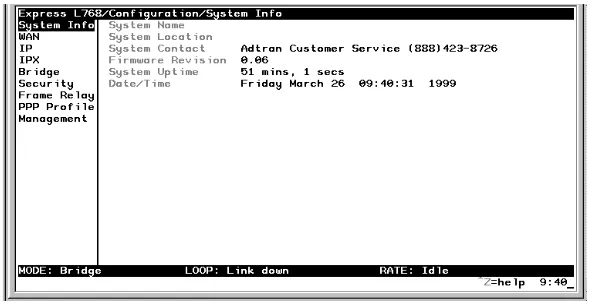
The System Info menu provides basic information about the unit and displays data fields for editing information. Figure 3-2 displays the submenus available under this menu item.
Figure 3-2. Configuration/System Info Screen
»» System Name
Write security: 3; Read security: 5
Provides a user-configurable text string for the name of the Express L768. This name can help distinguish between different installations. You can enter up to 31 alpha-numeric characters in this field, includ-ing spaces and special characters (such as an under bar). The system name is also used for PPP authentication and IPX service name. »» System Location
Write security: 3; Read security: 5
can enter up to 31 alpha-numeric characters in this field, including spaces and special characters (such as an under bar).
»» System Contact
Write security: 3; Read security: 5
Provides a user-configurable text string for the contact name. This field can contain a name, phone number, or e-mail address of a person responsible for the Express L768. You can enter up to 31 alpha-numer-ic characters in this field, including spaces and special characters (such as an under bar).
»» Firmware Revision Read security: 5
Displays the current firmware revision level of the Express L768. This field is a read-only field.
»» System Uptime Read security: 5
Displays the length of time the Express L768 has been running since power up or reset. This field is a read-only field.
»» Date/Time
Write security: 3; Read security: 5
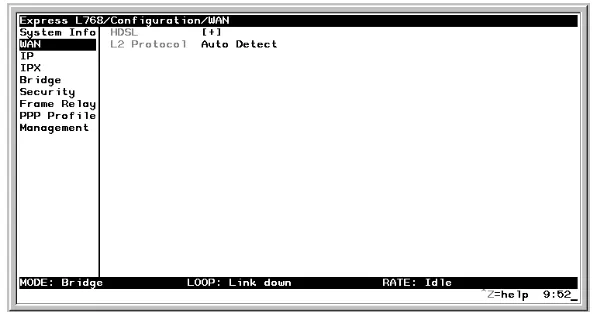
» Configuration/WAN
The WAN menu is used to set up the ISDN parameters for the Express L768. Figure 3-3 shows the WAN menu.
Figure 3-3. Configuration/WAN Screen
»» WAN/HDSL
Write security: 2; Read security: 5 Selects the mode the HDSL line is in.
HDSL/Mode
Write security: 2; Read security: 5
HDSL/Channel Rate
Write security: 2; Read security: 5
Determines the rate at which data is transferred over the HDSL link. Possible rates are 128K, 192K, 256K, 320K, 384K, 448K, 512K, 576K, 640K, 704K, 768K, and AUTO. AUTO is selected if the rate is to be de-termined automatically.
HDSL/NEBEs Read security: 5
This contains the number of Near-End-Block-Errors (NEBEs) that have been detected by the Express L768’s HDSL circuitry. Continuous errors can indicate a line problem, but a burst at one time is normal.
HDSL/FEBEs Read security: 5
This contains the number of Far-End-Block-Errors (FEBEs) that have been detected by the HDSL circuitry on the other end of the link. Con-tinuous errors can indicate a line problem, but a burst at one time is normal.
»» WAN/L2 Protocol
Write security: 3, Read security: 5
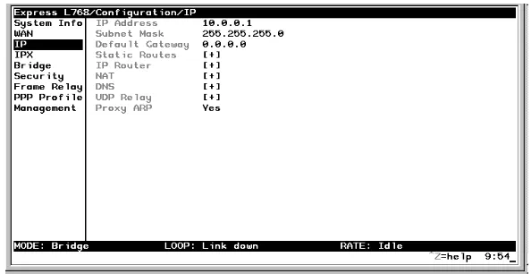
Configura-» Configuration/IP
The IP menu is used to set up the IP parameters for the Express L768. Any general IP-related configuration item is under this menu. Figure 3-4 shows the IP menu.
Figure 3-4. Configuration/IP Screen
»» IP/IP Address
Write security: 2; Read security: 5
The IP address assigned to the Express L768’s Ethernet port is set here. This address must be unique within the network. Factory default is 10.0.0.1.
»» IP/Subnet Mask
Write security: 2; Read security: 5
»» IP/Default Gateway
Write security: 3; Read security: 5
The default gateway is used by the Express L768 for sending IP pack-ets whose destination address is not found in the route table. If this address is all zeros, then the first WAN connection becomes the de-fault gateway.
»» IP/Static Routes
Static Routes can be inserted under this menu.
Static Routes/Active
Write security: 4; Read security: 5
Adds this static route entry to the IP routing table when set to Yes (def) and removes it (if it was previously added) if set to No.
Static Routes/IP Address Write security: 4; Read security: 5
This is the IP address of the host or network address of the device be-ing routed to.
Static Routes/Subnet Mask Write security: 4; Read security: 5
This mask determines the bits in the previous IP address that are used. If this is to be a host route, it must be set to all ones (255.255.255.255).
Static Routes/Gateway
Static Routes/Private
Write security: 4; Read security: 5
When set to No, the Express L768 will advertise this static route using RIP. Otherwise, setting to Yes means that the route is kept private. »» IP/IP Router
The IP router is configured under this menu as follows.
IP Router/Mode
Write security: 3; Read security: 5
When this option is set to On (def), the Express L768 will advertise and listen to routes from other IP routers. If Off, the route table is still used but only static routes are used for routing IP packets and only the Ethernet port is used. IP packets can be sent over the WAN, but only when bridged.
IP/RIP
Write security: 3; Read security: 5
The Routing Information Protocol (RIP) is supported by the Express L768. The following parameters are required for setting up the mode on the Ethernet port:
RIP/Mode
Write security: 3; Read security: 5 This option turns RIP On (def) or Off RIP/Protocol
RIP/Method
Write security: 3; Read security: 5
RIP/Direction
Write security: 3; Read security: 5
RIP/V2 Secret
Write security: 0; Read security: 0
This is a text string used to authenticate advertised routes. »» IP/NAT
The Network Address Translation general parameters are set up un-der this menu.
Split Horizon Only routes not learned on the Ethernet port are advertised.
Poison Reverse (def)
All routes are advertised, including routes learned from the Ethernet port. These routes are poisoned.
None All routes are advertised, including routes learned from the Ethernet port. No attempt is made to poison these routes.
Tx and Rx (def) RIP advertisements are transmitted and lis-tened to on the Ethernet port.
Tx only RIP advertisements are transmitted and not listened to.
NAT/DHCP Renewal Time Write security: 3; Read security: 5
This is the number of hours that the DHCP server should allow the de-vice before it is required to send a new DHCP request. The default is 15 hours, and 0 represents an infinite lease.
NAT/Web Server
Write security: 3; Read security: 5
This is the IP address of a web server on the Ethernet network. When an active NAT connection is made to the Internet, any HTTP, FTP, or SMTP server requests from the WAN are translated and sent to this web server. Normally, communication across NAT must be initiated from the LAN side of the Express L768. Web Server allows a single machine on the NAT side to be accessed from the Internet side of NAT. This provides outside access to a web server, mail, or ftp server.
NAT/Default IP
This is the IP address used by the Express L768 for Network Address Translation when nothing is assigned during the PPP negotiation when PPP mode is active or when nothing is specified in the DLCI Mapping’s Link IP Address.
»» IP/DNS
DNS/Domain Name
Write security: 3; Read security: 5
This is a text string used to represent the domain name used by the Ex-press L768.
DNS/Server 1
Write security: 3; Read security: 5
This is the IP address for the primary DNS device. It is the first server that domain name requests are sent.
DNS/Server 2
Write security: 3; Read security: 5
This is the IP address for the secondary DNS device. It is used as a back-up in case the primary address does not respond to the request. »» IP/UDP Relay
The Express L768 can be configured as a relay agent for UDP broad-cast packets. Normally, a router will not forward UDP broadbroad-cast packets. However, many network applications use UDP broadcasts to configure addresses, host names, and other information. If hosts using these protocols are not on the same network segment as the servers providing the information, the client programs will not receive a re-sponse without enabling the UDP relay agent.
UDP Relay/Mode
Write security: 3; Read security: 5
UDP Relay List/Relay Address Write security: 3; Read security: 5
This is the IP address of the server that will receive the relay packet. UDP Relay List/UDP Port Type
Write security: 3; Read security: 5
UDP Relay List/UDP Ports 1, 2, and 3 Write security: 3; Read security: 5
UDP Port 1, UDP Port 2, and UDP Port 3 are used for specifying UDP ports to be relayed. These fields only apply when UDP Port Type is set to Specified.
»» IP/Proxy ARP
Write security: 4; Read security: 5
This feature allows the network portion of a group of addresses to be shared among several physical network segments. The ARP protocol itself provides a way for devices to create a mapping between physical (i.e., Ethernet) addresses and logical IP addresses. Proxy ARP makes use of this mapping feature by instructing a router to answer ARP re-quests as a “proxy” for the IP addresses behind one of its ports. The device which sent the ARP request will then correctly assume that it can reach the requested IP address by sending packets to the physical address that was returned to it. This technique effectively hides the fact that a network has been (further) subnetted. If this option is set to Yes (def), when an ARP request is received on the Ethernet port the address is looked up in the IP routing table. If the forwarding port is not on the Ethernet port and the route is not the default route, the
Ex-Standard (def)
The following standard UDP protocols are relayed when set: DHCP, TFTP, DNS, NTP (Network Time Protocol, port 123). NBNS (NetBIOS Name Server, port 137), NBDG (NetBIOS Datagram, port 138), and BootP.
set to No, the Express L768 will only respond to ARP requests received for its own IP address.
» Configuration/IPX
The IPX menu is used to set up the IPX parameters for the Express L768. Any general IPX-related configuration item can be found under this menu. Figure 3-5 shows the IPX menu.
Figure 3-5. Configuration/IPX Screen
»» IPX/Mode
Write security: 2; Read security: 5
»» IPX/Frame Type
Write security: 2; Read security: 5
The Express L768 supports all four defined IPX frame types. The pos-sible frame types are: Ether Type II (def), Ether 802.3 (Raw), Ether 802.2, or Ether SNAP (802.2 SNAP). Only one frame type can be used at one time.
»» IPX/Seed Status
Write security: 2; Read security: 5
The seed status defines what the Express L768 is to do with the net-work information on the selected frame type during startup. There are three possible seeding selections specified:
Seed The Express L768 will listen for an IPX network number being sent by another router (including Novell software routers residing on servers) on the Ethernet segment connected to this port and use this number if it exists. If it does not discov-er a numbdiscov-er in use, the Express L768 will use the configured IPX network number for the Ether-net segment.
Non-Seed (def)
The Express L768 will listen for an IPX network number being sent by another router (including Novell software routers residing on servers) on the Ethernet segment connected to this port and use this number if it exists. If it does not discov-er a numbdiscov-er in use, the Express L768 will wait indefinitely until a number is sent by another router on the Ethernet segment.
Auto-Seed
»» IPX/RIP Timer
Write security: 3; Read security: 5
This value specifies how often the Express L768 sends out IPX RIP packets on the network segment attached to the Ethernet port. The RIP packets sent contain routing information about the networks for which this Express L768 is responsible. The default value is 60 sec-onds.
»» IPX/SAP Timer
Write security: 3; Read security: 5
This value specifies how often the Express L768 sends out IPX SAP (Service Access Protocol) packets on the network segment attached to the Ethernet port. The SAP packets sent contain information about the services (such as servers, printers, etc.) for which this Express L768 is responsible. The default value is 60 seconds.
» Configuration/Bridge
Figure 3-6. Configuration/Bridge Screen
»» Bridge/Mode
Write security: 2; Read security: 5
When this option is set to On (def), the Express L768 bridge function will be enabled. Setting it to Off will disable all bridge functionality. »» Bridge/WAN IP Bridge
When IP routing is active, the Express L768 will allow another WAN device to bridge IP packets to it using PPP BCP. Normally, two IP routers would negotiate PPP IPCP to exchange IP packets. However, if a device can only support PPP BCP, IP packets are encapsulated by the device as bridge packets. The Express L768 can treat the WAN IP Bridge as a virtual Ethernet port connected only to a WAN device which has negotiated PPP BCP. This menu allows the IP parameters for this virtual Ethernet to be set up.
WAN IP Bridge/Network
Write security: 2; Read security: 5
WAN IP Bridge/Netmask Write security: 2; Read security: 5
This is the network mask to be applied to the virtual Ethernet port.
WAN IP Bridge/Triggered Write security: 2; Read security: 5
When set to Yes, only IP RIP updates are sent when the routing table has changed. When set to No (def), updates are sent periodically.
WAN IP Bridge/Proxy ARP
If this option is set to Yes (def), the Express L768 will proxy ARP on the bridge IP port. See the section IP/Proxy ARP on page 3-18 for an ex-planation of the proxy ARP function.
»» Bridge/WAN IPX Bridge
When IPX routing is active, the Express L768 will allow another WAN device to bridge IPX packets to it using PPP BCP. Normally, two IPX routers would negotiate PPP IPXCP to exchange IPX packets. How-ever, if a device can only support PPP BCP, IPX packets are encapsu-lated by the device as bridge packets. The Express L768 can treat the WAN IPX Bridge as a virtual Ethernet port connected only to a WAN device which has negotiated PPP BCP. This menu allows the IPX pa-rameters for this virtual Ethernet to be set up.
WAN IPX Bridge/Frame Type Write security: 2; Read security: 5
This is the frame type used for the virtual Ethernet port. See IPX/ Frame Type on page 3-20 for an explanation of the IPX frame type.
WAN IPX Bridge/Seed Status Write security: 2; Read security: 5
This is the seed status used for the virtual Ethernet port. See IPX/Seed Status on page 3-20 menu for an explanation of the IPX seed status.
WAN IPX Bridge/Triggered Write security: 2; Read security: 5
When set to Yes, only IPX RIP and SAP updates are sent when the routing or service table has changed. When set to No (def), updates are sent periodically.
»» Bridge/Spanning Tree
The Spanning Tree Algorithm and Protocol ensures a loop-free topol-ogy and provides redundancy. The protocol parameters can be spe-cifically tuned from their defaults, though most applications require no adjustment.
Spanning Tree/Mode
Write security: 2; Read security: 5
When the mode is set to On, the Express L768 will participate in the Spanning Tree protocol between other bridges. When Off (def), all bridge ports remain permanently open for forwarding.
Spanning Tree/Priority
Write security: 2; Read security: 5
This assigns a priority to the Express L768 that permits the relative pri-ority of multiple bridges to be managed. The range is 0 to 65535 with a default of 32768.
Spanning Tree/Maximum Age Write security: 2; Read security: 5
This is the timeout value used by the Express L768 to test against the root device. The value is in one-tenth seconds with a range between 60 (6.0 seconds) and 400 (40.0 seconds). The default is 200 (20.0 sec-onds).
Spanning Tree/Hello Time Write security: 2; Read security: 5
This is the time between the generation of configuration BPDUs (Bridging Protocol Data Units) by the root bridge. The value is in one-tenth seconds with a range between 10 (1.0 second) and 100 (10.0 sec-onds). The default is 20 (2.0 secsec-onds).
Spanning Tree/Forward Delay Write security: 2; Read security: 5
This is the time spent in the listening and learning state while moving from the blocking state to the forwarding state. The value is in one-tenth seconds with a range between 40 (4.0 seconds) and 300 (30.0 sec-onds). The default is 150 (15.0 secsec-onds).
LAN Port/Active
Write security: 2; Read security: 5
The Ethernet port can be disabled when set to No. In this mode, no bridge traffic will be forwarded in or out. Setting to Yes (def) allows the port to participate in the spanning tree topology.
LAN Port/Path Cost
Write security: 2; Read security: 5
This is the cost of using the Ethernet port in the total cost of the path. The range is from 1 to 65535 with a default of 100 (for 10 Mbits/sec-ond).
LAN Port/Priority
Write security: 2; Read security: 5
The priority adjusts the relative priority of the Ethernet port among the multiple bridge ports. The range is 0 to 255 with a default of 128.
Spanning Tree/Bridge Group 1
The Bridge Group 1 is either the first PPP BCP connection or part of multiple DLCI destinations when running Bridge (RFC 1490) over Frame Relay.
Bridge Group 1/Active
Write security: 2; Read security: 5
The Bridge Group 1 port can be disabled when set to No. In this mode, no bridge traffic will be forwarded in or out. Setting to Yes (def) al-lows the port to participate in the Spanning Tree topology.
Bridge Group 1/Path Cost Write security: 2; Read security: 5
Bridge Group 1/Priority
Write security: 2; Read security: 5
The priority adjusts the relative priority of the Bridge Group 1 among the multiple bridge ports. The range is 0 to 255 with a default of 128.
Spanning Tree/Bridge Group 2
Bridge Group 2 is part of multiple DLCI destinations when running Bridge (RFC 1490) over Frame Relay.
Bridge Group 2/Active
Write security: 2; Read security: 5
This setup is exactly like Bridge Group 1 above. Bridge Group 2/Path Cost
Write security: 2; Read security: 5
This setup is exactly like Bridge Group 1 above. Bridge Group 1/Priority
Write security: 2; Read security: 5
This setup is exactly like Bridge Group 1 above. »» Bridge/Address Table
Address Table/Aging
Write security: 3; Read security: 5
This is the maximum time an idle MAC address remains in the table before being removed. The value is in minutes and can range from 0 (which means never age) to 65535. The default is 5.
Address Table/Forward Policy
Write security: 3; Read security: 5
When this parameter is set to Unknown (def), any bridge packet with a destination MAC address that is not in the bridge table is forwarded to all other ports. When set to Known, the packet with the unknown destination MAC address is dropped and is not forwarded.
» Configuration/Security
The Security menu is used to set up the authentication parameters needed to authenticate PPP connection. Also, the filter defines are placed under this menu. Figure 3-7 shows the Security menu.
»» Security/Authentication Write security: 1; Read security: 2
The method used for authenticating the PPP peer is selected here. The possible values are:
See Configuration/PPP Profile on page 3-46 for more information on au-thenticating.
»» Security/Radius Server
The parameters for the radius server are configured in this menu. The RADIUS server can be used for authenticating a PPP peer (if defined under Security/Authentication) and for Telnet server sessions.
Radius Server/Primary Server Write security: 1; Read security: 2
This is the IP address of the first RADIUS server that the Express L768 should attempt to communicate with when authenticating a PPP peer.
Radius Server/Secondary Server Write security: 1; Read security: 2
None (def) No attempt is made to authenticate the PPP peer. Radius The Express L768 will act as a RADIUS client and
authenticate the PPP peer using the RADIUS serv-er. The Radius server parameters must be set up properly for this to work.
Radius Server/UDP Port Write security: 1; Read security: 2
This is the UDP port that the Express L768 should use when commu-nicating with the RADIUS server. The default is 1645, which is the commonly used port.
Radius Server/Secret
Write security: 0; Read security: 1
The RADIUS server and Express L768 share this text string, which is used by the RADIUS sever to authenticate the Express L768 that is the RADIUS client. The factory default is not to use a secret.
Radius Server/Retry Count Write security: 1; Read security: 2
This is the number of times the Express L768 should send a request packet to the RADIUS server without a response before giving up. If the number of attempts to communicate with the primary server is equal to the retry count, the secondary server (if defined) is tried. If the secondary server does not respond within the retry count, the PPP peer (or Telnet session) is not authenticated and is dropped. The de-fault is 5.
»» Security/PPP
Write security: 1; Read security: 2
The following selections are possible:
»» Security/Filter Defines
The Express L768 can filter packets based on certain parameters with-in the packet. The method used by the Express L768 allows the high-est flexibility for defining filters and assigning them to a profile. The filters are set up in two steps: (1) defining the packet types, and (2) adding them to a list under the PPP profile or DLCI map. See the sec-tion DLCI Mapping/Filters on page 3-43 for examples of how to set up filter profiles. This menu is used to define the individual filter defines based on packet type.
PAP, CHAP or EAP (def)
The Express L768 will ask for EAP during the first PPP LCP negotiation and allow the PPP peer to negotiate down to CHAP or PAP. CHAP or EAP The Express L768 will ask for EAP during the
first PPP LCP negotiation and allow the PPP peer to negotiate down to CHAP but not PAP. EAP The Express L768 will only allow EAP to be
Filter Defines /MAC Filter Defines Write security: 2; Read security: 3
The MAC filter is applied to bridge packets only. Bridge packets which are forwarded by the bridge functionality of the Express L768 are defined here. Up to 32 MAC defines can be specified.
Filter Defines /Pattern Filter Defines Write security: 2; Read security: 3
The pattern filter is applied to bridge packets only. That is any packet which is forwarded by the bridge functionality of the Express L768. Up to 32 pattern defines can be specified.
Name Identifies the filter entry
Src Addr 48-bit MAC source address used for comparison. (hexadecimal format)
Src Mask Bits in the MAC source address which are com-pared. (hexadecimal format)
Dest Addr 48-bit MAC destination address used for compari-son. (hexadecimal format)
Dest Mask Bits in the MAC destination address used for com-parison. (hexadecimal format)
MAC Type 16-bit MAC type field used for comparison. (hexa-decimal format)
Type Msk Bits in the MAC type field used for comparison. (hexadecimal format)
Name Identifies the filter entry
Offset Offset from beginning of packet of where to start the pattern comparison
Pattern 64 bits used for comparison. (hexadecimal format) Mask Bits in the pattern to be compared. (hexadecimal
Filter Defines /IP Filter Defines Write security: 2; Read security: 3
The IP filter defines apply to any IP packet, whether it is routed or bridged. Up to 32 IP defines can be specified.
Name Identifies the filter entry
IP Src IP address compared to the source address. (dotted decimal format)
Src Mask Bits which are used in the source comparison. (dotted decimal format)
IP Dest IP address compared to the destination ad-dress. (dotted decimal format)
Dest Mask Bits which are used in the destination compar-ison. (dotted decimal format)
Src Port IP source port number used for comparison Range: 0 to 65535. (decimal format)
Src Port Cmpr Type of comparison that is performed
= means ports equal to
not = means port not equal to > means port greater than < means port less than
None means the source port is not compared
Filter Defines /IPX Filter Defines Write security: 2; Read security: 3
The IPX filter defines apply to any IPX packet whether it is routed or bridged. Also, any IPX encapsulation type will be accounted for. Up to 32 IPX defines can be specified.
Proto Protocol used for comparison. Range: 0 to 255. (decimal format)
Proto Cmpr Type of comparison that is performed
= means protocols equal to
not = means protocols not equal to > means protocols greater than < means protocols less than
None means the protocol is not compared
TCP Est
Yes only when TCP established
No only when TCP not established
Ignore ignore TCP flags
Name Identifies the filter entry (15 characters max)
Src Net 32-bit source network address
Src Mask Bits in the source network address which are compared. (hexadecimal format) Dest Net 32-bit destination network address Dest Mask Bits in the destination network address
which are compared. (hexadecimal for-mat)
Src Socket Comp Type of comparison that is performed:
= means socket equal to
Not = means socket not equal to
> means socket greater than
< means socket less than
None no comparison is done on source socket Dest Socket 16-bit value which is the destination
sock-et.
Range: 0-65535. Dest Socket
Comp
Type of comparison that is performed:
= means socket equal to
Not = means socket not equal to
> means socket greater than
< means socket less than
None no comparison is done on destination socket
Type 8-bit value which is the IPX type
Type Comp Type of comparison that is performed:
= means type equal to
Not = means type not equal to
> means type greater than
< means type less than
» Configuration/Frame Relay
Frame Relay is a connection-oriented service requiring circuits to be configured by your carrier to establish a physical link between two or more locations. Multiple virtual circuits (which appear as virtual point-to-point links) can be run through the same physical connection. There are two types of virtual circuits supported in Frame Relay: Per-manent Virtual Circuits (PVC) and Switched Virtual Circuit (SVC). PVCs are like dedicated point-to-point private lines. Since the physi-cal connection is always there in the form of a leased line, physi-call setup and tear down is done by a carrier via a network management system. SVCs require setup and tear down and are generally not available from Frame Relay carriers. Virtually all Frame Relay communications is done using PVCs. The Express L768 supports PVCs only.
A number called the Data Link Connection Identifier (DLCI) identifies each virtual circuit within a shared physical channel.
Figure 3-8 shows the Frame Relay menu.
»» Frame Relay/Maintenance Protocol Write security: 3, Read security: 5
The Frame Relay maintenance protocol is used on the WAN port. The maintenance protocol is used to send link status and virtual circuit in-formation between Frame Relay switches and other devices (such as routers) that communicate with them. Possible choices are listed be-low.
»» Frame Relay/Polling Frequency Write security: 3, Read security: 5
This parameter is the interval that the Express L768 polls the Frame Relay switch using the maintenance protocol selected above. The Ex-press L768 is required to poll the Frame Relay switch periodically to determine whether the link is active. The value is in seconds and rang-es from 5 to 30 seconds with a default of 15 seconds.
»» Frame Relay/DLCI Mapping
Annex D (def) This is an ANSI standard and is the most com-monly used standard in the US.
Annex A This is the CCITT European standard. LMI This was developed by a vendor consortium
and is also known as the “consortium” man-agement interface specification. It is still used by some carriers in the U.S.
These active DLCIs will attempt to determine the IP and IPX address-es on the other end of the virtual circuit using Inverse ARP (IARP). If there is a response, the network learned will be added to the router ta-bles and the virtual circuit will be treated as an unnumbered interface. Bridge connections are made using bridge group 1.
When more than one DLCI mapping is listed, the Express L768 will try to match the DLCIs learned from the Frame Relay switch with the DLCI values in the map. If there is a match, the protocols specified in the map are used. However, if an active DLCI is not in the list, it looks for an entry that has 0 in the DLCI field. This entry is considered the default entry to use when no match occurs. If this default entry is not present, the Express L768 falls back to using IARP (as discussed in the previous paragraph) to determine the protocols to use with that par-ticular virtual circuit. If a static maintenance protocol is used, at least one DLCI mapping must be specified.
DLCI Mapping/Active
Write security: 3, Read security: 5
When this parameter is set to Yes (def), the mapping is used to deter-mine the protocols used. If set to No, the Express L768 will ignore the virtual circuit with this DLCI.
To insert a new profile, press the I key when over the Num column. A new inserted profile will always be set up with the default parameters. To copy parameters from an old profile to this newly inserted profile, use the copy (C) and paste (P) keys. Entire configuration trees can be copied with this method.
DLCI Mapping/DLCI
Write security: 3, Read security: 5
This is the DLCI associated with this virtual circuit. This value can range from 16 to 1007.
DLCI Mapping/IP Map
Write security: 3, Read security: 5
This menu represents the IP protocol mapping that is to take place for this DLCI.
IP Map/Active
Write security: 3, Read security: 5
When this is set to Yes (def), the Express L768 will attempt to trans-port IP packets for this DLCI. A setting of No means that no IP traffic or route will be exchanged.
IP Map/IARP
Write security: 3, Read security: 5
When this is set to Yes (def), the Express L768 will send Inverse ARP packets to determine the IP address on the other end of the virtual cir-cuit. If the IARP is responded to, a route is placed in the IP route table. A setting of No means that the route address is to be assigned statical-ly using the IP Map/Far-End IP Address parameter. The Express L768 will always respond to Inverse ARP requests.
IP Map/IP Netmask
Write security: 3, Read security: 5
The IP network mask to apply to the Far-End IP Address and Link IP Address is specified here.
IP Map/Link IP Address
Write security: 3, Read security: 5
The virtual circuit may require an IP address to be specified at this DLCI interface. This is called a numbered interface. This address is used by the Express L768 to respond to Inverse ARP requests. If this IP address is left as 0.0.0.0, the link is treated as unnumbered and the Express L768 responds to the Inverse ARP with its Ethernet IP ad-dress.
IP Map/RIP Protocol
Write security: 3, Read security: 5
The RIP protocol can be specified per DLCI. The possible selections are Off (meaning no RIP packets are listened to or sent), V1 (def) (which is RIP version 1) or V2 (which is RIP version 2).
IP Map/RIP Method
Write security: 3, Read security: 5
The way the RIP protocol sends out its advertisements is specified here:
None All routes in the router table are adver-tised out this virtual circuit with no modi-fication of the metrics.
Split Horizon (def) Only routes not learned from this particu-lar virtual circuit are advertised.
IP Map/RIP Direction
Write security: 3, Read security: 5
This parameter allows the direction at which RIP advertisements are sent and listened to be specified.
IP Map/NAT
The Express L768 can perform Network Address Translation over a PVC. Setting this option to On will cause the Express L768 to translate between the Ethernet addresses and the configured Link IP Address. Only one PVC may be used for translation at one time. If more than one IP Map is configured for NAT, the first PVC which is activated be-comes the NAT port.
DLCI Mapping/IPX Map
This menu represents the IPX protocol mapping that is to take place for this DLCI.
IPX Map/Active
Write security: 3, Read security: 5
Tx and Rx (def) RIP advertisements are periodically trans-mitted and are listened to on this virtual cir-cuit.
Tx Only RIP advertisements are periodically trans-mitted but are not listened to on this virtual circuit.
IPX Map/IARP
Write security: 3, Read security: 5
When this is set to Yes (def), the Express L768 will send Inverse ARP packets to determine the IPX network on the other end of the virtual circuit. If the IARP is responded to, a route is placed in the IPX route table. A setting of No means that the IPX network is to be assigned to the link statically using the IPX Map/Link Network parameter. The Express L768 will always respond to Inverse ARP requests.
IPX Map/Link Network
Write security: 3, Read security: 5
This is the IPX network of the link or of the other device’s LAN. When this DLCI becomes active, the Express L768 will add a route to this net-work in the IPX routing table. This address is also used by the Express L768 to respond to Inverse ARP requests. If this IPX address is left as 0, the link is treated as unnumbered and the Express L768 responds to the Inverse ARP with its Ethernet IPX address.
DLCI Mapping/Bridge Map
This menu is used to permit bridging of packets over this DLCI. Each DLCI or virtual circuit must be assigned a bridge group. The bridge group treats all virtual circuits as one circuit. Bridge packets destined to be transmitted out a particular bridge group are copied and trans-mitted individually out each DLCI in the bridge group. However, in-coming bridge packets received from one DLCI are not retransmitted out the other DLCIs in the same bridge group. Any device in the bridge group must transmit to each DLCI. This requires a fully meshed circuit, meaning each device has a virtual circuit to each other. Bridge Map/Active
Write security: 3, Read security: 5
Bridge Map/Bridge Group Write security: 3, Read security: 5
The bridge group that this DLCI is part of is specified here as Group 1 or Group 2. These groups correspond to the spanning tree protocols Bridge Group 1 and Bridge Group 2.
DLCI Mapping/Filters
The Express L768 can block packets in and out of a PVC port by use of the filters. They are set up in two steps: 1) define the types of packets that would be of interest in the Configuration/Security/Filter De-fines menu, and 2) set up the filter type and combination of defines that will cause a packet block.
Filters/In from PVC
Write security: 2; Read security: 5
The packets which come into the Express L768 via this PVC can be fil-tered in three ways:
Disabled (def)
Turns off packet input filtering. No incoming packets from this PVC are blocked.
Block All All incoming packets from this PVC are blocked except as defined in the Filters/In Exceptions list.
Filters/In Exceptions
Write security: 2; Read security: 5
This is a list of up to 32 filter entries which can be combined using the operations field. The operations are performed in the order they ap-pear on the list.
Active Turns this entry active when set to On.
Type Selects the filter define list to reference: MAC from the Configuration/Security/Filter
Defines/MAC Filter Defines list. Pattern from the Configuration/Security/Filter
Defines/Pattern Filter Defines list. IP from the Configuration/Security/Filter
Defines/IP Filter Defines list.
IPX from the Configuration/Security/Filter Defines/IPX Filter Defines list.
Filter List Name
Selects between filters defined in the list.
Next Oper The next operation to use to combine with the next filter in the list:
END the last filter to combination.
AND logically AND this filter with the next filter in the list
Filters/Out to PVC
Write security: 2; Read security: 5
The packets which transmit out this PVC from the Express L768 can be filtered in three ways:
Filters/Out Exceptions
Write security: 2; Read security: 5
This is a list of up to 32 filter entries. The setup is exactly the same as the Filter/In Exceptions list.
Maintenance DLCI
The Express L768 can be configured from the WAN without having to preset a DLCI mapping or IP address. This value is the DLCI number used to open an IP session by the Express L768. Any IP packet arriving from the PVC is assumed to be for the Express L768’s IP stack. The destination address in the packet is assigned as the PVC’s link IP ad-dress. The source address is used to add a host route in the routing ta-ble. The default is 901, but any legal DLCI number can be used.
Disabled (def) Turns off packet output filtering. No outgo-ing packets to this PVC are blocked.
Block All All outgoing packets to this PVC are blocked except as defined in the Filters/Out Excep-tions list.
» Configuration/PPP Profile
The Express L768 uses the PPP profile to specify the profile used when connected using PPP. Figure 3-9 shows the PPP profile menu.
Figure 3-9. Configuration/PPP Profile Screen
»» PPP Profile/Authentication
The authentication menu contains the required parameters for the au-thentication of the PPP peer and for being authenticated by the PPP peer. Authentication is applied between the Express L768 and the PPP peer as follows:
Authentication/Tx Method Write security: 2; Read security: 3
This parameter specifies how the Express L768 is to be authenticated by the PPP peer. There are four possible selections. See Security/PPP on page 3-30 for an explanation of the three PPP standard authentica-tion types.
None (def) The connection will not allow the PPP peer to authenticate it.
PAP, CHAP or EAP
Authentication/Tx Username Write security: 1; Read security: 3
This is the username that is used when being authenticated by the PPP peer.
Authentication/Tx Password Write security: 0; Read security: 1
This is the password or secret that is used when being authenticated by the PPP peer.
Authentication/Rx Username Write security: 1; Read security: 3
This is the username used to authenticate the PPP peer.
Authentication/Rx Password Write security: 0; Read security: 1
This is the password or secret that is used to authenticate the PPP peer. »» PPP Profile/IP
The IP menu contains the parameters for exchanging IP data with the PPP peer.
CHAP or EAP The connection can be authenticated using CHAP or EAP only.
IP/NAT
Write security: 3; Read security: 5
The Express L768 can perform Network Address Translation. This feature is most widely used when connecting to the Internet. The Ethernet network can consist of private network numbers. When this profile is connected, all IP addresses on the Ethernet side are translat-ed into the one real IP address negotiattranslat-ed with the PPP peer (ISP). Multiple stations on the Ethernet side can access the Internet simulta-neously. See the section IP/NAT on page 3-15 for more global options. Setting this option to On will cause the Express L768 to perform NAT. In the Off (def) position, the unit will route across the connection nor-mally.
IP/Route
The IP parameters are configured in this menu. Usually the Express L768 will automatically discover the PPP peer’s networks using PPP IPCP and/or RIP.
Route/IP/Net
Write security: 3; Read security: 5
The PPP peer’s IP address or network can be set here, if known. Leav-ing this at 0.0.0.0 means that the Express L768 will determine the PPP peer’s IP and network using the PPP IPCP.
Route/Netmask
Write security: 3; Read security: 5
This network mask is applied to the IP/NET address for determining the PPP peer’s network. If left as 0.0.0.0, a standard network mask is used.
Route/Force IP
Write security: 3; Read security: 5
Link IP
This is the IP address that is assigned to the PPP link when using num-bered links. By default, no address is assigned and the PPP link is un-numbered.
IP/RIP
The RIP parameters can be adjusted from their defaults under this menu.
RIP/Mode
Write security: 3; Read security: 5
The Express L768