AT&T
PARTNER
®
Plus
Communications System
Release 3.1
Copyright © 1993 AT&T
All Rights Reserved
Printed in U.S.A.
AT&T 518-455-217
Issue 1
October 1993
Notice
Every effort was made to ensure that the information in this book was complete and accurate at the time of printing. However, information is subject to change.
Federal Communications Commission (FCC) Interference Notice
This equipment has been tested and found to comply with the limits of a Class A digital device, pursuant to Part 15 of FCC rules. For additional FCC information, see Appendix C of this book.
Canadian Emissions Requirements
This digital apparatus does not exceed the Class A limits for radio noise emissions from digital apparatus set out in the Radio Interference Regulations of the Canadian Department of Communications (DOC). For additional DOC information, see Appendix C of this book. Le present appareil numerique n’emet pas de bruits radioelectriques depassant les limites
applicable aux appareils numeriques de la classe A prescrites dans le Reglement sur le brouillage radioelectrique edicte par le ministere des Communications du Canada. Vous trouverez des renseignements complémitaires à la annexe C de ce manuel.
Security
As a customer of new telecommunications equipment, you should be aware of the significant and growing problem of theft of long distance services by third parties, known commonly as “toll fraud.” It is particularly important that you understand and take appropriate steps to deal with this crime because under applicable tariffs, you will be responsible for payment of associated toll charges. AT&T cannot be responsible for such charges and will not make any allowance or give any credit resulting from toll fraud.
Toll fraud can occur despite the preventive efforts of network providers and equipment
manufacturers. Toll fraud is a potential risk for every customer with telecommunications equipment having one or more of the following features: (1) remote access, (2) automated attendant, (3) voice mail, (4) remote administration and maintenance, and (5) call forwarding (remote). This is not a product or design defect, but a risk associated with equipment having one or more of the features described above. If your new telecommunications equipment possesses any of these features, please consult the relevant portion of your documentation for further details and specific procedures to reduce the risk of toll fraud or contact your AT&T dealer for further details.
Trademarks
Call Assistant, PARTNER MAIL, PARTNER MAIL VS, and PassageWay are trademarks of AT&T. Magic on Hold, MERLIN, MLS-34D, MLS-18D, MLS-12D, MLS-12, MLS-6, PagePac, PARTNER, and SYSTIMAX are registered trademarks of AT&T. Microsoft is a registered trademark and Windows is a trademark of Microsoft Corporation.
Warranty
AT&T provides a limited warranty to this product. Refer to “AT&T Limited Warranty and Limitation of Liability” in Appendix B of this book.
Ordering Information
The order number for this book is 518-455-217. To order additional books, call 1 800 432-6600 in the continental U.S. and 1 800 255-1242 in Canada. For information about ordering other system reference materials, replacement parts, accessories, and other compatible equipment, refer to “Product Ordering Information” in Appendix B.
Support Telephone Number
In the continental U.S., AT&T provides a toll-free customer helpline 24 hours a day. Call the AT&T Helpline at 1 800 628-2888 if you need assistance when programming or using your system.
Contents
About This Guide
v1
Overview
1-i■ ■ ■ ■
Important Safety Instructions 1-ii Features and Capabilities 1-1
System Components 1-2
Auxiliary Equipment 1-6
2
Programming
2-i■ ■ ■ ■ ■
Overview
Hardware Considerations Initial System Setup
Changing Settings After Installation Changing Settings to Support PBX or Centrex Services
System Programming Options Using System Programming Telephone Programming Options Using Telephone Programming
2-1 2-2 2-3 2-5
■ ■ ■ ■
2-6 2-7 2-12 2-15 2-17
3
Learning About Telephones
3-i■ System Telephones 3-1
■ Standard Telephones 3-7
■ Combination Extensions 3-10
■ Using Telephones 3-11
Contents
4
Using Auxiliary Equipment
4-i■ ■ ■ ■ ■ ■ ■ ■ ■
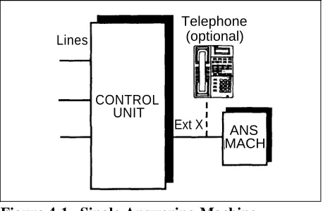
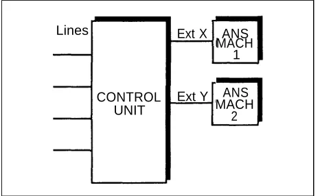
Overview
Answering Machines
Call Reporting Devices (SMDR) Credit Card Scanners
Fax Machines Modems
Night Service with Auxiliary Equipment PARTNER Attendant
Voice Messaging Systems
4-1 4-4 4-8 4-11 4-12 4-19 4-21 4-23 4-24
5
Feature Reference
5-i6
Troubleshooting
■ When You Need Help
■ Power Failure Operation ■ Problems with System Phones ■ Problems with Standard Phones ■ Problems with Combination Extensions
■ Other Problems with Phones
■ Problems with Standard Devices
■ System Problems
6-i 6-1 6-1 6-2 6-4 6-6 6-7 6-10 6-10
A
Specifications
A-1B
Maintenance, Repair, and
Ordering Information
B-1Contents
C
FCC Information
C-1D
Speed Dial Form
D-1GL
Glossary
GL-1I N
Index
IN-1Programming Quick References
Inside back coverAbout This Guide
Purpose
This guide is intended for the system manager. It explains what the PARTNER® Plus Communications System can do, provides instructions for programming and using the system, and tells how to get the most out of its many features and capabilities.
Terminology
Throughout this guide, the PARTNER Plus Communications System is referred to simply as the system and AT&T telephones specifically designed to work with the system are called system phones. You can also use industry-standard telephones with the system, which are referred to as standard phones in this guide. Finally, the PARTNER MAIL VS™ or PARTNER MAIL™ Voice Messaging System, which you may have connected to the system, is referred to as the
voice messaging system.
How to Use This Guide
For information on the following topics, refer to the appropriate chapter:
■
■
■
Getting Acquainted. Chapter 1 provides an overview of system features
and hardware components.
Programming the System. You can change your system’s settings
easily to accommodate new or expanding needs. Chapter 2 provides general programming information, while Chapter 5 provides detailed instructions for programming specific system features.
Training Co-Workers. Chapter 3 explains how system and standard
phones work with the system. To help train co-workers on telephone basics, you can share this information with them.
■
■
■
Using Auxiliary Equipment. The system supports a wide variety of
auxiliary equipment, including fax machines, modems, voice messaging systems, and call reporting devices. Chapter 4 provides advice on setting up these devices to work effectively with the system.
Daily Operation. Depending on how your system is set up, you may
need to oversee some of the system’s daily operations. For example, you may need to turn on Night Service at the end of each day before leaving the office. Reference information on all features, including descriptions and instructions for using each feature, is provided in Chapter 5.
Solving Problems. Chapter 6 provides information on solving problems
if your system or telephones malfunction.
Once you are experienced with the system, use the Table of Contents or Index to locate the information you need.
Throughout this guide, feature names are printed in bold so you can easily look up the name in Chapter 5, “Feature Reference,” for additional information on the feature. For example, if you see a reference to System Date (#101), you can look it up in Chapter 5 for details.
Product Safety Statements
Product safety statements are identified in this guide by a
CAUTION:
Indicates the presence of a hazard that will or can cause minor personal injury or property damage if the hazard is not avoided.
WARNING:
Indicates the presence of a hazard that can cause severe or fatal personal injury if the hazard is not avoided.
How to Comment on This Guide
A feedback form is located at the end of this guide, after the appendixes. If the form is missing, send your comments and recommendations for changes to Documentation Manager, AT&T, 200 Laurel Avenue (Room 4E-409),
Middletown, NJ 07748 (FAX 908 957-4009).
Overview
1
Contents
Important Safety Instructions
Features and Capabilities
System Components
■ Control Unit
System Modules System Capacity
■ Telephones
System Telephones Intercom Autodialers Standard Telephones
Auxiliary Equipment
■ Requirements
■ Connecting Standard Devices
ii 1-1 1-2 1-2 1-4 1-4 1-5 1-5 1-5 1-6 1-6 1-7 1-7
Important Safety Instructions
WARNING:
The following list provides basic safety precautions that should always be followed when using your telephone equipment:
1. 2. 3.
4.
5.
6. 7.
8.
9.
Read and understand all instructions.
Follow all warnings and instructions marked on the product.
Unplug all telephone connections before cleaning. DO NOT use liquid cleaners or aerosol cleaners. Use a damp cloth for cleaning.
This product should be serviced by (or taken to) a qualified repair center when service or repair work is required.
DO NOT use this product near water, for example, in a wet basement location
DO NOT place this product on an unstable cart, stand, or table. Never push objects of any kind into slots or openings as they may touch dangerous voltage points or short out parts that could result in a risk of fire or electric shock. Never spill liquid of any kind on the product.
Avoid using this telephone during an electrical storm. There may be a remote risk of electric shock from lightning.
DO NOT use the telephone to report a gas leak in the vicinity of the leak.
10. The product is provided with a three-wire grounding type plug. This is a safety feature. DO NOT defeat the safety purpose of the
grounding type plug. DO NOT staple or otherwise attach the AC power supply cord to building surfaces.
CAUTION:
DO NOT block or cover the ventilation slots and openings. They prevent the product from overheating. DO NOT place the product in a separate enclosure unless proper ventilation is provided.
SAVE THESE INSTRUCTIONS
Overview
1
Features and Capabilities
The following list provides an overview of the system’s features:
■
■
■
■
■ ■
■
■
■
Full line of system phones, providing access to multiple lines from a single phone at each extension.
Programmable buttons on system phones, providing one-touch access to system features simply by pressing the button.
Intuitive operation of basic call handling capabilities including transfer, conference, and hold.
Intercom (inside) calling to other system extensions using an Intercom button and the two-digit number assigned to the extension. Users can either ring or voice signal an idle system phone, or use Voice Interrupt On Busy to signal another user who is active on a call.
Grouping of extensions for flexibility in directing and answering calls. Integrated voice messaging support with the PARTNER MAIL VS system or PARTNER MAIL system, so callers can reach a desired extension or group without operator assistance and leave messages at unanswered or busy extensions.
Power failure operation with standard phones, allowing you to make and receive calls during a power failure while retaining programmed
equipment settings for up to four days. (An optional Uninterruptible Power Supply, or UPS, is also available to allow full equipment operation during a power failure.)
Centrex or PBX operation support—including one-touch dialing of feature access codes on system phones.
Flexible dialing restrictions and permissions so you can control telephone activity and phone bills.
■
■
■
■
■
■
Special hospitality features that let Bed and Breakfast proprietors, for example, regulate phone use in guest rooms and schedule wake up calls for guests.
Easy-to-use programming procedures, making it simple for you to manage your system and telephones. System display phones provide feedback during programming.
Two system programming extensions, allowing you to program the system from one extension without interrupting call activity at the other programming extension—usually the receptionist’s extension.
Modular connections to the control unit, making it easy to reconfigure your system or to add lines and/or extensions as your business grows. Direct connections for industry-standard devices—including most standard phones, fax machines, answering machines, modems, and credit card scanners.
Optional equipment support, including doorphones, loudspeaker paging systems, music on hold*, call reporting (often referred to as Station Message Detail Recording or SMDR) devices, PARTNER Attendant, and extra alerts.
System Components
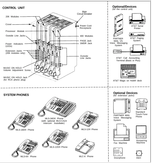
Modular hardware design makes the system easy to install and expand. Figure 1-1 shows an example of system components.
Control Unit
The control unit is the heart of the system; it includes a backplane and a cover, and it houses the system modules. All system modules slide into the
backplane, which channels power to the system. The cover slides onto the front of the backplane after all the system modules have been installed.
WARNING:
There are no customer-serviceable components inside the system modules or backplane. There are hazardous voltages within that can cause severe or fatal personal injury. DO NOT OPEN THE MODULES.
* If you use music-on-hold to broadcast certain copyrighted music or material, including songs or other material from radio broadcasts, you may be required to obtain the permission of the copyright owner. One way to obtain permission is to contact ASCAP, BMI, and/or similar performing rights organizations, to obtain a license. Or, you can purchase a Magic on Hold® system from AT&T, which does not require you to obtain such a license. AT&T disclaims any liability arising out of the failure to obtain such a license, if required.
CONTROL UNIT Optional/Devices(for the control unit)
Main Circuit Breaker
206 Modules
Cover
Power Cord Receptacle Processor Module
Outside Line Jacks 400 Modules
PAGE Jack SMDR Jack
Power Indicators Voice Messaging
System (LEDs)
Extension Jacks (206 modules only)
Outside
Line Jacks AT&T Call Accounting Terminal (Basic or Plus)
MUSIC ON HOLD Volume Adjustment Screw
MUSIC ON HOLD Jack
AT&T Serial Printer
PARTNER AT&T Paging
MAIL VS System
(for RCA phono plug) AT&T Magic on Hold® deck
SYSTEM PHONES
MLS-34D® Phone (with optional MLS-CA24
Intercom Autodialer)
MLS-12® Phone MLS-18D® Phone
MLS-12D® Phone
Optional Devices
(for extension jacks)
PARTNER MAIL Voice Messaging System
Fax Machine
Standard Touch-Tone Phone
Answering Machine
Alert
MLS-6® Phone MLC-6 Phone
Doorphone
Figure 1-1. Sample System Components
System Modules
The following system modules can be installed in your system:
■
■
■
Processor Module provides the software intelligence that controls the
system’s features. It has jacks for a music-on-hold audio source, a loudspeaker paging system, and a call reporting (SMDR) device, such as a printer.
206E Module has jacks to connect a maximum of two outside telephone
lines and six extensions to the system. You can connect telephones and other telecommunications devices (such as fax machines and modems) to the extension jacks (either directly or through your building’s modular wall jacks). Each 206E module has a green power indicator that shows it is receiving power. The system requires at least one 206E module.
400E Module is similar to the 206E module, but without extension jacks.
It has four outside line jacks. This module is an inexpensive way to add lines when you do not need more extensions.
If you are upgrading from a PARTNER system or a previous release of a PARTNER Plus system, you can still use its 200 modules, each providing two line jacks.
If you want message waiting capability on standard phones that are equipped with message waiting lights, you must connect those phones to extension jacks on Release 3.1 (R3.1) 206 modules. Additionally, you need an R3.1 processor module.
Hereafter, references to 206 modules include 206E and all 206 modules used with previous releases of the product. Similarly, references to 400 modules include 400E and all 400 modules used with previous releases of the product.
System Capacity
The combination of 206 and 400 modules installed determines the number of available lines and extensions. The system allows up to 12 lines and up to 24 extensions; however, these maximums cannot be achieved simultaneously:
■ For maximum line capacity (12 lines), install two 206 modules and two 400 modules. This arrangement allows up to 12 extensions.
■ For maximum extension capacity (24 extensions), install four 206
modules. This arrangement allows up to 8 lines.
Telephones
System Telephones
This guide refers to AT&T telephones specifically designed to work with the system as system phones. These include the MLS-34D, MLS-18D, MLS-12D, MLS-12, MLS-6, and MLC-6 telephones.
System phones have several buttons in common: volume control buttons, and the Feature , Conf , Transfer , and Hold buttons. In addition, each phone has
programmable buttons that can be used for outside lines, extension numbers,
outside phone numbers, or system features. Outside lines, as well as some system features, require buttons with status lights. Programmable buttons without lines assigned to them can be programmed with numbers or features, so you can use the feature or dial the number with one touch. The number in each model name indicates the number of programmable buttons with status lights plus two Intercom buttons.
If the system phone has a display, indicated by a “D” in the model name, users receive messages and prompts when making calls and programming. (More information about the display is provided in Chapter 5.) A system display phone is required for system programming. It must be as large as the largest phone in the system, because an MLS-12D or MLS-18D cannot program an MLS-34D. Similarly, an MLS-12D cannot program an MLS-18D.
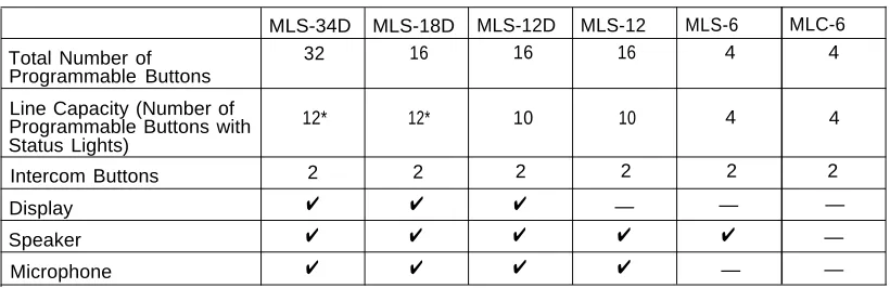
Table 1-1 summarizes system phone features.
Table 1-1. System Phones
MLS-34D MLS-18D MLS-12D MLS-12 MLS-6 MLC-6
Total Number of 32 16 16 16 4 4
Programmable Buttons Line Capacity (Number of
Programmable Buttons with 12* 12* 10 10 4 4
Status Lights)
Intercom Buttons 2 2 2 2 2 2
Display ✔ ✔ ✔ — — —
Speaker ✔ ✔ ✔ ✔ ✔ —
Microphone ✔ ✔ ✔ ✔ — —
Intercom Autodialers
The system phones at extensions 10 and 11 each support one MLS-CA24 Call Assistant™ Intercom Autodialer, which provides Auto Dial buttons for all of the extensions in your system (up to 24). The Auto Dial buttons allow users to dial and transfer calls to system extensions with one touch. The status lights for the buttons also indicate calling activity at each extension. For more
information, see “Auto Dialing” in Chapter 5.
* The MLS-34D has 32 programmable buttons with status lights and the MLS-18D has 16 programmable buttons with status lights. Since the system supports a maximum of 12 lines, you can use up to 12 buttons on these phones for outside lines.
Standard Telephones
You can also use industry-standard single-line rotary or touch-tone telephones, including feature phones with built-in feature buttons and lights, with the system. This guide refers to such telephones as standard phones. AT&T-certified standard phones, such as the 8110 Analog Telephone, are recommended. The following standard phones with message waiting lights are compatible with the system:
■
■
Single-Line Telephone with Message Waiting Light and Recall Button (2500 YMGK)
7102 Plus Analog Voice Terminal
Check with your local AT&T Authorized Dealer to find out if other standard phones with message waiting lights will work.
NOTE:
For message waiting capability, you must connect standard phones with message waiting lights to Release 3.1 (R3.1) 206 modules, and equip the system with an R3.1 processor module. This message waiting capability does not apply to standard phones with neon-type message waiting lights.
Auxiliary Equipment
You can connect many types of telecommunications devices to your system without expensive adapters or additional phone lines. Many industry-standard, single-line devices will work with the system regardless of the manufacturer:
■
■ ■ ■ ■
Touch-tone, rotary, and cordless telephones (such as those you might have in your home)
Fax machines Answering machines Modems
Credit card scanners
There are several other devices that may be compatible with the system. For more information, refer to the list in Chapter 4 or contact your local AT&T Authorized Dealer. Also, see Chapter 4 for advice on setting up auxiliary equipment to work effectively with the system.
Requirements
An industry-standard device must meet the following conditions:
It must be non-proprietary. That is, it cannot be made specifically for use on a particular telephone system. (For example, you cannot connect an AT&T MERLIN® phone because it is specifically designed for use on a MERLIN system.)
Its Ringer Equivalence Number (REN*) cannot be greater than 2.0. (The REN is shown on a label on the device, usually on the bottom.)
■
■
■ You can connect a standard two-line device to the system, but for best
results it should be installed and used as if it were a single-line device.
Connecting Standard Devices
You can connect a standard device so that it is on an extension by itself, or so that it shares an extension with another piece of equipment (either another standard device or a system phone) as long as the REN of the two devices together does not exceed 2.0. (System phones have 0.0 REN.) For example, you can connect a standard phone and an answering machine to the same extension. An extension with two devices connected to it is called a
combination extension. You cannot connect two system phones on one
extension. The PARTNER Plus Communications System Installation guide provides installation instructions.
* REN is a measure of the power it takes to ring a phone. The typical home phone line handles 4.0–5.0 RENs; each extension jack in your system handles up to 2.0 RENs.
Programming
2
Contents
Overview
Hardware Considerations
Initial System Setup
■ Setting the System Clock
■ Assigning Lines
■ Customizing Extensions
■ Copy Settings
Changing Settings after Installation
■ Changing the System Clock ■ Adding New Lines
■ Adding New Extensions ■ Swapping Extensions
Changing Settings to Support PBX or
Centrex Services
■ Recall Setting
■ Dialing Restrictions
■ Speed Dial and Auto Dial Numbers
System Programming Options
■ Speed Dialing
■ Dialing Restrictions and Permissions Restricting Access to Outside Lines Controlling Calls on Outside Lines Overriding Dialing Restrictions Summary
■ Setting Up Groups of Extensions ■ Setting Up Auxiliary Equipment
■ Hospitality Features
Contents
Using System Programming
■ The Programming Overlays
■ Programming Mode
■ Changing Programming Type
Telephone Programming Options
■ Automatic Line Selection
■ Extension Name on Display
■ Line Ringing
■ Personal Speed Dialing
■ Programming Telephone Buttons
■ Programming a Receptionist’s Extension
Call Handling Options Button Programming
Using Telephone Programming
■ Telephone Models
■ Using Centralized Telephone Programming
■ Changing Programming Type
■ Using Extension Programming
2-ii
Programming
2
Overview
After the system hardware is installed, you can customize the system and individual telephones. This chapter explains how to use programming to accomplish that.
There are two types of programming:
■ System Programming allows you to customize the system to meet the
needs of your business. When the system is first installed, it uses factory settings that reflect the most commonly used options. You can change system settings as needed.
You can perform System Programming from either extension 10 or 11. Because an extension cannot be in programming mode and handle calls at the same time, consider using extension 11 for programming. Doing so gives you the ability to program without disrupting call handling by the receptionist at extension 10.
■ Telephone Programming allows telephones to be customized to meet
individual users’ needs. Individual telephones can be programmed either from extension 10 or 11 (called Centralized Telephone Programming), or from a user’s extension using a system phone (called Extension
Programming).
A system display phone is required for System and Centralized Telephone Programming. Make sure that the programming phone is as large as the largest phone in the system, because an MLS-12D or MLS-18D cannot program an MLS-34D. Similarly, an MLS-12D cannot program an MLS-18D.
This chapter provides general information on programming procedures. When a specific feature name is referenced, it is printed in bold type. For detailed descriptions and step-by-step instructions, refer to that name in Chapter 5. (Brief summaries of all programming procedures are at the end of this book.)
Hardware Considerations
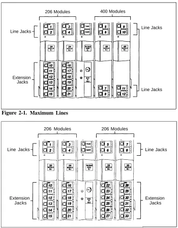
Programming procedures use line and extension numbers. The line number represents the line jack on a 206 or 400 module to which the outside line is connected. Similarly, the extension number represents the extension jack on a 206 module to which the system phone or standard device is connected. For each 206 module, the system assigns two lines and six extensions; for each 400 module, the system assigns four lines. The system numbers lines and extensions consecutively. Figure 2-1 shows the numbering scheme for a system with maximum lines. Figure 2-2 shows the numbering scheme for a system with maximum extensions. However, your system can have any number of lines and extensions up to the maximum.
206 Modules 400 Modules
Line Jacks
Extension Jacks
Line Jacks
Line Jacks
Figure 2-1. Maximum Lines
206 Modules 206 Modules
Line Jacks Line Jacks
Extension Jacks
Extension Jacks
Figure 2-2. Maximum Extensions
Initial System Setup
After the control unit is installed, you set up the system using a combination of system and telephone programming procedures. In this guide, System Programming procedures are identified by a code (# and three digits); Telephone Programming procedures are identified by the feature name only. Use the System Planner as a guide when programming. The following sections provide an overview of the procedures you use for initial system setup. See Chapter 5 for more information on specific procedures. Other programming procedures are optional, but strongly recommended to make the most of your investment. (See “System Programming Options” and “Telephone Programming Options” later in this chapter for details.)
Setting the System Clock
After supplying power to the control unit, use the following procedures:
■ System Date (#101) to set the month and day. ■ System Day (#102) to set the day of the week. ■ System Time (#103) to set the hour and minutes.
Assigning Lines
For initial setup only, use Number of Lines (#104) to specify the number of lines that will be assigned to all system extensions. Then use the following
procedures as needed:
■
■
■
■
■
Dial Mode (#201) to identify any rotary lines (the default for all lines is
“touch-tone”).
Line Assignment (#301) to assign lines to specific extensions (if the line
was not assigned using the Number of Lines procedure), to remove lines from some extensions, or to change the button used to pick up a line at a specific extension.
Line Access Restriction (#302) to limit an extension’s access to a
specific line.
Line Ringing (Centralized Telephone Programming) to specify when a
line will start ringing at each extension that has the line. For additional information on line ringing options, see “Programming a Receptionist’s Extension” later in this chapter.
Automatic Line Selection (Centralized Telephone Programming) to
specify the order in which the system tries to select an available line (intercom or outside), when a user at the extension lifts the handset or presses Spkr to make a call without first selecting a specific line button.
For extensions with standard phones, set Automatic Line Selection to intercom first. This enables standard phones to access equipment features, including intercom calling. When users lift the handsets on standard phones, they hear intercom dial tone. To access an outside line, they must dial 9.
Customizing Extensions
In addition to line assignments, the following procedures can be used to customize an extension:
■
■
■
■
■
■
■
■
Display Language (#303) to specify the language (English, French, or
Spanish) for messages that appear on a system display phone.
Automatic Extension Privacy (#304) to prevent other extensions with
the same line from joining a call at the extension. This feature is also useful for extensions connected to a modem, fax, or any device whose function can be disrupted by someone trying to join it.
Forced Account Code Entry (#307) to prevent the extension from
making an outside call until a required account code is entered. You can also use Forced Account Code List (#409) to create a list of valid account codes.
Outgoing Call Restriction (#401) to prevent the extension from making
certain types of outgoing calls (on all system lines).
Disallowed List Assignments (#405) to assign one or more Disallowed
Phone Number Lists to the extension. Use Disallowed Phone Number
Lists (#404) to create the lists of outside numbers that extensions cannot
dial.
Allowed List Assignments (#408) to assign one or more Allowed Phone
Number Lists to the extension. Use Allowed Phone Number Lists (#407) to create the lists of outside numbers that otherwise-restricted extensions
can dial.
Pickup Group Extensions (#501), Calling Group Extensions (#502), Night Service Group Extensions (#504), and Hunt Group Extensions (#505) to place the extension in any of these groups. See “Setting Up
Groups of Extensions” later in this chapter for more information.
Fax Machine Extensions (#601), Doorphone Extension (#604 and #605), Doorphone Alert Extensions (#606), or AA Extensions (#607) to
identify the extension as one of these equipment types.
“Setting Up Auxiliary Equipment” later in this chapter provides an overview of the procedures you use for setting up devices, such as hotline phones, voice messaging systems, and call reporting devices. Also, Chapter 4 provides detailed information and example applications for auxiliary equipment.
Copy Settings
The recommended way to set up your system is to program one extension for each type of phone in the system, then use Copy Settings (#399) to program other phones of the same type. For example, you can program one MLS-12D phone and then copy its settings to any other extensions that have MLS-12D or MLS-12 phones. See “Copy Settings” in Chapter 5 for a list of the programmed settings that are copied.
Changing Settings after Installation
As your business grows or changes, you will probably need to change the way your system was originally programmed. This section provides some examples and lists the procedures you would use to change settings after installation. For specific details on a procedure, refer to the procedure name in Chapter 5.
Changing the System Clock
You may need to change the system clock for daylight saving time, after a prolonged power failure, or after a system reset. Use System Date (#101),
System Day (#102), and System Time (#103) to set the current date, day, and
time.
Adding New Lines
If you add an outside line to your system, you may need to adjust some line settings. In particular, use Dial Mode (#201) if the new line is a rotary line, Line
Assignment (#301) to assign the line to specific extensions, Line Ringing
(Centralized Telephone Programming) to specify when the line will start ringing at each extension that has the line, and Line Access Restriction (#302) to limit an extension’s access to the line. Additionally, the system automatically assigns the new line as the last line in the Automatic Line Selection sequence. If you want to change the order, use Automatic Line Selection (Centralized Telephone Programming).
IMPORTANT:
Do not use Number of Lines (#104) if you add lines to the system after initial setup, because it changes Line Access Restriction (#302), Automatic Line
Selection, Line Ringing, and Hold Disconnect Time (#203) for existing lines
back to factory settings. To change line assignments without affecting other settings, use Line Assignment (#301).
Adding New Extensions
If you add an extension to your system, you can probably use Copy Settings
(#399) to copy the settings of an existing extension. If you wish to further adjust
a new extension’s settings, see “Customizing Extensions” earlier in this chapter.
Swapping Extensions
If a user changes physical locations but wants to keep the same extension number, you can make the change easily by swapping modular connections at the control unit.
For example, if the users at extensions 29 and 32 switch offices, you can disconnect the modular plug from extension jack 29 in the control unit, and reconnect it at extension jack 32. Likewise, unplug the wire that was connected to extension jack 32 and reconnect it at extension jack 29. Then, the users can take their respective phones to their new location to keep the same extension number and retain the phone’s programmed settings.
Changing Settings to Support
PBX or Centrex Services
■
■
This section applies only if you use PBX or Centrex services with your system. If it does not apply, go to the next section, “System Programming Options.”
PBX services are provided by a private telephone switch.
Centrex services are provided by your local telephone company from a Central Office (CO) outside your premises. These services include the Centrex lines connected to your control unit modules and some set of features—such as hold, conference, or transfer—that are available on those lines. Centrex services may be offered in your area under a different name. For specific Centrex features to be available to you, your company must subscribe to those features. For specific information on using Centrex, see the Centrex documentation provided by your local telephone company.
Some of the issues you should consider when setting up your system to work effectively behind a PBX or Centrex system are discussed below. Chapter 5 explains how to use the programming procedures discussed here.
Recall Setting
To set up your equipment to work properly with a PBX or Centrex system, first set Recall Timer Duration (#107) to match the setting used by your PBX or Centrex system (usually 800 msec., or “32”). This setting affects the length of a Recall signal sent by the control unit to access Centrex services.
Dialing Restrictions
Outgoing Call Restriction (#401) is an equipment restriction intended to limit
an extension’s dialing to “inside calls only” (using the Intercom buttons on
system phones) or to “inside and local calls only” (allowing calls within the PBX or Centrex system and local calls outside the PBX or Centrex system).
However, if users in your system use a dial-out code (9 on most PBX or Centrex systems) before dialing numbers outside the PBX or Centrex system, the
equipment will not be able to prevent toll calls for extensions restricted to “inside and local calls only” (unless you use Disallowed Phone Number Lists to prevent dialing to specific classes of numbers).
If your PBX or Centrex system includes dialing restrictions, use those instead of the equipment restrictions. If you have PBX or Centrex dialing restrictions on a line and also program equipment restrictions, both the PBX or Centrex system and equipment restrictions apply. However, equipment dialing permissions will
not override PBX or Centrex system restrictions.
Speed Dial and Auto Dial Numbers
When you program numbers outside the PBX or Centrex system as Speed Dial and Auto Dial numbers, include the PBX or Centrex system dial-out code (9 on most PBX or Centrex systems), followed by a pause, in the stored number.
System Programming Options
This section discusses programming options that involve multiple procedures (such as dialing restrictions and auxiliary equipment settings), as well as
features that can be used throughout your system (such as Speed Dialing). You can use a combination of programming procedures to set up your system to operate most efficiently, taking into account your company’s telephone service, personnel, and equipment, as well as the special needs of particular
departments. This section lists the procedures you can use; for details on using a particular procedure, refer to the procedure name in Chapter 5.
Speed Dialing
You can program up to 60 frequently dialed phone numbers—such as suppliers, repair services, customers—so that all users in the system can dial them by pressing three buttons: Feature (or # on a standard phone) plus a
two-digit code. These are called System Speed Dial Numbers.
Dialing Restrictions and Permissions
The system has several procedures for restricting telephone use, and several for overriding those restrictions. You can use any combination of these procedures to design a system that meets your needs.
When a user makes a call, the system checks the number dialed against all of the dialing restrictions that apply to the extension making the call. When the number dialed passes a restriction, it goes to the next one, if necessary. When a number violates a restriction, the call is stopped and the user hears a reorder
tone (fast busy signal).
IMPORTANT:
While procedures that restrict dialing are very effective, absolute protection against misuse cannot be guaranteed. System phones give more protection than standard phones. Therefore, we strongly recommend that you install system phones where restricting phone use is important.
Restricting Access to Outside Lines
A user can access a line either by pressing the line button on the phone or by dialing a feature code (Direct Line Pickup). If you do not want a user to access a specific outside line, you can use Line Access Restriction (#302) to control an extension’s access to a certain line (whether the line is assigned to the extension or not). Table 2-1 provides examples of settings that can be used to restrict an extension’s access to a specific outside line.
NOTE:
If Forced Account Code Entry (#307) is programmed for an extension, that extension is required to enter an account code before dialing an outside number—even those on the Emergency Phone Number List (#406) — on all of the lines assigned to that extension. If Forced Account Code List (#409) contains entries, the system checks the account code against the list. If the account code is on the list, line access is allowed; if not, line access is denied.
Controlling Calls on Outside Lines
When an extension is allowed access to an outside line, you can use the following procedures to control calling:
■
■
■
Outgoing Call Restriction (#401) defines the type of calls (inside only,
local only, or inside, local, and long-distance) that users can make from
all lines available on an extension. Outgoing Call Restriction Button
(#114) allows the receptionist at extension 10 to quickly change an
extension’s current Outgoing Call Restriction setting.
Disallowed Phone Number Lists (#404) creates up to four lists of
numbers that cannot be dialed. After creating Disallowed Phone Number Lists, use Disallowed List Assignments (#405) to assign one or more lists to a specific extension.
Night Service with System Password (#403) restricts users at
extensions in the Night Service group from dialing outside phone numbers (except Emergency numbers and Marked System Speed Dial numbers) unless the password is entered first.
Table 2-2 provides examples of settings that can be used to restrict an extension’s dialing once it gets an outside line.
Overriding Dialing Restrictions
The following programming procedures provide ways to override all dialing restrictions, provided the user has access to an outside line:
■
■
■
Emergency Phone Number List (#406) defines a list of up to ten
numbers that can be dialed from any extension. A typical number is 911. Marked System Speed Dial Numbers are specially identified System Speed Dial numbers, which a user can dial by pressing Feature (or #
on a standard phone) followed by a two-digit code.
System Password (#403) creates a password that can be entered at any
system phone (except an MLC-6) to override dialing restrictions for the duration of a call.
To override all dialing restrictions except Line Access Restriction (#302) and
Night Service with System Password (#403), use Allowed Phone Number Lists (#407) to create lists of outside numbers that otherwise-restricted
extensions can dial. Then use Allowed List Assignments (#408) to assign one or more of the lists to an extension.
Summary
Tables 2-1 and 2-2 summarize the available dialing restrictions and permissions, showing how they can be combined in a variety of ways to customize an
extension’s dialing privileges.
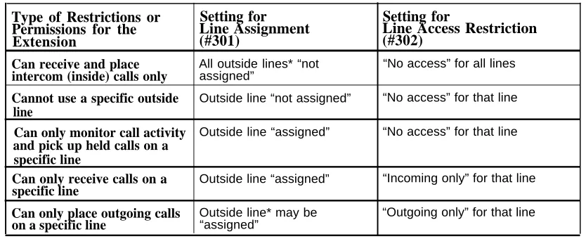
Table 2-1. Settings that Restrict an Extension’s Access to a Specific Line
Type of Restrictions or
Setting for
Setting for
Permissions for the
Line Assignment
Line Access Restriction
Extension
(#301)
(#302)
Can receive and place All outside lines* “not “No access” for all lines intercom (inside) calls only assigned”
Cannot use a specific outside line
Can only monitor call activity and pick up held calls on a specific line
Can only receive calls on a specific line
Can only place outgoing calls on a specific line
Outside line “not assigned” “No access” for that line Outside line “assigned” “No access” for that line
Outside line “assigned” “Incoming only” for that line Outside line* may be “Outgoing only” for that line “assigned”
Table 2-2. Settings that Restrict an Extension’s Dialing Once It Gets an Outside Line
Type of
Restrictions or
Permissions for
the Extension
Setting for
Line
Assignment
(#301)
Can place intercom and local calls only (and can answer any call) Outside line* may be “assigned” Can place intercom, local and long-distance calls (and can answer any call) Outside line* may be “assigned”Setting for
Line Access
Restriction
(#302)
“No restriction” “No restriction”Setting for
Outgoing Call
Restriction
(#401)
Setting for
Disallowed
Phone Number
Lists (#404)
“Local only” Any local numbers the extension should not dial
“No restriction” Any local and long-distance numbers the extension should not dial
* If a line is not assigned to the extension, a user can use Direct Line Pickup to access the line. Emergency numbers, Marked System Speed Dial numbers, Allowed Phone numbers, and numbers dialed using the System Password override all dialing restrictions if a user has access to an outside line to place the call. If Forced Account Code Entry is programmed for an extension, the user must enter an account code before accessing an outside line. If there are entries in the Forced Account Code List, the entered account code must match an entry on that list.
Setting Up Groups of Extensions
You can set up four types of extension groups:
■
■
■
■
Pickup Group Extensions (#501) assigns extensions to one of four
Pickup Groups. A Pickup Group lets any user in the system answer outside calls for any extension in that group.
Calling Group Extensions (#502) assigns extensions to one of four
Calling Groups. A Calling Group lets users ring or page all extensions in that group simultaneously.
Night Service Group Extensions (#504) assigns extensions to the Night
Service Group. When Night Service is activated at extension 10, calls ring immediately at Night Service extensions regardless of how they ring at other times (only the lines assigned to an extension will ring).
Hunt Group Extensions (#505) assigns extensions to one of seven Hunt
Groups. (Hunt Group 7 is used exclusively for the voice messaging system.) A Hunt Group lets users ring or voice signal the first available (non-busy) extension in that group. If a ringing call is not answered, the system tries each available extension in turn until the call is answered. If a voice-signaled call is not answered, the call does not keep hunting. Also use Group Call Distribution (#206) to assign outside lines to a Hunt Group if you want outside calls to ring directly into a group.
Setting Up Auxiliary Equipment
The following programming procedures help you manage auxiliary equipment. See Chapter 4 for more information on auxiliary equipment configurations or refer to Chapter 5 for details on using the procedure:
■
■
■
■
■
Fax Machine Extensions (#601) identifies extensions to which fax
machines are connected.
Music on Hold (#602) activates or deactivates the MUSIC ON HOLD jack
on the processor module. When this jack is activated and an audio source is connected, callers hear recorded music or messages while on hold. Also, Background Music lets users with system phones (other than the MLC-6) play the recorded material through their phone’s speaker when the phone is not in use.
Hotline (#603) identifies hotline extensions, so when a person lifts the
handset of the hotline phone, a predetermined extension automatically rings.
Doorphone Extension (#604 and #605) identifies extensions to which
doorphones are connected. Doorphone Alert Extensions (#606) identifies extensions that signal when the doorphone button is pressed.
AA Extensions (#607) identifies extensions to which PARTNER
Attendants are connected. This lets the system notify users with display phones when they are receiving a call that has been transferred from the PARTNER Attendant. Also, Transfer Return Extension (#306) lets you identify the extension to which a call transferred by the PARTNER Attendant should be routed if the destination extension does not answer.
■
■
SMDR Record Type (#608) specifies the type of calls that you want to
record for call reporting—either all calls or outgoing calls only. Account
Code Entry lets users specify account codes for outside telephone calls;
if used, the account codes are included on the call report. SMDR Top of
Page (#609) notifies the system that the printer has been aligned to the
top of a new page.
The voice messaging system uses the following procedures:
– Hunt Group Extensions (#505) assigns the extensions associated
with the voice messaging system hardware to Hunt Group 7—the VMS Hunt Group. (The PARTNER MAIL VS system uses two extensions; the PARTNER MAIL system uses two or four extensions.)
– Group Call Distribution (#206) assigns lines to the VMS Hunt Group
so calls can ring directly into the voice messaging system and receive Automated Attendant Service or directly into the voice mailbox of a specific subscriber.
– VMS Hunt Delay (#506) determines when outside calls should be
answered by the Automated Attendant Service of the voice messaging system. You can set the system for either immediate call handling or delayed call handling. The setting you select is used for both day and night operation.
– VMS Hunt Schedule (#507) determines when outside calls should
ring the VMS Hunt Group (always, day only, or night only) depending on the status of the Night Service Button (#503) at extension 10. – Automatic VMS Cover (#310) determines whether or not an
extension’s unanswered intercom and transferred calls are automatically covered by the voice messaging system.
– Transfer Return Extension (#306) identifies the extension to which a
call transferred by the voice messaging system should be routed if the destination extension does not answer and does not have voice mail coverage active. (The transfer return extension for the voice
messaging system is typically extension 10.)
Hospitality Features
The following hospitality features are for special applications, such as the Bed and Breakfast and Hotel/Motel industries:
■
■
Outgoing Call Restriction Button (#114) lets you program a button on
the system phone at extension 10 to change an extension’s current Outgoing Call Restriction setting without entering System Programming mode. For example, after a guest’s departure, a hotel manager can change the No Restriction setting of the guest room phone to Inside Only so outside calls cannot be made from the phone after the guest checks out.
Wake Up Service Button (#115) lets you program a button on the system
phone at extension 10 to be used for scheduling wake-up or reminder calls for specified system extensions.
Using System Programming
System Programming changes settings for the system as a whole, or for individual lines or extensions. You can also use System Programming to set up dialing restrictions, define groups, or set up auxiliary equipment. Refer to the filled-out System Planner when you are changing system settings, and be sure that any changes in programming are recorded there.
The Programming Overlays
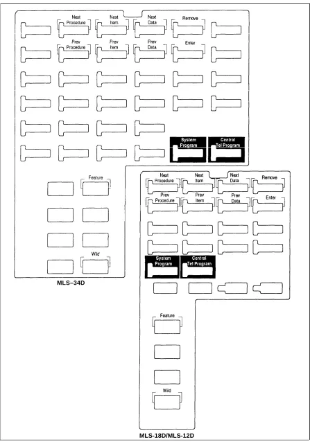
System Programming requires a programming overlay placed over the dial pad of the MLS-34D, MLS-18D, or MLS-12D system phone at extension 10 or 11. (Overlays are provided with the system documentation. Replacements can be ordered through the AT&T Sourcebook.) Figure 2-3 illustrates the programming overlays.
During System Programming, the normal functions of several buttons on the display phone at extension 10 or 11 change. For example, the left Intercom
button becomes System Program , the button used to enter programming mode.
The programming overlay identifies these buttons. You use the following special buttons while programming:
■
■
■
■
■
■ ■
■ ■
Next Procedure and Prev Procedure cycle forward and backward through the programming procedures. You can use these buttons to select a procedure.
Next Item and Prev Item cycle forward and backward through a
procedure’s parameters. A parameter is typically an outside line, an extension, or a telephone list entry.
Next Data and Prev Data cycle forward and backward through the valid
entries. These buttons work only for fixed data, such as a line or
extension number. They do not work for variable data such as date, time, password, telephone numbers, or doorphone assignments.
Remove returns the current setting to the factory setting—or when using Line Assignment (#301), removes lines from an extension.
Enter ends an entry of variable length, such as a telephone number in an
Allowed Phone Number List.
System Program starts the System Programming process.
Central Tel Program starts the Centralized Telephone Programming process
(to customize individual telephones centrally from extension 10 or 11).
Feature when followed by 0 0 , enters or exits programming mode.
Wild enters a “wildcard” (a character that matches any digit dialed) in
telephone numbers in Allowed Phone Number Lists (#407), Disallowed
Phone Number Lists (#404), and the Forced Account Code List (#409).
MLS–34D
MLS-18D/MLS-12D
Figure 2-3. Programming Overlays for System Display Phones
Programming Mode
1. Place the Programming Overlay over the dial pad of the system display phone at extension 10 or 11—see “The Programming Overlays” earlier in this
chapter for more information.
2. To enter programming mode, press Feature 0 0 . The display reads:
PROGRAM EXT 10
If you are programming from extension 11, “11” displays instead of “10.” 3 . Press System Program . The display reads:
10 Enter name
This display is for the Extension Name Display feature. When you are entering System Programming mode, skip it by moving on to Step 4. 4. Press System Program again. The display reads:
SYSTEM PROGRAM
5. Specify a programming procedure in one of two ways:
■ Direct Method to dial the code for that procedure. System
Programming procedures in this guide are identified by # and a three-digit code (for example, System Date is #101). This method is best when you are using only a few procedures during a programming session and you know the codes.
■ Cycle Method to cycle through the procedures in numerical order.
Press Next Procedure and Prev Procedure to cycle forward and backward
through the programming procedures. This method is best when you are using multiple procedures during a programming session, or if you do not know the codes.
6. To exit programming mode, you can press Feature 0 0 or lift the handset
off-hook, then place it back in the cradle.
NOTE:
You can talk on the phone while you program. This is useful if you need to talk with someone at the AT&T Helpline about programming. However, you must call before you enter programming mode, and you must use the handset to talk, not the speaker and microphone.
Changing Programming Type
When you are in programming mode, you can move between System Programming and Centralized Telephone Programming. To change to Centralized Telephone Programming when you are in System Programming, press Central Tel Program . To move back to System Programming when you are
in Centralized Telephone Programming, press Central Tel Program then
System Program .
Telephone Programming Options
System telephones are ready to use when they are installed, but they can be customized to meet the needs of your business and individual users. This customization is accomplished through Telephone Programming.
Automatic Line Selection
When a user lifts the telephone’s handset or presses Spkr , the system chooses
an idle line automatically. Automatic Line Selection determines the order in which the system looks for an idle line. You can set the system to look for lines in any desired order. For standard phones or for any phone used mainly to call other extensions, select an inside (intercom) line first.
Extension Name on Display
With Extension Name Display, users can assign a name (up to 12 characters long) to their extension. Then, when those users make an intercom call, group call, or transfer a call, their name and extension number appears on the display phone receiving the call. Similarly, users receiving a transfer return call see the name and extension number of the person assigned to the extension that did not answer the transferred call.
Line Ringing
Line Ringing defines when each outside line rings at a phone. For each line at
an extension, you can specify Immediate Ring, Delayed Ring (phone rings after a 20-second delay), or No Ring.
Personal Speed Dialing
Personal Speed Dial numbers are outside phone numbers that a user dials by pressing Feature (or # on a standard phone) plus a two-digit code. Unlike
System Speed Dial numbers, which are available to all users in the system, Personal Speed Dial numbers are available only at the extension for which they are programmed. Users can store up to 20 Personal Speed Dial numbers.
Programming Telephone Buttons
Telephone buttons without lines assigned to them can be programmed for system features such as Exclusive Hold or Conference Drop or for telephone numbers, so you can use the feature or dial the phone number with one touch. Once programmed, these buttons are called Auto Dial buttons, because simply pressing the button automatically dials the feature code or the telephone number.
A user who has a system phone with programmable buttons should consider programming them with a combination of frequently used features and outside and intercom telephone numbers.
Programming a Receptionist’s Extension
Call Handling Options
If you set up a centralized telephone answering position at extension 10, use the following settings to customize it:
■
■
■
Immediate Call Answering. If the receptionist should answer all calls,
use Line Assignment (#301) to assign all lines to extension 10. Set Line
Ringing for all lines at extension 10 to Immediate Ring; set the lines
assigned at each user’s extension to Delayed Ring or No Ring.
Backup Call Answering. If the receptionist should answer some lines
only when a user does not pick up, set Line Ringing for those lines at
extension 10 to Delayed Ring; set the lines assigned at each user’s extension to Immediate Ring.
No Answering. If some lines should not be picked up by the receptionist
at all, either set Line Ringing for those lines at extension 10 to No Ring or simply use Line Assignment (#301) to remove those lines from extension 10. In either case, set Line Access Restriction (#302) to No Access for those lines at extension 10 to prevent the receptionist from using Direct Line Pickup to access those lines.
Button Programming
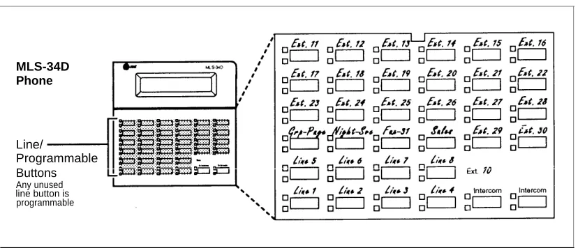
The MLS-34D phone shown in Figure 2-4 illustrates the following programmed buttons in addition to some other system features:
■
■
Extension Numbers. Auto Dial buttons are programmed for extensions
11 through 30, starting with the top left button shown in Figure 2-4. The receptionist can use these buttons to dial or transfer calls to the extensions with one touch. In addition, the lights of the Auto Dial button show the status of the extension, so the receptionist can tell whether the phone at the extension is idle (no lights on), busy (red on), calling the receptionist (green flash), or ringing back after the receptionist transferred a call (green flutter).
Fax Management. A button (labeled Fax-31) is programmed as a Fax
Management button for the fax machine connected to extension 31. The lights next to the button show what is happening at the fax machine (for example, red broken flutter indicates that the fax machine is not
responding—like when it is out of paper). (For more information, see “Fax Management Feature” in Chapter 4.)
Alternatively, the receptionist can use an MLS-CA24 Intercom Autodialer for the extensions the receptionist dials most frequently. This leaves buttons on the phone free for more features and phone numbers.
MLS-34D Phone
Line/
Programmable Buttons Any unused line button is programmable
Figure 2-4. Button Programming for Receptionist’s Phone
Using Telephone Programming
There are two ways to program a telephone: Centralized Telephone
Programming from extension 10 or 11 (see below) and Extension Programming
from a user’s own extension (see page 2-20).
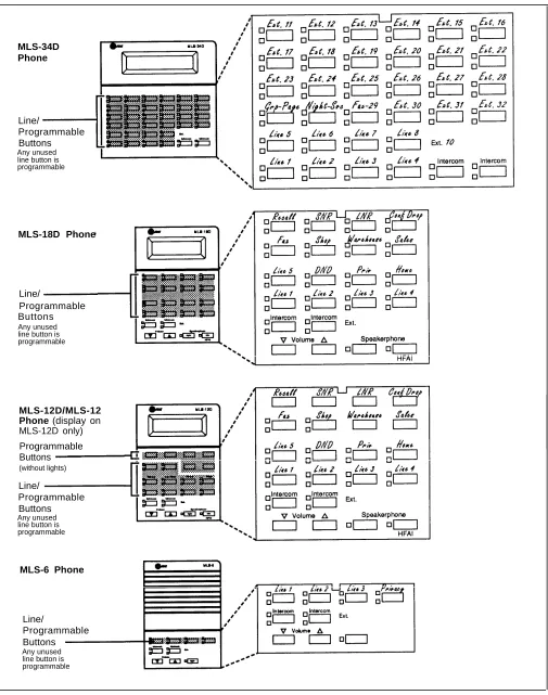
Telephone Models
Figure 2-5 illustrates an MLS-34D, MLS-18D, MLS-12D/MLS-12, and MLS-6 phone. As you program buttons, mark their functions on the phone’s labeling sheet (see the examples in Figure 2-5).
NOTE:
An MLS-6 phone with 4 lines assigned to it has no buttons available for
programming. The MLC-6 cordless phone looks just like an MLS-6 phone when you program it centrally.
Using Centralized Telephone Programming
Use Centralized Telephone Programming to program features or store telephone numbers for individual extensions from extension 10 or 11. Most features also can be programmed on a system phone at the user’s extension. Keep in mind the following exceptions:
■
■
■
Automatic Line Selection and Line Ringing always must be
programmed using Centralized Telephone Programming.
If a user has a standard phone, Personal Speed Dial Numbers for the extension can be programmed only by using Centralized Telephone Programming.
If a user has a standard phone or a non-display system phone,
Extension Name Display for the extension can be programmed only by
using Centralized Telephone Programming.
During Centralized Telephone Programming, the display phone at extension 10 or 11 takes on the characteristics of the telephone being programmed, including any System Programming settings and lines assigned to the phone. Make sure the programming phone is as large as the largest phone in the system, because an MLS-18D phone cannot program an MLS-34D phone and an MLS-12D phone cannot program an MLS-18D phone or an MLS-34D phone.
To program a phone from extension 10 or 11, use the following procedure: 1.
2.
3.
4.
Place the Programming Overlay over the dial pad of the system display phone at extension 10 or 11—see “The Programming Overlays” earlier in this
chapter for more information. To start programming: a.
b.
c.
d.
Press Feature 0 0 . The display reads:
PROGRAM EXT 10
If you are programming from extension 11, “11” displays instead of “10.” Press System Program . The display reads:
10 Enter name
This display is for the Extension Name Display feature. When you are entering Centralized Telephone Programming mode, skip it by
moving on to Step 2c.
Press System Program again. The display reads: SYSTEM PROGRAM
Press Central Tel Program . The display reads:
CENTRAL TEL PROG Extension:
Dial the extension number of the telephone to be programmed.
Buttons on which lines are assigned for the extension light up to show the current Line Ringing settings; remaining buttons can be programmed with telephone numbers, extension numbers, or system features.
At this point, you can:
■
■
■
Use Automatic Line Selection to change the order in which the telephone tries to select a line when the user picks up the handset. (If you want to change Automatic Line Selection for an extension, you must do so immediately after you enter programming mode and dial the extension number.)
Use Extension Name Display to assign a user’s name to the extension. (Like Automatic Line Selection, this procedure must be done immediately after you enter programming mode and dial the extension number. If you want to change both Automatic Line Selection and Extension Name Display, first change Automatic Line Selection, then press Central Tel Program and return to Step 3, redial the extension number, then use Extension Name Display.)
Use Line Ringing to change the ringing for an individual line.
MLS-34D Phone
Line/
Programmable Buttons Any unused line button is programmable
MLS-18D Phone
Line/
Programmable Buttons Any unused line button is programmable
MLS-12D/MLS-12 Phone (display on MLS-12D only) Programmable Buttons (without lights)
Line/
Programmable Buttons Any unused line button is programmable
MLS-6 Phone
Line/
Programmable Buttons Any unused line button is programmable
Figure 2-5. Programmable Buttons and Labeling Sheets on System Phones
5.
6.
7.
Program Personal Speed Dial Numbers, Auto Dial numbers, or system features as described in Chapter 5.
To erase the current programming from a button, press the button, then press Mic .
To change the settings for another extension, press Central Tel Program , then
dial the new extension number.
To exit programming mode, you can press Feature 0 0 , or lift the handset
off-hook, then place it back in the cradle.
Changing Programming Type
When you are in programming mode, you can move between System
Programming and Centralized Telephone Programming. To change to System Programming when you are in Centralized Telephone Programming, press
Central Tel Program then System Program . To move back to Centralized Telephone
Programming when you are in System Programming, press Central Tel Program .
Using Extension Programming
Users can program features or store numbers on buttons from their own phones using Extension Programming. Keep in mind the following exceptions:
■
■
■
Automatic Line Selection and Line Ringing always must be
programmed using Centralized Telephone Programming.
If a user has a standard phone, Personal Speed Dial Numbers for the extension can be programmed only by using Centralized Telephone Programming.
If a user has a standard phone or a non-display system phone,
Extension Name Display for the extension can be programmed only by
using Centralized Telephone Programming.
To program at the extension, use the following procedure: 1.
2.
3.
4.
To start programming, dial Feature 0 0 .
Buttons on which lines are assigned for the extension light up to show the current Line Ringing settings. Remaining buttons can be programmed with telephone numbers, extension numbers, or system features.
To assign a name to the extension, press left Intercom , then enter the character codes. See Extension Name Display in Chapter 5 for the codes.
Program Personal Speed Dial Numbers, Auto Dial numbers, or system features as described in Chapter 5.
To erase the current programming from a button, press the button, then press Mic .
To exit programming mode, you can press Feature 0 0 , or lift the handset
off-hook, then place it back in the cradle.
Learning About Telephones
3
Contents
System Telephones
■ Buttons and Indicators
■ Lights
■ Ringing Patterns ■ Dial Tones
■ Using the Handset, Speaker, and Microphone Hands-Free Answer on Intercom (HFAI) Voice Interrupt on Busy Calls
Speakerphone Performance Tips
Standard Telephones
■ Ringing Patterns
■ Dial Tones
■ Using the Switchhook
■ Limitations
■ Feature Phones
Combination Extensions
Using Telephones
■ Basic Call Handling Features
■ Dial-Code Features
3-1 3-2 3-4 3-5 3-5 3-5 3-6 3-7 3-7 3-7 3-8 3-9 3-9 3-9 3-10 3-10 3-11 3-11 3-12
Learning About Telephones
3
This chapter explains how system and standard phones work with the system, as well as combination extensions where more than one phone or standard device is installed. System phones are described first, followed by standard phones on page 3-7 and combination extensions on page 3-10. In addition, call handling features are listed on page 3-11. See the feature name in Chapter 5 for details on a specific feature.
System Telephones
System phones, which include the MLS-34D, MLS-18D, MLS-12D, MLS-12, MLS-6, and MLC-6 models, have several buttons and indicators in common. The following pages expl