Development of Appointment Scheduling Agent Using Distributed
Constraint Satisfaction (DisCS)
PEMBANGUNAN AGEN PENJADUALAN TEMUJANJI MENGGUNAKAN KEPUASAN KEKANGAN TERAGIH (DisCS)
NURULHUDA FIRDAUS MOHD AZMI ZETI DARLEENA ERI
NUZULHA KHILWANI IBRAHIM ROZANA DIANA AHMAD RUSLI
RESEARCH VOTES NUMBER: 79107
Pusat Pengurusan Penyelidikan
Universiti Teknologi Malaysia
2008
DEDICATION
In the name of ALLAH the most merciful and compassionate. Salawat and salaam to our great prophet Muhammad S AW and his family and friends. May ALLAH bestow His blessing upon their souls. All the praises and gratefulness to ALLAH of because for His blessing and willing may this paper be presented today.
Our highest appreciation dedicated to the Ministry of Scien ce, Technology and
Innovation (MOSTI) for the grant that was made available for us to carry out this study.
Our big thank you to Centre of Research Management, UTM for the support and guidance in managing this research grant.
To all the researchers, Pn Zeti Darleena bt Eri, Cik Nuzulha Khilwani Bt Ibrahim and Cik Rozana Diana Bt Ahmad Rusli, thank you very much for all the fruitfull discussions, your hard work, perseverance and the support in completing this study.
ABSTRACT
Development of Appointment Scheduling Agent Using Distributed Const raint Satisfaction (DisCS)
(Keywords: Distributed Artificial Intelligence, Distributed Computing System (DCS), Distributed Constraint Satisfaction (DisCS), Service Operation Scheduling, Multiple
Agent)
Scheduling problem (that is assigning resources and t ime points to given tasks) arise in many real-world domains, for example reservation environment. A reservation environment typically refers to a parallel -machine with n jobs available for processing. The processing time of each job has to fit within a giv en time window and with n jobs available for processing. The goal of this research is to develop appointment scheduling agent in reservation environment with implementation of Distributed Constraint Satisfaction (DisCS). The aim of this development is to optimize the reservation schedule towards efficiency schedule. In the other hand, to improve a better operation system level in organization. In this study, several algorithms were produced for different types of appointment policies and constraints. This study follows the Rational Unified Process (RUP) methodology as software development life cycle (SDLC) in the software development process. The design of the system architecture is illustrated using Unified Modeling Language (UML) technique.
Key Researchers:
Nurulhuda Firdaus Mohd Azmi ( Project Leader) Zeti Darleena Eri
Nuzulha Khilwani Ibrahim Rozana Diana Ahmad Rusli
Email:[email protected] Phone Num.: 03-26154901
ABSTRAK
Pembangunan Agen Penjadualan Temujanji Menggunakan Kepuasan Kekangan Teragih (DisCS)
(Keywords: Distributed Artificial Intelligence, Distributed Computing System (DCS), Distributed Constraint Satisfaction (DisCS), Service Operation Scheduling, Multiple
Agent)
Masalah penjadualan didefinasikan sebagai kesulitan untuk menguruskan sumber dan masa untuk satu-satu tugasan. Ianya wujud pada berbagai situasi di tempat kerja, sebagai contoh dalam tugas penempahan. Suasana tugas penempahan biasanya merujuk kepada suatu alat pemprosesan yang selari dengan bilangan (n) tugasan yang perlu diproses. Masa pemprosesan untuk satu -satu tugasan haruslah menepati satu masa yang ditentukan supaya kesemua bilangan (n) tugasan yang ada dapat diproses dalam satu jumlah masa keseluruhan yan g diperuntukan. Matlamat kajian ini adalah untuk membangunkan agen penjadualan temujanji untuk diguna pakai dalam suasana tugas penempahan dengan menggunakan kaedah Kepuasan Kekangan Teragih. Kajian ini bertujuan untuk mengoptimakan jadual penempahan kepad a satu jadual yang lebih efisien, atau dalam erti kata lain, untuk memperbaiki dan meningkatkan tahap sistem operasi dalam organisasi. Dalam kajian ini beberapa algoritma telah dihasilkan untuk berbagai jenis polisi penempahan dan kekangannya. Kajian ini a dalah menuruti metodologi RUP sebagai kitar hayat pembangunan perisian dalam proses pembangunan perisian. Rekabentuk sistem dibangunkan menggunakan teknik Unified Modeling Language (UML).
Penyelidik Utama:
Nurulhuda Firdaus Mohd Azmi (Ketua Projek) Zeti Darleena Eri
Nuzulha Khilwani Ibrahim Rozana Diana Ahmad Rusli
Emel:[email protected] No. Tel.: 03-26154901
TABLE OF CONTENT
CHAPTER TITLE PAGE
DEDICATION i
ABSTRACT ii
ABSTRAK iii
TABLE OF CONTENT iv
LIST OF TABLE viii
LIST OF FIGURES x
ABBVEBIATIONS xv
LIST OF APPENDICES xvi
CHAPTER 1 INTRODUCTION
1.1 Introduction 1
1.2 Research Objectives 2
1.3 Case Study– Vehicle Inspection Centre 2 1.3.1 Johor Bahru Vehicle Inspection Centre 4 1.3.2 Domain Problem– Finance Car Inspection
Lane
7
1.4 Vehicle Inspection Appointment Schedule 9
CHAPTER 2 LITERATURE REVIEW
2.1 Distributed Artificial Intelligence 12
2.2 Complexity of Constraint Satisfaction 13 2.2.1 Structural and relational restrictions 14 2.2.2 Uniform and non-uniform restrictions 16
2.2.3 Tree-based restrictions 16
2.3.1 Conjunctive query evaluation and containment 18 2.4 Distributed Constraint satisfaction Problem (DisCSP) 22
2.5 Agent Technology 24
2.5.1 Agent Properties 24
2.5.2 How they Applied This Technology in a System
26
2.6 Intelligent Agent 27
CHAPTER 3 PROJECT METHODOLOGY
3.1 Introduction 33
3.2 Software Development Process 34
3.3 Software Development Tools 38
3.3.1 UML Diagrams 40
CHAPTER 4 EXPERIMENTAL DATA AND ANALYSIS
4.1 Introduction 42
4.2 Data Collection 43
4.3 Data Filtering 46
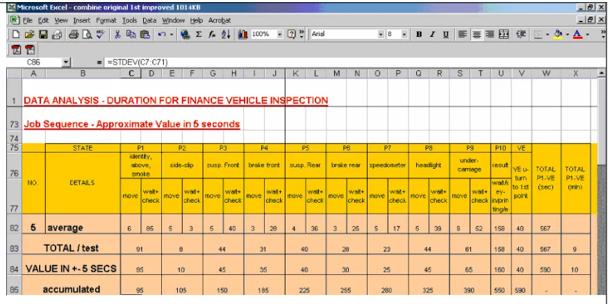
4.4 Data Experimental And Analysis 48
4.4.1 Point Average Summary 62
4.5 Data Simplifying– Approximates Value 64
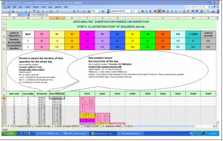
4.6 Data Sequence with Direct Point 66
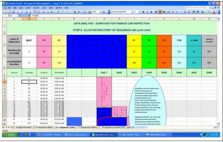
4.7 Data Sequence with Point Clash 68
4.8 Data Sequence with Waiting Time and without Point Clash
70
4.9 Data Sequence with Waiting Time and Adjustment 73
4.10 Results and Discussion 76
CHAPTER 5 SYSTEM ARCHITECTURE DESIGN
5.1 Introduction 79
5.3 User Requirements 80
5.3.1 Functional requirement 81
5.3.2 Non Functional Requirement 82
5.4 Process Designs 84
5.4.1 To-Be System Process 84
5.4.2 Conceptual Design 97
5.5 Physical Design 98
5.5.1 Database Design 98
5.5.2 Program Structure 100
5.5.3 Interface Chart 101
CHAPTER 6 HARDWARE & SOFTWARE REQUIREMENT
6.1 Introduction 102
6.2 Hardware Requirement 103
6.3 Software Requirement 103
6.4 Software Installation Guide 104
6.4.1 Installation of Java Development Kit 6 (JDK) Update 3
104
6.4.2 Eclipse Installation 110
6.4.3 Jboss Installation 112
6.4.3.1 Extract JBoss Application Server 112
6.4.3.2 Extract JBoss IDE 113
6.4.3.3 Extract Jboss Control Panel 1. 0 113
6.4.4 Server Database 115
6.4.4.1 MySQL Installation 115
CHAPTER 7 SYSTEM IMPLEMENTATION
7.1 Introduction 120
7.2 High Level Admin 120
7.2.1 Login 120
7.2.3 Submenu 1: Add New Centre 123
7.2.4 Menu 2: Centre Admin 124
7.2.5 Submenu1: Add New Centre Adm in 125
7.3 Managing Public Holidays 126
7.4 Constraint 127
7.4.1 Submenu 1: Add New Constraint 127
7.5 Booking Appointment 129
7.6 Inspection 130
7.6.1 Submenu 1: Inspection without Appointment ID and Special Case
133
7.7 Menu 7: Start and End Inspection 134
7.8 Menu 9: Searching 134
7.9 Menu 10: Booking Schedule 134
7.10Menu 11: Inspection Schedule 137
7.11Menu 12: Change Password 138
CHAPTER 8 DISCUSSION & CONCLUSION
8.1 Introduction 139
8.2 Achievements 141
8.3 Constraints 141
8.4 Challenges 142
8.5 Aspirations 142
LIST OF TABLE
TABLE NUMBER
TITLE PAGE
Table 2.1 Distributed Constraints Satisfaction (DisCS) Techniques
23
Table 3.1 Summary of RUP Phase 39
Table 4.1 Analysis for point inspection PI – Identification Check
49
Table 4.2 Analysis for point inspection P2 – Above Carriage Check
50
Table 4.3 Analysis for point inspection P3 – Emission Test 51 Table 4.4 Analysis for point inspection P4 – Side-Slip Test 52 Table 4.5 Analysis for point inspection P5 – Suspension Test 53 Table 4.6 Analysis for point inspection P6 – Brake Test 54 Table 4.7 Analysis for point inspection P7 – Speedometer 55 Table 4.8 Analysis for point inspection P8 – Headlight Test 56 Table 4.9 Analysis for point inspection P9 – Under Carriage
Check
57
Table 4.10 Analysis for point inspection P10 – Computerized Analysis
58
Table 4.11 Analysis for Vehicle Turning Back 59 Table 4.12 Analysis for Cumulative Time in Seconds 60 Table 4.13 Analysis for Cumulative Time in Minutes 61 Table 5.1 Clarification the Actor in Use Case 84
Table 6.1 A List of Hardware requirement 103
LIST OF FIGURES
FIGURE NUMBER TITLE PAGE
Figure 1.1 Layout of VIC JB 6
Figure 1.2 Sequence of Inspection Machines Located on Light Inspection Lane
6
Figure 1.3 General procedure for a finance car inspection 8 Figure 1.4 Number of Vehicles Scheduled in December 10 Figure 1.5 Number of Vehicles Scheduled in December
(after manual adjustment)
10
Figure 3.1 RUP methodology 34
Figure 4.1 Sample of Data Collection 46
Figure 4.2 Sample of datasets after filtering 47 Figure 4.3 Data analysis for each point of inspection 48 Figure 4.4 Data analysis for each point of inspec tion using
3-D Line Chart
49
Figure 4.5 Illustration of analysis for point inspection PI –
Identification Check using 3-D Column Chart.
50
Figure 4.6 Illustration of analysis for point inspection P2 –
Above Carriage Check using 3-D Column Chart.
51
Figure 4.7 Illustration of analysis for point inspection P3 –
Emission Test using 3-D Column Chart.
52
Figure 4.8 Illustration of analysis for point inspection P4 –
Side-Slip Test using 3-D Column Chart
53
Figure 4.9 Illustration of analysis for point inspection P5–
Suspension Test using 3-D Column Chart.
FIGURE NUMBER TITLE PAGE
Figure 4.10 Illustration of analysis for point inspection P6 –
Brake Test using 3-D Column Chart.
55
Figure 4.11 Illustration of analysis for point inspection P7 –
Speedometer using 3-D Column Chart
56
Figure 4.12 Illustration of analysis for point inspection P8 –
Headlight Test using 3-D Column Chart.
57
Figure 4.13 Illustration of analysis for point inspection P9 –
Under Carriage Test using 3-D Column Chart.
58
Figure 4.14 Illustration of analysis for point inspection P10
– Computerized Analysis using 3-D Column Chart.
59
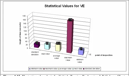
Figure 4.15 Illustration of analysis for Vehicle Turning Back using 3-D Column Chart
60
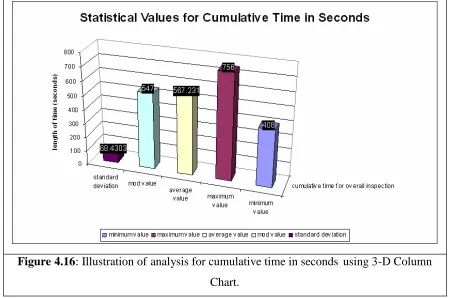
Figure 4.16 Illustration of analysis for cumulative time in seconds using 3-D Column Chart.
61
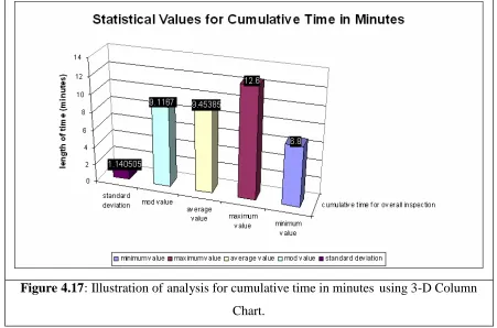
Figure 4.17 Illustration of analysis for cumulative time in minutes using 3-D Column Chart.
62
Figure 4.18 Point Average Summary 63
Figure 4.19 A Sample of Data with Approximate Value. 64 Figure 4.20 Approximate Values for each of point
inspection
65
Figure 4.21 Data Sequence with Direct Point 66
Figure 4.22 Point Sequence Analysis 68
Figure 4.23 Data sequence with point clash 69 Figure 4.24 Data Sequence with points clash in a 55
seconds time between two vehicle
69
Figure 4.25 Captured Screen of Header in Sequence Without Point Clash
FIGURE NUMBER TITLE PAGE
Figure 4.26 First Part in Sequence With Waiting Time Analysis.
71
Figure 4.27 Second Part in Sequence With Waiting Time Analysis
72
Figure 4.28 Changing the Header 74
Figure 4.29 First Part step with 4VE 75
Figure 4.30 Second Part step with 4Vehicle Examiner 76 Figure 4.31 The header for the with waiting time -3VE. 77 Figure 4.32 The header for the step with waiting time -5VE. 78
Figure 5.1 Use Case Diagram of Manual Process During Inspection Service
80
Figure 5.2 Use Case in ASRS System 85
Figure 5.3 Activity Diagram for Vehicle Registration Process
92
Figure 5.4 Sequence Diagram for Vehicle Registration Process
93
Figure 5.5 Sequence Diagram for Reservation of Appointment Process
94
Figure 5.6 Sequence Diagram for Insert New Event Process
95
Figure 5.7 Sequence Diagram of Update Table in Database 96 Figure 5.8 Conceptual Design for ASRS System 97
Figure 5.9 Physical Design of ASRS system 98
Figure 5.10 Class Diagram of ASRS System 99
Figure 5.11 ASRS Program Structure 100
Figure 6.1 Welcome Screen 104
Figure 6.2 License Agreement Screen 105
Figure 6.3 Custom Setup Screen 106
FIGURE NUMBER TITLE PAGE
Figure 6.5 Java Setup Screen 108
Figure 6.6 Complete Screen 109
Figure 6.7 Extract eclipse to location folder 110
Figure 6.8 Launch Eclipse 111
Figure 6.9 Select a workspace 111
Figure 6.10 First screen of Eclipse 111
Figure 6.11 Extract Jboss 112
Figure 6.12 Extract Jboss IDE 113
Figure 6.13 Extract Jboss Control Panel 1.0 113
Figure 6.14 Edit config.xml 114
Figure 6.15 Screen of JBoss Control Panel 1.0 114
Figure 6.16 Select The Setup Type 115
Figure 6.17 Ready to Install MySQL Se rver 116
Figure 6.18 Complete Screen 117
Figure 6.19 MySQL Server Instance Configuration 117
Figure 6.20 Modify Security Setting 118
Figure 6.21 Finish Screen 119
Figure 7.1 Login screen for high level admin 121 Figure 7.2 Source code for login funct ion 121
Figure 7.3 Menu Screen for super admin 122
Figure 7.4 Centre Menu for super admin 123
FIGURE NUMBER TITLE PAGE
Figure 7.9 Source code for menu: add new centre admin 126
Figure 7.10 Menu to add new Centre 127
Figure 7.11 Menu List of Constraints 128
Figure 7.12 Menu to add new Centre 129
Figure 7.13 Menu to Make New Booking 130
Figure 7.14 First part of the source code to make new appointment booking
131
Figure 7.15 Second part of the source code to make new appointment booking
132
Figure 7.16 Menu to add new Insp ection 132
Figure 7.17 Submenu to add new Special Inspection 133 Figure 7.18 Menu to Record Start Inspection 135 Figure 7.19 Menu to Record Finish Inspection 135
Figure 7.20 Menu for Searching 136
Figure 7.21 Menu to View Booking Schedule 136 Figure 7.22 Menu to View Inspection Schedule 137
ABBREVIATIONS
ASRS Appointment Scheduling for Reservation System RUP Rational Unified Process
LIST OF APPENDICES
APPENDIX TITLE
CHAPTER 1
INTRODUCTION
1.1 Introduction
Scheduling problem (that is assigning resources and time points to given tasks) arise in many real-world domains, for example reservation environment. A reservation
environment typically refers to a parallel -machine with n jobs available for processing. The processing time of each job has to fit within a given time window and with n jobs available for processing. The processing time of each job has to fit within a given time window and there may or may not be a ny slack. The time window of job is specified by a release date rj and a due date dj.
It may be the case that is not possible to process all n jobs, and the scheduler has to decide which jobs to process. Several objectives may be considered, for example, maximizing the number of job processed or maximizing the total amount of processing. Recently, several researchers have applied agent technology to such problems especially in manufacturing and business process control. Because of the widely spread lack of theoretically foundation for this kind of collaborative problem solving, the constraint satisfaction/optimization community has recently extended the theoretically well -founded constraint satisfaction problem (CSP) model to a distributed constraint satis faction
A distributed CSP is a constraint satisfaction problem in with variables and constraints are distributed among multiple agents. The variables are connected by constraints that define the constraints network among the agents.
As a result, the search algorithm for solving these problems is distributed algorithm. The algorithm is run by agents that communicate by sending and receiving messages. In general, messages contain information about assignments of values to variables and refutation of assignments, by agents that have no compatible assignments, to their own variables.
1.2 Research Objectives
The goal of this research is to develop appointment scheduling agent in reservation environment with implementation of Distributed Constrai nt Satisfaction (DisCS). In order to arrive this goal there are other objectives that need to be achieved, which are:
1. To develop applicable mathematical model based on Distributed Constraint Satisfaction (DisCS) in appointment schedule.
2. To design and develop system architecture of appointment scheduling agent.
1.3 Background of Case Study – Vehicle Inspection Centre
The number of vehicles undergoing inspection appears to be gradually increasing every year. The current workload based on 2004 statistics indica tes that the VIC performs 3.2 million commercial tests per year with 750,000 vehicles on the road. Within this statistic, VIC outstations in the rural areas service some 5%, a mobile station which covers three locations, services about 2% (i.e. around 900 – 1000 vehicles per month for each
location) and the rest are carried by VIC fixed centers. All the VIC’s branches have their
i. Wangsa Maju : 17, 091 vehicles inspected ii. Padang Jawa : 15, 613 vehicles inspected iii. Johor Bahru : 15, 306 vehicles inspected
The other VIC branches are Cheras, B.Maluri, Banting, Ipoh, Taiping, Teluk Intan, Mak Mandin, Teluk Kumbar, Sungai Petani, Alor Setar , Arau, Kuantan, Kota Bharu, Kuala Terengganu, Raub, Muar, Kluang, Alor Gajah, Seremban, Kota Kinabalu, Tawau, Sandakan, Kuching, Sibu, Miri, Labuan, Pelabuhan Klang, Kuala Krai and Kijal. Total inspections from all the centers for August 2004 is 177, 950 vehicles.
Generally, the inspection services offered at the VIC are as follows:
i. Initial Inspection : Inspection to determine vehicle status before registration with the Road Transport Department, or before transfer of ownership for commercial
vehicles.
ii. Routine Inspection : Routine half-yearly checks to gauge
roadworthiness of commercial vehicles and ensure compliance with Malaysia Construction and Use Rules 1959.
iii. Re-Inspection : To be conducted after a vehicle fails initial or routine inspection.
iv. Special Inspection : To determine roadworthiness of modified vehicles, as well as verification of imported vehicles.
v. Accident Inspection : In aid of police investigations of fatal accidents involving vehicles.
There are 10 points of vehicle inspection in the centre and it is defined as follow: i. Identification check – verifies the engine and chassis number of the
vehicle to be tested.
iii. Emission test– density of particles in diesel engines and volume of gases eg HC, CO etc in petrol engines are gauged through free acceleration tests. iv. Side-slip test– lateral movements of the vehicle are tested for optimum
road-handling criteria.
v. Suspension test– checks the effectiveness of the suspension system (springs, shock absorber, and joints) on each axle.
vi. Brake test– the various brake efficiencies, such as service brake
efficiency, dynamic unbalance, run -out, residual force and parking brake are evaluated for maximum performance.
vii. Speedometer– checks the road speed at the wheels against the value
indicated on the vehicle’s speedometer.
viii. Headlight test– measures the intensity and projection of the vehicle’s
headlights
ix. Undercarriage check – a vehicle’s undercarriage is thoroughly scrutinized for defects while it is tested on an axle play detector.
x. Computerized analysis – a state-of-the-art central computer controls and monitors each test phase. All relevant test data is then analyzed and the final result printed out.
1.3.1 Johor Bahru Vehicle Inspection Centre
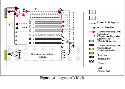
The size of the VIC premises is about 7.2 km2 (i.e. 120 metres X 60 metres) and is an open area. The layout of VIC JB is as in Figure 1.1. Queuing areas for light and heavy vehicles are located separately, except for initial inspections. The separation is to ease movement and for safety purposes. As an addition, separa te queuing areas for light and heavy vehicles are the reason of why the VIC has two entrances and one exit. Two entrances, each for light and heavy vehicle are designed at two different locations as shown in Figure 1.1, each of which located near its queue lane. This is to enable smooth flow for both types of vehicles.
For initial inspections, these two types of vehicles are combined in a single queue because initially they share the same equipment (i.e. weighing machine). Queuing areas for light and heavy vehicles at other VIC’s are usually adjacent to each other. There are
also two separate traffic wardens at each light and heavy queuing area. This shows that two numbering systems, exist for a different type of vehicle.
There are six inspection lanes wi th three light and three heavy lanes. Currently lanes 1 and 2 have been allocated for finance vehicles, lane 3 for light vehicles and lanes 4 -6 are for heavy vehicles.
Generally, the layout of a VIC affects its inspection flow. At VIC JB, as shown in Figure 1.1, we can see that there are four different flows, indicated by four different arrows. Each arrow represents a different type of inspection which flows through the system, throughout the inspection process. Private and accident inspections are loc ated separately from other inspections to speed up the inspection process.
Generally, the sequence of machines in an inspection lane in VIC JB is similar to other
one place. When a vehicle has completed its inspection, every driver will go to the printer to obtain the corresponding result.
Figure 1.1 : Layout of VIC JB
1.3.2 Domain Problem – Finance Car Inspection Lane
An inspection flow is different from an inspection procedure as it describes the activity that takes place on the day of inspection. The flow of inspection is slightly different from one VIC to another due to their unique physical layouts. Generally, upon arrival at a VIC, the vehicle owner or driver first shows the security guard related documents as proof of identification of his vehicle and himself. This allows him to enter the VIC premises. Only a vehicle with the correct appointment date and time is permitted to enter the VIC. This is to prevent the premises from becoming over crowded.
The vehicle owner then has to drive the vehicle to a specific queuing area, depending on the required type of inspection. He then has to obtain a queue number from a traffic warden. At the VIC, a numbering system is implemented as there are more than one inspection lane and a sequence of customers keep on coming.
While queuing and waiting to be inspected in the lane, vehicle owner makes a payment as his vehicle approaches the payment counter. When his number is called, his vehicle is passed on to a Vehicle Examiner who then takes the vehicle to the inspection lane and the inspection process starts. After inspection is completed, the result is printed and given to the vehicle owner. Actions regarding the result are then taken by the vehicle owner as described earlier. See Figure 1.3 for the general procedure in Finance Car Inspection Lane.
The constraints for finance company vehicles are: i. Number of lane considered is one. ii. No. of inspection considered is ten.
iii. Rule of inspection is that if all three major items passed, the result is pass. iv. Number of major item is three.
v. The three major items named chassis number, engine number and original body.
vii. Time stagger is one hour (but still not been used in this analysis). viii. Time slot is assumed as complete time with waiting time at initial bay.
ix. Complete time is assum ed as processing time with movement period and reserve time.
Figure 1.3: General procedure for a finance car inspection
x. Operation hour in this study is defined from 8 a.m. until 5 p.m.
xi. There is no tea break defined in this s tudy. It is based on the real operation at the time of data been collected.
xii. There is no lunch hour defined in this study. It is also based on the real operation at the time of data been collected.
xiii. Each vehicle must have a valid time slot of appointment to be inspected. But, if there was any vehicle that came at the wrong date and time, it was also been inspected.
Finance’s Inspection
VR1
(if three major items are passed, the result will be pass, otherwise.)
Rectification Work and come back for re-test
Finance company consideration (depends
on VR1)
- Automated reading of measurements - Computerized “pass-fail” decisions.
Pass
Fail
1.4 Vehicle Inspection Appointment Schedule
The date and time for a routine inspection is fixed by an appointment system. It is set during the previous routine inspection by a computerized vehicle appointment scheduling system. The system generates a specific inspection date and time for a particular vehicle.
A system known as “staggered system” has been applied at the VIC and has significantly
reduced congestion at the premises. The staggered system schedules the vehicles’ arrival
times on an hourly basis. Vehicles should arrive at the allotted times, otherwise they will not be allowed to enter the premises. However the system has been identified as possessing several weaknesses, such as being very rigid, and caters for routine inspections only.
The system does not take into account constraints like holidays. Figure 1.4 shows the number of vehicles, scheduled for inspection at VIC JB, each day in De cember 2004. The x axis represents the date and note that 1st is on Monday, 2nd is on Tuesday and so on. Sundays fell on 7th, 14th, 21st and 28th December. As noted in figure 6 there are vehicles which were scheduled for inspection on weekends.
To overcome this problem, manual adjustments are made by the Center Manager. Figure 1.5 shows the numbers of vehicles which have been re -scheduled via “manual adjustment”. From the figure, we can see that vehicles previously scheduled for a Sunday
0 1 0 0 2 0 0 3 0 0 4 0 0 5 0 0 6 0 0
1 2 3 4 5 6 7 8 9 1 0 1 1 1 2 1 3 1 4 1 5 1 6 1 7 1 8 1 9 2 0 2 1 2 2 2 3 2 4 2 5 2 6 2 7 2 8 2 9 3 0 3 1
D a t e i n D e c e m b e r
N u m b e r o f v e h ic le s
s c h e d u le d
Figure 1.4 : Number of Vehicles Scheduled in December
0 100 200 300 400 500 600 700
1 2 3 4 5 6 7 8 9 10 11 12 13 14 15 16 17 18 19 20 21 22 23 24 25 26 27 28 29 30 31
Date in December
n u m b e r o f v e h ic le s scheduled inspected
Another factor which makes the system rigid is that it does not consider th e maximum capacity of vehicles that can be inspected per hour. The present staggered system sets the next routine inspection time (which is scheduled for exactly six months after the issue of a pass certificate) for a particular vehicle, according to the vehicle’s current completion
time of inspection. The weaknesses of the vehicle scheduling system at the VIC have
some implications on the variability of daily demand, accuracy of vehicles’ inspection
schedule and workload planning.
Variability in daily demand is created by “manual adjustment” process and “drive-in” vehicles. “Manual adjustment” activity has largely caused the number of vehicles
scheduled on specific days to be shifted to the next working days. Hence, the number of vehicles to be inspected on that working day increases. This situation is worsened by
“drive-in” vehicles.
When a manual adjustment is done, the altered inspection schedule becomes packed. The situation is worsened by the arrival of drive -in vehicles which is quite high. A schedu le which continues to get packed will have smaller inter -arrival times. A smaller inter arrival compared to a constant service time would result in longer waiting times.
Apart from increasing waiting times, the weaknesses of the vehicle scheduling system at the VIC have resulted in difficulties of determine the actual workload for a specific vehicle examiner, to be done beforehand. This has disabled the planning of an effective
staff workload which finally creates a situation of “a fixed workforce handlin g variable
CHAPTER 2
LITERATURE REVIEW
2.1 Distributed Artificial Intelligence (DAI)
Distributed artificial intelligence (DAI) was a subfield of Artificial intelligence research dedicated to the development of distributed solutions for complex problems regarded as requiring intelligence. These days DAI has been largely supplanted by the field of Multi -Agent Systems. See the paper by Inman and Hewitt on some of the limitations of classic DAI.
Background
Main streams in DAI research i ncluded the following:
Parallel problem solving: mainly deals with how classic AI concepts can be modified, so that multiprocessor systems and clusters of computers can be used to speed up calculation.
Multi-Agent Based Simulation (MABS): a branch of DAI that builds the foundation for simulations that need to analyze not only phenomena at macro level but also at micro level, as it is in many social simulation scenarios.
2.2 Complexity of Constraints Satisfaction
The computational complexity of constraint satisfaction has mainly been studied for discriminating between tractable and intractable classes of constraint satisfaction problems on finite domains.
Solving a constraint satisfaction problem on a finite domain is an NP -complete problem in general. Research has shown a number of polynomial -time sub cases, mostly obtained by restricting either the allowed domains or constraints or the way constraints can be placed over the variables. Research has also established relationship of the constraint satisfaction problem with problems in other areas such as finite model theory and databases.
Overview
Establishing whether a constraint satisfaction problem on a finite domain has solutions is an NP complete problem in general. This is an easy consequence of a number of other NP complete problems being expressi ble as constraint satisfaction problems. Such other problems include propositional satisfiability and three -colorability.
Tractability can be obtained by considering specific classes of constraint satisfaction problems. As an example, if the domain is bina ry and all constraints are binary, establishing satisfiability is a polynomial -time problem because this problem is
One line of research used a correspondence between constraint satisfaction problem and the problem of establishing the existence of a homomorphism between two relational structures. This correspondence has been used to link constraint satisfaction with topics traditionally related to database theory.
A considered research problem is about the existence of dichotomies a mong sets of restrictions. This is the question of whether a set of restrictions contains only polynomial -time restrictions and NP -complete restrictions. This question is settled for some sets of restrictions, but still open for the set of all restrictions based on a fixed domain and set of relations, as of 2005. This is considered by some authors the most important open
question about the complexity of constraint satisfaction.
Restrictions
Tractable subcases of the general constraint satisfaction problems can be obtained by placing suitable restrictions on the problems. Various kinds of restrictions have been considered.
2.2.1 Structural and relational restrictions
Tractabiliy can be obtained by restricting the possible domains or constraints. In particular, two kinds of restrictions have been considered:
relational restrictions bounds the domain and the values satisfying the constraints;
structural restrictions bounds the way constraints are distributed over the variables.
This is instead done by structural restrictions. Structural restriction can be checked by looking only at the scopes of constraints (their variables), ignoring their relations (their set of satisfying values).
A constraint language is tractable if there exists a polynomial algorithm solving all problems based on the language, that is, using th e domain and relations specified in the domain. An example of a tractable constraint language is that of binary domains and binary constraints. Formally, this restriction corresponds to allowing only domains of size 2 and only constraints whose relation is a binary relation. While the second fact implies that the scopes of the constraints are binary, this is not a structural restriction because it does not forbid any constraint to be placed on an arbitrary pair of variables. Incidentally, the problem becomes NP complete if either restriction is lifted: binary constraints and ternary domains can express the graph coloring problem, while ternary constraints and binary domains can express 3 -SAT; these two problems are both NP -complete.
An example of a tractable class defined in terms of a structural restriction is that of binary acyclic problems. Given a constraint satisfaction problem with only binary constraints, its associated graph has a vertex for every variable and an edge for every constraint; two vertices are joined if they are in a constraint. If the graph of a problem is acyclic, the problem is called acyclic as well. The problem of satisfiability on the class of binary ayclic problem is tractable. This is a structural restriction because it does not pl ace any limit to the domain or to the specific values that satisfy a constraints; rather, it restricts the way constraints are placed over variables.
2.2.2 Uniform and non-uniform restrictions
The subcase obtained by restrictin g to a finite constraint language is called a non-uniform problem. These problems are mostly considered when expressing constraint satisfaction in terms of the homomorphism problem, as explained below. Uniform problems were also defined in the settings of homomorphism problems; a uniform problem can be defined as the union of a (possibly infinite) collection of non -uniform problems. A uniform problem made of an infinite set of non -uniform problems can be intractable even if all these non-uniform problems are tractable.
2.2.3 Tree-based restrictions
Some considered restrictions are based on the tractability of the constraint satisfaction problem where the constraints are all binary and form a tree over the variables. This is a structural restriction, as it c an be checked by looking only at the scopes of the constraints, ignoring domains and relations.
This restriction is based on primal graph of the problem, which is a graph whose vertices are the variables of the problem and the edges represent the presence of a constraint between two variables. Tractability can however also be obtained by placing the condition of being a tree to the primal graph of problems that are reformulations of the original one.
Equivalence conditions
2.3 Constraints satisfaction and the homomorphism problem
A link between constraint sa tisfaction and database theory has been provided in the form of a correspondence between the problems of constraint satisfiability to the problem of checking whether there exists a homomorphism between two relational structures. A relational structure is a mathematical representation of a database: it is a set of values and a set of relations over these values. Formally, A
V,R1A,...,RnA
, where each RiAis a relation over V, that is, a set of tuples of values of V.A relational structure is different from a constraint satisfaction problem because a constraint is a relation and a tuple of variables. Also different is the way in which they are used: for a constraint satisfaction problem, finding a satisfying assignment is the main problem; for a relation structure, the main problem is finding the answer to a query. The constraint satisfaction problem is however related to the problem of establishing the existence of a homomorphism between two relational structures. A homomorphism is a function from the values of the first relation to the values of the second that, when applied to all values of a relation of the first structure, turns it into a subset of the corresponding relation of the second structure. Formally, h is a homomorphism from
A
n A
R R
V
A , 1 ,..., to
B n B R R D
B , 1 ,..., if it is a function from V to D such that, if
Ai
k R
x
x1,..., then
B i k R x h x
h 1 ,..., .
A direct correspondence between the constraint satisfaction problem and the
The inverse correspondence is the opposite one: given two relational structures, one encodes the values of the first in the variables of a constraint satisfaction problem, and the values of the second in the domain of the same p roblem. For every tuple of every relation of the first structure, there is a constraint having as values the correspondent relation of the first structure. This way, a homomorphism corresponds to mapping every scope of every constraint (every tuple of ever y relation of the first structure) into a tuple in the relation of the constraint (a tuple in the corresponding relation of the second structure).
A non-uniform constraint satisfaction problem is a restriction where the second structure of the homomorphism problem is fixed. In other words, every relational structure defines a non-uniform problem, that of telling whether a relation structure is homomorphic to it. A similar restriction can be placed on the first structure; for any fixed first structure, the homomorphism problem is tractable. A uniform constraint satisfaction problem is an arbitrary restriction to the sets of structures for the first and second structure of the homomorphism problem.
2.3.1 Conjunctive query evaluation and containment
Since the homomorphism problem is equivalent to conjunctive query evaluation and conjunctive query containment, these problems below are equivalent to constraint satisfaction as well.
i) Join evaluation
Dichotomy theorems
Some constraint languages (or non -uniform problems) are known to be polynomial -time, and some others are known to be NP-complete. However, it is possible that some
constraint languages are neither. It is indeed known by Ladner's theorem that, if P is not equal to NP, there exists problems in NP that are neither polynomial -time nor NP-hard. As of 2006, it is not known if such problems include a constraint language. If this is not the case, the set of all constraint languages could be divided exactly in the set of
polynomial-time and NP-complete problems, that is, this set has a dichotomy.
Some partial results are however known for some sets of constraint languages. The most known such result is Schaefer's dichotomy theorem, which proves the existence of a dichotomy in the set of constraint languages on a binary domain. More precisely, it proves that a relation restriction on a binary domain is tractable if all its relations belong to one of six classes, and is NP -complete otherwise. Bulatov proved a dichotomy theorem for domains of three elements.
Another dichotomy theorem for a subset of the constraint lan guages is the Hell-Nesetril theorem, which shows a dichotomy for problems on binary constraints having all the same fixed symmetric relation. In terms of the homomorphism problem, every such problem is equivalent to the existence of an homomorphism from a relational structure to a given fixed undirected graph (an undirected graph is a relational structure with a single binary symmetric relation). The Hell -Nesetril theorem proves that every such problem is either polynomial-time or NP-complete. More precisel y, the problem is polynomial -time if the graph is 2-colorable, that is, it is bipartite, and is NP -complete otherwise.
Sufficient conditions for tractability
gives a truth value to a set of literals over a given alphabet, each literal being an
expression of the form L
a1,...,an
; as a result, a Boolean Datalog query expresses aset of sets of literals, as it can be considered semantically equivalent to the set of all sets of literals that it evaluates to true.
On the other hand, a non -uniform problem can be seen as a way for expressing a similar set. For a given non-uniform problem, the set of relations that can be used in constraints is fixed; as a result, one can give unique names R ,...,1 Rn to them. An instance of this non-uniform problem can be then written as a set of literals of the form Ri
x1,....,xn
.Among these instances/sets of literals, some are satisfiable and some are not; whether a set of literals is satisfiable depends on the relations, which are specified by the non-uniform problem. In the other way around, a non -non-uniform problem tells which sets of literals represent satisfiable instances and which ones represent unsatisfiable instances. Once relations are named, a non -uniform problem expresses a set of set s of literals: those associated to satisfiable (or unsatisfiable) instances.
A sufficient condition of tractability is that a non -uniform problem is tractable if the set of its unsatisfiable instances can be expressed by a Boolean Datalog query. In other words, if the set of sets of literals that represent unsatisfiable instances of the non -uniform problem is also the set of sets of literals that satisfy a Boolean Datalog query, then the non-uniform problem is tractable.
ii) Local consistency
The following conditions exploit the primal graph of the problem, which has a vertex for each variable and an edge between two nodes if the corresponding variables are in a constraint. The following are conditions on binary constraint satisfaction problems where enforcing local consistency is tractable and allows establishing satisfiability:
1. enforcing arc consistency, if the primal graph is acyclic
2. enforcing directional arc consistency for an ordering of the variables that makes the ordered graph of constraint having w idth 1 (such an ordering exists if and only if the primal graph is a tree, but not all orderi ngs of a tree generate width 1) 3. enforcing strong directional path consistency for an ordering of the variables that
makes the primal graph having induced width 2.
A condition that extends the last one holds for non -binary constraint satisfaction problems. Namely, for all problems for which there exists an ordering that makes the primal graph having induced width bounded by a constant i, enforcing strong directional i-consistency is tractable and allows establishing satisfiability.
iii) Tree-based conditions
Constraint satisfaction problems composed of binary constraints only can be viewed as graphs, where the vertices are variables and the edges represent the presen ce of a
constraint between two variables. This graph is called the Gaifman graph or primal graph of the problem.
This property of tree-like constraint satisfaction problems is exploited by decomposition methods, which convert problems into equivalent ones that only contain binary
constraints arranged as a tree. The variables of these problems corres pond to sets of variables of the original problem; the domain of such a variable is obtained by
considering some of the constraints of the original problem whose scope is contained in the corresponding original set of variables; constraints of these new pr oblems represent equality of variables that are contained in two sets.
If the graph of one such equivalent problem is a tree, the problem can be solved efficiently. On the other hand, producing one such equivalent problem may be not be efficient because of two factors: the need to determine the combined effects of a group of constraints over a set of variables, and the need to store all tuples of values that satisfy a given group of constraints.
Necessary condition for tractability
A necessary condition fo r the tractability of a constraint language based on the universal gadget has been proved. The universal gadget is a particular constraint satisfaction problem that was initially defined for the sake of expressing new relations by projection.
2.4 Distributed Constraints Satisfaction Problem (DisCSP)
DisCSP is a framework for describing a problem in terms of constraints that are known and enforced by distinct participants (agents). The framework was used under different
The currently most well known paper is the one which introduced in 1992 as asynchronous complete algorithm for solving such problems is Asynchronous
backtracking (ABT). A large number of such techniques are now available, See Table 2.1 below.
Year Technique Abbreviation Characteristics
1992 Asynchronous Backtracking ABT Static ordering, complete search
1994 Asynchronous Weak-Commitment
AWC Reordering, fast, complete search
1995 Distributed Breakout Algorithm
DBA Incomplete but fast
2000 Distributed Forward Chaining DFC Slow, comparable to ABT 2000 Asynchronous Aggregation
Search
AAS Aggregation of values in ABT
2001 Maintaining Asynchronously Consistencies
DMAC The fastest algorithm
2001 Asynchronous Backtracking with Reordering
ABTR Reordering in ABT with bounded nogoods 2002 Secure Computation with
Semi-Trusted Servers
- Security increases with the number of trustworthy servers
2003 Secure Multiparty Computation for Solving DisCSPs
MPC- DisCSP1- MPC-DisCSP4
Secure if half (½) of the participants are trustworthy.
2.5 Agent Technology
What is Agent
Agent is anyone who acts on behalf or in the interest of somebody else. So most agent are designed to act as or for the user to help execute some task or operation. Agents come in various form for various purpose. Here, an agent can be a human being, a robot, or a computer program. Consequently, a more precise and very general definition can be provided for agents is it can do routine work for users or assist them with complicated and finished their tasks.
In the internet definition, it defines that an agent (also called an intelligent agent and sometime called a bot) is a program that gathers information or performs some other service without your immediate presence and on some standard schedule. Typically, an agent is an entity that is able to carry out some task usually to help human user. Agent can be biologic, robotic or computational. In general we can describe the agent as referring to a component of software or hardware which is able of acting in order to accomplish tasks on behalf of its user.
Software Agent
A software agent is a computer program (more to software) that can accept tasks from its human user can figure out which actions to perform in order to solve these tasks and can actually perform these task actions without user aided.
2.5.1 Agent Properties
The behavior of the agent must have at least the following properties:
-Autonomy: Agent can operate on their own without the need for human guidance
with its environment, the processes performed by an agent are in full control of the agent itself.
Reactivity: leading the agent to rapidly respond to new information perceived
from its environment. Reactivit y indicates that the agent will respond to perceived changes in the environment and able to handle changing environment.
Proactively: agents should not simply act in response to their environment; they
should be able to exhibit opportunistic, goal -directed behavior and take their initiative where appropriate. In situation where the environment changes or the goal achievement fails, the agent will still to find way to reach the goal
Learning: React and interact with their external environment, from observ ation or
by user’s instructions.
Flexible: Agents have flexible behavior, because they can achieve in several
ways. To reach a goal an agent chooses a plan to follow. If the plan fails, the agent can choose between other possibilities to obtain the desire d result.
Social ability / Cooperation: is the central property in multi-agent systems.
Agents must be able to communicate and cooperate with other agents and humans to complete their own problem solving and help others with their activities. It also called as cooperation, which is the ability to interact with other agent, cooperate with each others and interaction with possible human via some communication language.
Other non-mandatory properties of agents include adaptability, mobility, and intelligence. Although the term software agent is sometimes used as a synonym for
computer providing resources via suitable network links are considered more fundamental than any form of intelligence.
2.5.2 How they applied this technology in a system
Agents propose new possibilities and solution to answer the problem suitable to their properties and characteristics. Some of the characteristic of agent is know the preferences of their user. The efficiency of the scheduling process used and the quality of the schedule generated, then affects the working of an organization to a large extends. The used of agent can developed more efficient schedule because it can save time and effort on the part of human. There is also a communication between agent and user. The age nts manage the scheduling process on behalf the individual user, without human interaction. Each agent can access to calendar and preference information of its user.
Generally, agent has initial information about schedule the meeting. That means, the agents have to learn and get to know the habit and preference of user by observing the action of the user. Some of the actions are marking suggestion, collecting or receive feedback either positive or negative and the last is suggestion from the other user. So from this way, the user comes to trust the agent and decide to delegate their meeting scheduling decision. In this approach, agent also provide autonomous scheduling capabilities between intelligent agent, where these agent use knowledge about the priorities of people to perform their task such as automatically screening, directing and even responding to information.
The meeting to be schedule must have a day, a start time and place, and the problem is solve when all agent reach an agreement on values fo r these attributes. Agents negotiate by having one agent propose a meeting. The agent who initiates the new meeting called as host agent. While the meeting is start, the other attendee or invitee agent have ability to make decision on behalf of their user to respond the invitation by accepting or rejecting
group of agent such as in their activity and monitoring for any change in the schedule. Then agent predicts a response and negotiates with other agent to suggest an optimal time for the meeting.
2.6 Intelligent Agent
The terms "agent" and "intelligent agent" are ambiguous and have been used in two different, but related senses, which are often confused.
In computer science, an intelligent agent (IA) is a software agent that assists users and will act on their behalf, in performing non -repetitive computer-related tasks. An agent in the sense of the word is like an insurance agent or travel agent. While the working of software agents used for operator assistance or data mining (sometimes referred to as bots) is often based on fixed pre -programmed rules, "intelligent" in this context is often taken to imply the ability to adapt and learn.
In artificial intelligence, the sa me term is used for intelligent actors, which observe and act upon an environment, to distinguish them from intelligent thinkers isolated from the world. An agent in this sense of the word is an entity that is capable of perception and action. Such an agent might be a robot or an embedded real time software system - and is intelligent if it interacts with its environment in a manner that would normally be
regarded as intelligent if that interaction were carried out by a human being.
There is no reason why t hese two notions of intelligent agent need to be related. An intelligent agent in the first sense might be implemented using conventional software techniques and display no more intelligence than a conventional computer program. On the other hand, an intelligent agent in the second sense might be wholly autonomous, carrying out its own agenda, and acting as an agent for no one.
1. Physical Agents - A physical agent is an entity which percepts through sensors and acts through actuators.
2. Temporal Agents - A temporal agent may use time based stored information to offer instructions or data acts to a computer program or human being and takes program inputs percepts to adjust its next behaviors.
A simple agent program can be defined mathematically as an agent function which maps every possible percepts sequence to a possible action the agent can perform or to a coefficient, feedback element, function or c onstant that affects eventual actions:
f:P *− >A
The program agent, instead, maps every possible percept to an action.
It is possible to group agents into five classes based on their degree of perceived intelligence and capability:
1. simple reflex agents; 2. model-based reflex agents; 3. goal-based agents;
4. utility-based agents; 5. learning agents. 1. Simple reflex agents
Simple reflex agents act only on the basis of the current percept. The agent function is based on the condition-action rule:
if condition then action rule
2. Model-based reflex agents
Model-based agents can handle partially observable environments. Its current state is stored inside the agent maintaining some kind of structure which describes the part of the world which cannot be seen. This behavior requires information on how the world
behaves and works. This additional information completes the “World View” model.
3. Goal-based agents
Goal-based agents are model-based agents which store information regarding situations those are desirable. This allows the agent a way to choo se among multiple possibilities, selecting the one which reaches a goal state.
4. Utility-based agents
Goal-based agents only distinguish between goal states and non -goal states. It is possible to define a measure of how desirable a particular state is. Th is measure can be obtained through the use of a utility function which maps a state to a measure of the utility of the state.
5. Learning agents
In some literature IAs are also referred to as autonomous intelligent agents , which mean they act independently, and will learn and adapt to changing circumstances. IA systems should exhibit the following characteristics:
learn and improve through interaction with the environment (embodiment)
adapt online and in real time
learn quickly from large amounts of data
accommodate new problem solving rules incrementally
have memory based exemplar storage and retrieval capacities
have parameters to represent short and long term memory, age, forgetting, etc.
To actively perform their functions, Intelligent Agents today are normally gathered in a
hierarchical structure containing many “sub-agents”. Intelligent sub-agents process and perform lower level functions. Taken together, the intelligent agent and sub -agents create a compete system that can accomplish difficult tasks or goals with behaviors and
responses that display a form of intelligence.
Some of the sub-agents (not already mentioned in this treatment) that may be a part of an Intelligent Agent or a com plete Intelligent Agent in them are:
1. Temporal Agents (for time -based decisions);
2. Spatial Agents (that relate to the physical real -world);
3. Input Agents (that process and make sense of sensor inputs - example neural network based agents neural network);
4. Processing Agents (that solve a problem like speech recognition); 5. Decision Agents (that are geared to decision making);
6. Learning Agents (for building up the data structures and database of other Intelligent agents);
7. World Agents (that incorporate a combination of all the other classes of agents to allow autonomous behaviors).
A very limited set of agents, that might be classified as semi -intelligent due to their lack of complexity, decision making, extremely limited world view and learning capacity can be found in the reference: Third Canadian Edition of "Management Information Systems for the Information Age" . This document suggests that there are only four essential types of Intelligent Agents:
1. Buyer agents or shopping bots 2. User or personal agents
Buyer Agent
Buyer agents travel around a network (i.e. the internet) retrieving information about goods and services. These agents, also known as 'shopping bots', work very efficiently for commodity products such as CDs, books, electronic components, and other one -size-fits-all products. Amazon.com is a good example of a shopping bot. The website will offer you a list of books that you might like to buy on the basis of what you're buying now and what you have bought in the past.
User or Personal Agents
User agents, or personal agents, are intelligent agents that take action on your behalf. In this category belong those intelligent agents that already perform, or will shortly perform, the following tasks:
Check your e-mail, sort it according to priority (your priority), and alert you when good stuff comes through - like college acceptance letters
Play computer games as your opponent or patrol game areas for you
Assemble customized news reports for you. There are sev eral versions of these, CNN being a prime example
Find information for you on the subject of your choice
Fill out forms on the Web automatically for you, storing your information for future reference
Scan Web pages looking for and highlighting text that co nstitutes the "important" part of the information there
Monitoring and Surveillance Agents
These agents, also known as "predictive agents", are intelligent agents that observe and report on equipment. For example, NASA's Jet Propulsion Laboratory has an agent that monitors inventory, planning, and scheduling equipment ordering to keep costs down, as well as food storage facilities. These agents usually monitor complex computer networks that can keep track of the configuration of each computer connected to the network.
Data Mining Agents
A data mining agent operates in a data warehouse discovering information. A 'data
CHAPTER 3
METHODOLOGY
3.1 Introduction
Some organization especially in safety -critical area requires that certain methodologies be used as it increases the quality of their software and also offer a certain degree of legal protection to all parties involve. Metho dology helps to manage with the complexity of the software development process. Methodology may provide a framework for application of technique and resources at appropriate times during the development process. According to Bernard a good software methodology is a methodology which:
-This chapter emphasizes on system development process which focuses on project methodology, a brief explanation on Unified Modeling Language as a technique for design the functionality of system and the end of this sectio n this chapter will be concluded by the summary. In this area the RUP methodology has been used as a technique and guidelines for software development process. There are including the workflow on RUP and also elaborate in detail on their phase such as ince ption, elaboration, construction and testing phase .
“can be describes qualitatively, as well as qualitatively , can be used
repeatedly, each time achieving similar results, can be taught to others within a reasonable timeframe, can be applied by others with a reasonable
3.2 Software Development Process
A software development process is describing software life cycle and software process. It begins with architecture, moves through analysis, design, and implementation, undergoes testing and finally is delivered to user. It also covers how to develop the software in the best way, a guideline and manner to develop the best quality of product by variety of tasks or activities for each phase in project methodology.
There are various difference software development methodologies available for modeling software system. The Rational Unified Process (RUP) has been selected in this project methodology. The choice of RUP methodology for a software development process because this technique is the best practice that can be tailored with large and suitable for all range of project and it aimed at meeting the needs of end users. RUP is an Object Oriented framework which provides guidelines and templates and tools to support software d evelopment process.
Figures 3.1: RUP methodology
1. Business modeling
Understanding the structure and operation of the business How the product fits into their organization
2. Requirements
Understand what user need from a product and to define these needs is a way that can be
the basis for designing and planning product’s content.
3. Analysis and design
Translate requirement into a design for the system 4. Implementation
Construct a working version of the system. 5. Test
Verify that the system meets requirement and minimize errors 6. Deployment
Distribute the product to users.
The Benefits of RUP
RUP provides the system development team with the advantages of RUP best practice s while providing a framework for addressing overall system issues. Some of the benefits of RUP include:
- Provides for ongoing collaboration among business analysts, architects, system engineers, software developers, hardware developers, and testers.
- Provides views that enable teams to address system quality issues in an architecture -driven process.
- Provides UML support for systems architecture. - Scales upward to very large systems.
- Provides workflows for determining hardware and software components.
- Easy to understand and facilitate resource planning and work structuring
- RUP delivers a well-structured framework, divided into phase and workflow, allowing easy navigation within the framework
Phases in RUP Methodology
According to RUP methodology, the phase in RUP had been applied as a guideline to accomplish the development of new reservation scheduling system. Following of that, the detail of description about each p hase in RUP methodology and some related works that have been done show as below:
-Inception Phase
Inception phase aimed to establish a business case. In general, the problem is first defined and analysis of the requirement of the system will be identifi ed by discussion with the user. Included in this phase, the title was proposed, the background of problem in case study has been studied. The scope and objectives for development of this Appointment Scheduling for Reservation System (ASRS) system had been determined and clearly stated. This phase is very important to identify the business needs from the system and also to get the business value from the proposed system.
Elaboration Phase
Elaboration is the initial series of iteration which the team does serious investigation, implements the program, build the system architectures, analysis the user requirement specification and find out some high -risk issues.
During elaboration phase, the architecture of new system will be design. In this phase the real data for processing time in each process of vehicle inspection was collected. Data collection had been carried in vehicle inspection center. The processing time was recorded in seconds due to precision. From data collection, the data analysis is initiated by extracting data int o the algorithm. Data analyses is some of steps for transforming data with the aim to generate some algorithm that will serve as an engine to this new system to solve time constraint problem.
Beside of that, the functional requirement was defined request ed by user for new reservation scheduling system. The user requirements have been described in Software Requirement Specification (SRS) document. In this document, that is not only cover on user requirement but also the explanation about the performance, r eliability, security, maintainability and other critical issues. Finally, the initial design and architecture modeling will be generated using UML design for the proposed system development. The preliminary designs have been developed including use case di agram, class diagram, sequence diagram and activity diagram.
Construction Phase
A coding design may be the most obvious and difficult part on development of system. The system will de coded by programming language. In this process, Java programming lan guage has been selected as a programming language to build ASRS system. During this phase, the unit testing must be conducted together to make sure the functionality of module process was
Transition Phase
After the code is appropriately tested and approved, it is moved into transition phase to ensure the software is available to end user. This phase includes final testing of product and making some minor adjustment based on error feedback. As a part o f this phase, the application will be tested to end user and they will evaluate the quality of system. It is very important to have training classes for most users to build excitement into adopting the new system. At the end of this phase is documenting th e internal design of software for the purpose of future maintenance and enhancement. Documentation is important as a user guideline to use the new system. The several project documents were produced such as user manual, a plan to support the user and a plan for upgrading the information system in the future. Then all requirement of the system will be installed and the related document will be delivered to end user.
3.3 Software Development Tools
The well-known Unified Modeling Language (UML) has been c hosen as tools for software development. The UML is a very important part of developing objects oriented software and the software development process. The UML represent a collection of best engineering practices that have proven successful in the modeling of large and complex system. The UML can help even non-programmer to understanding the overall functionality of the system in a way that meets the entire requirement in the system. The modeling design patterns with UML have several advantages include:
-- It quite naturally to object oriented modeling
- Process models can be communicated more easily in a large number of people
- UML provide a large set of diagram which can be used to define both structured and behavior of dynamic software process