20th International Conference on Structural Mechanics in Reactor Technology (SMiRT 20) Espoo, Finland, August 9-14, 2009 SMiRT 20-Division 3, Paper 2045
An Implicit Solution Framework for Reactor Fuel Performance Simulation
Glen Hansen, Chris Newman, Derek Gaston, and Cody Permann
Multiphysics Methods Group, Idaho National Laboratory, Idaho Falls, Idaho, USA e-mail: [email protected]
Keywords: reactor multiphysics, nuclear fuel performance, fuel thermomechanics.
1
ABSTRACT
The simulation of nuclear reactor fuel performance involves complex thermomechanical processes between fuel pellets, made of fissile material, and the protective cladding that surrounds the pellets. An important design goal for a fuel is to maximize the life of the cladding thereby allowing the fuel to remain in the reactor for a longer period of time to achieve higher degrees of burnup. This paper presents an initial approach for modeling the thermomechanical response of reactor fuel, and details of the solution method employed within INL's fuel performance code, BISON.
The code employs advanced methods for solving coupled partial differential equation systems that describe multidimensional fuel thermomechanics, heat generation, and oxygen transport within the fuel. This discussion explores the effectiveness of a JFNK-based solution of a problem involving three dimensional fully coupled nonlinear transient heat conduction and that includes pellet displacement and oxygen diffusion effects. These equations are closed using empirical data that is a function of temperature, density, and oxygen hyperstoichiometry. The method appears quite effective for the fuel pellet / cladding configurations examined, with excellent nonlinear convergence properties exhibited on the combined system. In closing, fully coupled solutions of three dimensional thermomechanics coupled with oxygen diffusion appear quite attractive using the JFNK approach described here, at least for configurations similar to those examined in this report.
2
INTRODUCTION
BISON is built upon a code framework based on tight coupling of two and three dimensional fuel physics models that employ physics-based preconditioned Jacobian-free Newton-Krylov solution methods using modern software engineering principles. Goals of the code are to perform higher fidelity calculation of two and three dimensional pellet cladding mechanical interaction and to support advanced models to provide a parallel analysis and design capability.
Significant progress has been achieved toward developing a fully-coupled solution methodology for thermomechanics coupled to oxygen diffusion and in creating a base multidimensional thermomechanics code that employs these solution methods on UO2 fuel pellet geometries. BISON is being developed using modern software engineering principles resulting in a code that is inexpensive to maintain as well as meeting software quality goals. This study illustrates the efficacy of this approach for three-dimensional parallel thermomechanics coupled with oxygen diffusion run on up to 1024 processors.
3
THEORETICAL BACKGROUND
where T, ρ, Cp and k are temperature, density, specific heat and thermal conductivity. Here, ΓN denotes the top and bottom boundary of the fuel pellet and ΓD denotes the outer circumferential fuel pellet boundary. The model for oxygen diffusion s is given by
where D is the diffusivity of UO2, F is the thermodynamic factor of oxygen, Q* is the heat of transport of oxygen and R is the universal gas constant. The solid mechanics model for the displacement u is given by
with
and
The coefficients E and ν are Young’s modulus and Poisson’s ratio. The forcing term f weakly enforces thermal expansion, and γD denotes the pellet bottom. The quantities Q, ρ, Cp, k, D, Q*, F and E in the above and the constitutive models in f are given by nonlinear empirical functions of T, s and u. These constitutive and closure relations are from Ramirez et. al. (2006) and Hohorst (1990) (see Newman et. al. 2009 for specific details).
This system of equations is discretized using a standard finite element method, using the approach advanced by Newman et. al. (2009). In this approach, the resulting nonlinear algebraic system is expressed in the form
that is of length N unknowns. This system is then solved using a Jacobian-free Newton Krylov method (see Knoll and Keyes (2004) and references contained therein). If one applies Newton’s method to the above, a linear system results
where J is the Jacobian of the system and k is the iteration counter for the Newton iteration. It is usually necessary to solve the preconditioned form of this system in engineering applications,
.
When a Krylov method such as GMRES (Saad (1995)) is used to solve the linear system, it is not necessary to compute or store the Jacobian of the system, as only the action of the Jacobian on a vector is needed to solve the linear problem. The action may be approximated using a finite difference approximation,
and hence this solution method is named a Jacobian-free Newton Krylov (JFNK) method. Effective preconditioning must typically be used for efficiency. These results employ a physics-based preconditioner based a lower triangular approximate system
by solving
where q represents the action of M-1 on v (e.g. approximately solving Mq = v). Alternatively, one may employ a diagonal decoupled preconditioner
Figure 1. Number of linear iterations (effort) needed to achieve a given level of accuracy using various preconditioning choices on a coupled thermomechanics problem.
Figure 1 shows a representative calculation on a thermomechanics problem of the performance of various preconditioners applied in a JFNK solution framework. The red curve is unpreconditioned and the green curve shows the performance of a diagonal block preconditioned approach. While the diagonal
preconditioner is very simple and a rather poor approximation of the problem being solved (all the coupling terms are missing), it is still significantly better than no preconditioner at all. The blue curve shows a lower-triangular preconditioner, and the pink curve is a lower lower-triangular preconditioner using two block Gauss-Seidel sweeps to provide an approximate inverse. Note that each preconditioner requires more effort to form and invert, but this extra effort pays off in fewer GMRES iterations needed to solve the linear system.
4
BENCHMARK RESULTS
transient response of the system and the dynamical time step chosen to resolve the coupled multiphysics problem. The timestepping algorithm is a variation of that proposed by Pope et. al. (2007).
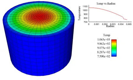
Figure 2. Steady state gap / cladding system simulation, using the approach advanced by Newman (2009) and the correlations presented therein. The temperature profile matches the results shown in the paper and also those presented in Ramirez (2006).
Figure 3. Results of transient calculation. Figure (a) shows transient response for reactor start up from ambient conditions for comparison with Figure 6 in Ramirez (2006) (and using Q&(t) given in that paper). In these results, so = 0.01. Figure (b) shows the timestep history of the transient calculation.
5
PELLET / CLADDING COUPLED SIMULATION
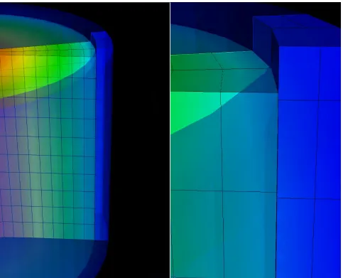
(decreasing the thermal resistance across the gap). In time, the pellet outer surface touches the inner surface of the cladding and begins to displace the cladding outward. Figure 4 shows a three dimensional mesh of a calculation at the point where the top ridge of the pellet is just touching the cladding. The boundary condition of zero axial displacement is applied at the bottom of the pellet and at the bottom of the cladding segment shown in the picture. Further, the meshes initially match between the pellet and cladding, axially. At the time that the pellet swells to contact the cladding, note that significant axial displacement of the top of the pellet has occurred relative to the cladding.
Figure 4. Representative calculation of a coupled thermomechanical calculation of a pellet / cladding system, at the point where the pellet is just beginning to touch the cladding. Left image shows a translucent view, with color indicating temperature. Right view is a closeup view of the top rim of the pellet.
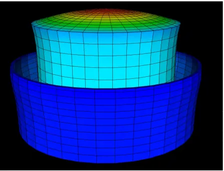
Figure 5. Exaggerated displacement of the pellet and cladding shown in Figure 4. The displacement of the cladding is exaggerated by a factor of 1000 to show the “bambooing” of the cladding caused by the contact of the pellet. Pellet deformation is exaggerated by 100 and offset to show the outside profile of the pellet. Color indicates relative temperature.
6
MULTISCALE MULTIPHYSICS SIMULATION
One fundamental limitation of the preceding finite element based simulation capability is the use of
correlations and experimentally-derived data to close the partial differential equation models used in BISON. While light water reactor fuel data is quite plentiful and routinely used for this purpose, data applicable to extended burnup situations is harder to come by. Further, to design new fuels and new fuel geometry, existing data may not be fully appropriate. It would be advantageous to develop the capability to link “engineering scale” fuel performance codes like BISON to mesoscale (and below) simulation tools capable of calculating the fundamental behaviour of the fuel and cladding at these smaller scales to close the engineering scale finite element problem. Secondly, it is not generally practical to perform a pellet, or multiple pellet, calculation using a mesoscale code alone. The amount of computing power necessary to do so is not generally available.
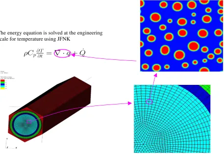
Figure 6. Multiscale multiphysics coupling schematic for calculation of thermal conductivity using
a mesoscale phase-field simulation. The phase-field calculation uses the approach advanced by
Rokkam et. al. (2008).
First, an engineering scale calculation is performed using an assumed thermal conductivity
k
or a
value from the best available correlation. The strategic locations within the engineering scale are
then chosen, for example those Gauss points with the highest temperature. At each of these Gauss
points, a mesoscale calculation is initiated that is passed the temperature at the location. Many
phase field calculations, perhaps similar to that proposed by Rokkam (2008), are performed in
parallel; one per chosen Gauss point. A thermal conductivity is calculated at the mesoscale, and
then upscaled to the engineering scale calculation. This new thermal conductivity is employed for
an updated engineering scale solution. This process must be repeated until convergence is achieved
given this explicit example. However, note that this example just described a coupled multiphysics
problem; it can also be solved in a fully coupled manner simultaneously with the engineering scale
problem using JFNK.
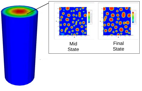
Figure 7 shows the results of a fully-coupled phase field / engineering scale solution solved with
JFNK within BISON. The mesoscale results are shown at a single Gauss point; note the evolution
of the voids within the phase field result over time. This coupled JFNK solution has proven quite
effective and is quite scalable on a parallel computer as described. Left for future work is a more
sophisticated strategy for determining which Gauss points should host the mesoscale solution(s).
Figure 7. Representative thermal calculation showing changes in mesoscale void volume over time
at a particular location (Gauss point).
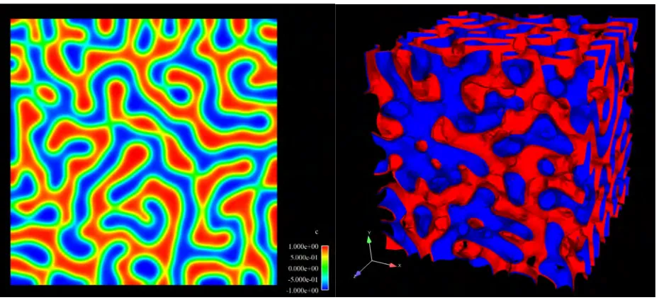
The next advance for the BISON fuel performance capability is to directly solve the phase field problem in a three dimensional calculation without calling an auxiliary code to calculate the thermal conductivity. To begin to explore this requirement, the Cahn-Hilliard 4th-order equation
was solved using JFNK and using C(1) continuous finite elements to allow its direct solution. The results of the Cahn-Hilliard solution are shown in Figure 8, where a two dimensional result is the left figure and a three dimensional solution is shown to the right. These results employed a mobility
,
an epsilon
,
and a mathematical free-energy function derivative
.
One might visualize this solution as a water surface on which oil was sprayed. Over time the oil drops tend to gather, separated by ever larger volumes of water. The colors correspond to the spatial concentration of the two components at a particular time. These images are a snapshot at a given time of a transient movie.
Mid
State
Figure 8. Spinodal decomposition: two and three dimensional solutions of the Cahn-Hilliard
equation system.
7
CONCLUSION
This work explored the use of a software platform, BISON, for the calculation of a fully-coupled equation system describing a mock fuel performance problem. The equations of thermomechanics and oxygen diffusion were solved using the JFNK method and the results were compared to literature. The JFNK solution method showed itself to be very capable for this application.
Next, explicit cladding geometry was added to the above model and several representative calculations were performed. Lastly, a set of calculations were conducted to begin to study issues with multiscale multiphysics coupling using JFNK, by coupling a phase field mesoscale solution to the above engineering scale fuel performance calculation. The results, while currently limited in scope, were very encouraging.
Acknowledgements. Work supported through the INL Laboratory Directed Research & Development (LDRD) Program under DOE Idaho Operations Office Contract DE-AC07-05ID14517 (INL/CON-09-15900).
REFERENCES
Hohorst, J., 1990 SCDAP/RELAP5/MOD2 Code Manual, Volume 4: MATPRO–A Library of Materials Properties for Light-Water-Reactor Accident Analysis, Tech. rep., NUREG/CR-5273, EGG-2555
Knoll, D.A., and Keyes, D.E., 2004 Jacobian-Free Newton-Krylov Methods: a Survey of Approaches and Applications, J. Comput. Phys., Vol.193:2, P.357–397
Newman, C., Hansen, G., and Gaston, D., 2009 Three Dimensional Coupled Simulation of
Thermomechanics, Heat, and Oxygen Diffusion in UO2 Nuclear Fuel Rods, J. Nuclear Materials, in press
Pope, M.A., and Mousseau, V.A., 2007 Accuracy and Efficiency of a Coupled Neutronics and Thermal Hydraulics Model, in The 12th International Topical Meeting on Nuclear Reactor Thermal Hydraulics (NURETH-12), Sheraton Station Square, Pittsburgh, Pennsylvania, U.S.A., Log Number: 239
Ramirez, J., Stan, M., and Cristea, P., 2006 Simulations of heat and oxygen diffusion in UO2 nuclear fuel rods, J. Nucl. Materials, Vol. 359:3, P.174–184