T
ABLE OF
C
ONTENTS
TABLE OF CONTENTS --- I
TABLE OF EXAMPLES--- IV
TABLE OF FIGURES --- V
WARRANTY --- VII
CHAPTER ONE --- 1
GETTINGSTARTED---1
HOWTOUSETHISUSERGUIDE---1
INTRODUCTION---1
Overview --- 2
Keypad--- 2
Printer --- 3
Start-up (or Reset) Report--- 3
Audit Trail--- 4
Setting the Mode--- 4
EVERYDAYUSE---5
System Status Check --- 5
Management Access --- 6
Error Keys (Cancel and Delete)--- 7
Setting the Time --- 8
Setting the Date and Day--- 9
CHAPTER TWO --- 10
REFERENCE--- 10
REPORTS--- 10
Activity Reports--- 10
Activity Report Clear --- 12
PROGRAMS--- 13
Program 1 - Fixed Rates --- 14
Program 2 - Grace Periods and Threshold Billing --- 16
Program 3 - Cost Adjustments--- 18
Program 6 - Print No Charge Calls (Yes/No) --- 22
Program 7 - Print Audit Trail --- 22
Program 8 - Store No Charge Calls --- 23
Program 9 - Send Administrative Calls --- 23
Program 10 - Programmable Parameters Report --- 23
Program 11 - Set Default Programmable Parameters for Program 1 through Program 9--- 24
Program 12 - Set Default Programmable Parameters for Everything that is not Set by Program 11--- 25
Program 14 - Set Top of Page --- 27
Program 20 - Print Status of Program 21 through Program 29 27 Program 21 - Add/Change Administrative Extensions --- 28
Program 22 - New Interim Area Code--- 30
Program 23 - Add Exchange On Site --- 31
Program 24 - Program Trunk/Access Code On Site--- 32
Program 26 - Lines/Page, Lines to Tear Off, SMDR/Remote Port Baud Rate and AM/PM vs. Military Time--- 34
Program 27 - The Universal Number Loop--- 38
Program 28 - Automatic Printing and Clearing --- 38
Program 30 - Download New Tariff Data Chip--- 38
Program 32 - Print List of Changeable SMDR Parameters and Ruler Line --- 40
Program 33 - Set SMDR Related Parameters --- 41
Program 248 – Restore System Settings From Flash Data Chip.44 Program 842 – Program Current System Settings to Flash Data Chip--- 45
Program 1739 - Erase Call Record Memory --- 46
ALARMS--- 47
General Information About Alarms --- 47
911 and 311 Alarms--- 47
Printer Alarm (Power, Paper, Ribbon, Off-line) --- 47
INN-FORM XL Power Alarm--- 49
SMDR DATA--- 49
APPENDICES --- 50
SYSTEMINSTALLATION--- 50
THEPRODUCTCHECKLIST--- 51
INSTALLING ANDREPLACING THEFLASHDATACHIP--- 51
CONNECTING THEPRINTER--- 53
CONNECTING TO THETELEPHONESYSTEM--- 56
CONNECTING THEPOWER--- 57
THEKEYPADTEST--- 58
CONNECTING THEREMOTEPORT--- 60
PROPERTY MANAGEMENT SYSTEMS (PMS)--- 62
PMS-HX (HOLIDEX) INTERFACE--- 62
Condition 1--- 62
Condition 2--- 63
Data Format Specification --- 64
Responses --- 66
Specification Link Control Characters --- 68
PMS-HB (HOBIC) INTERFACE--- 69
Condition 1--- 69
Condition 2--- 70
Condition 3--- 70
Data Format Specification --- 71
Field Descriptions--- 72
Responses When Not Using ACK/NAK --- 73
Responses While Using ACK/NAK --- 73
Specification Link Control Characters --- 74
PMS-MR (MICROS) INTERFACE--- 75
Condition 1--- 75
Condition 2--- 76
Data Format Specification --- 77
Responses --- 78
Specification Link Control Characters --- 79
TROUBLESHOOTING --- 80
Program 0 (Simulate Test Call) --- 88
Program 88 (Serial loop test)--- 89
Program 89 (Remote Port Loop Test) --- 90
GLOSSARY--- 92
QUESTIONS & ANSWERS --- 105
SERVICE AND MAINTENANCE --- 107
T
ABLE OF
E
XAMPLES
EXAMPLE: AUDITTRAIL---4
EXAMPLE: SYSTEMSTATUSCHECK---6
EXAMPLE: 4:55 P.M.WOULD BE HOUR16MINUTE55. ---8
EXAMPLE: ACTIVITYREPORTCLEAR--- 12
EXAMPLE: MESSAGE FORPROGRAM11. --- 25
EXAMPLE: MESSAGE FORPROGRAM12. --- 26
EXAMPLE: FORSETTINGSERIALBAUDRATES: --- 37
EXAMPLE: CALLRECORDPRINTED ONAUDITTRAIL(MODE9). --- 60
EXAMPLE: ONELINEAUDITTRAIL--- 62
EXAMPLE: FOUR LINEAUDITTRAIL FORHX --- 63
EXAMPLE: PMS-HX INTERFACEDATAFORMAT--- 64
EXAMPLE: ONELINEAUDITTRAIL--- 69
EXAMPLE: FULLFOUR-LINEAUDITTRAIL FORHB --- 70
EXAMPLE: PMS-HB INTERFACEDATAFORMAT--- 71
EXAMPLE: FOUR LINEAUDITTRAIL FORMR--- 76
EXAMPLE: PMS-MR INTERFACEDATAFORMAT--- 77
T
ABLE OF
F
IGURES
FIGURE1: START-UP(ORRESET) REPORT---4
FIGURE2: DAILYACTIVITYREPORT. --- 11
FIGURE3: PROGRAM10 STATUSREPORT--- 24
FIGURE4: PROGRAM20 STATUSREPORT--- 28
FIGURE5. BAUDRATECODENUMBERS--- 36
FIGURE6: PROGRAM32 STATUSREPORT--- 41
FIGURE7. CHANGEABLESMDR PARAMETERS 1THROUGH47FORPROGRAM33.--- 43
FIGURE8. SOME COMMON VALUES FORSMDR #47. --- 43
FIGURE9. LOCATION OFSYSTEMCHIPS--- 52
FIGURE10. SERIALPRINTERRJ11 JACK--- 54
FIGURE11. PINOUT FORSERIALPRINTERRJ11-TO-DB25M ADAPTER54 FIGURE12. BACKVIEW OFINN-FORM XL --- 55
FIGURE13. SMDR RJ-11 JACK--- 56
FIGURE14. PINOUT FORSMDR RJ11-TO-DB(25OR9) ADAPTER---- 57
TEL electronics, inc. reserves the right to add, delete or alter any of the information contained in this document without notice. Furthermore,TEL electronics, inc. makes no warranty on this document, and is not liable for damage or loss which may occur from its use.
TEL electronics, inc.and INN-FORM XL are trademarks of
TEL electronics, inc.
© Copyright by TEL electronics, inc. 1991 - 2005
All right reserved. No part or parts of this manual may be copied, reproduced, stored in a retrieval system or
transcribed in any form or by any means without the express and written permission ofTEL electronics, inc.
W
ARRANTY
TEL electronics, inc.(TEL) warrants that the INN-FORM XL system will perform in substantial compliance with the documentation supplied with this system. If the system is defective, TEL will replace it at no charge, assuming the defective system is returned to TEL. TEL warrants the INN-FORM XL from defects due to materials and/or workmanship for a period of two years. In no event will TEL be liable for any damages, including any loss of profits, loss of savings or other incidental or consequential damages arising out of the use or inability to use the INN-FORM XL (even if TEL or an authorized TEL dealer or distributor has been advised of the possibility of such damages), or for any claim by any other party.
INN-FORM XL User Guide Reader Comments
To Users of this User Guide:
We would appreciate your assistance in keeping this User Guide as up to date and helpful as possible. Please note in the space provided below any comments, questions,
corrections or suggestions you may have for future versions of this User Guide. Attach additional pages as needed.
Comments:
If you would like a written response to your comments, please print your name and address in the space below.
Name:
Company:
Address:
City: State: Zip:
Telephone:
Please mail this form to:
INN-FORM XL User Guide Operation Information
This page presents information that is important for the proper operation of this Call Accounting and Management System. If you wish to keep this information confidential, please remove this page and place it in a secure location.
Thank you.
Serial Number: ______________________________
Baud Rates:
SMDR/Serial Printer Port: _______________
Remote Port: __________________________
C
HAPTER
O
NE
G
ETTINGS
TARTEDH
OWT
OU
SET
HISU
SERG
UIDEThis user guide is designed to help you become
comfortable and proficient in using the INN-FORM XL Call Accounting and Management System.
This user guide begins with basic information on
everyday use, followed by complete instructions to each program and report.
As a system user, you’ll find most of the information you need in the beginning sections. As an installer or dealer, you’ll often refer to the programming and
installation sections, which are technically oriented. All keys that you are instructed to press are bolded; when you see ENTER, press the enter key.
I
NTRODUCTIONTEL electronics, inc.(TEL) is one of the largest manufacturers of telephone call accounting and management systems in the U.S. Each stand-alone system includes its own microprocessor and provides a maximum number of capabilities, yet takes a minimal amount of space.
Due to an overwhelming response and market demand, new models have been added to TEL’s family of telephone call accounting systems. These products are designed to provide years of reliable service to
O
VERVIEWThe INN-FORM XL is a sophisticated telephone call accounting system designed especially for the hotel / motel industry. Every call record received is checked, costed, and accounted.
Each call will also be transmitted to the Property Management System interface if one is connected, or if the unit has reports capabilities, each call will be stored in memory to be used in later printed reports.
Rate increases, surcharges, mark-ups and other parameters are all programmable on site.
K
EYPADThe keypad is used to initiate reports and enter data in the INN-FORM XL. The keys are color-coded to indicate the type of functions involved. Each time a key is properly pressed a “beep” sound will be heard and a response will appear in the display window.
Located next to the display window you will notice two LEDs (Light Emitting Diodes): the LOW MEM. light will go on whenever there is limited space in memory (in INN-FORM XL with Reports version), and the SMDR Data light will flicker green when call record data is being received. (See Appendix A.)
P
RINTERTEL electronics, inc.can provide a printer for each system, but most standard parallel or RS-232 serial impact printers will work with the INN-FORM XL. Before getting started, be sure to:
• Read and understand the printer manual. • Plug the printer in properly.
• Connect the printer cable properly. • Load paper.
• Turn the printer on.
• Select the printer or position on-line.
• Make sure that SMDR #18 value is correct for either serial or parallel printer (See Program 32).
• If using a serial printer, make sure the baud rate of the printer and the INN-FORM XL are the same.
S
TART-
UP(
ORR
ESET) R
EPORTWhen the system is first turned on, the printer will print a Start-up Report which includes: the site information, the sites area code and exchange, the serial number; the software release number; the model name, the Property Management System type, the memory size, the date, time, and day of the week, the current mode, the programmed options, and the copyright information. This report appears every time you reset or power-up your system (See Figure 1).
Figure 1: Start-up (or Reset) Report
A
UDITT
RAILThe Audit Trail will provide a printed record for each call immediatelyafterthe call is completed.
Every time a valid call is completed, call data is processed and, if the Audit Trail parameter has been turned on, the printer will print a one-line Audit Trail.
EXAMPLE: Audit Trail
Each line of the Audit Trail will identify the current date, time, day of the week, extension or room number, state called, number dialed, duration, charge and type of call. The Audit Trail option can be turned on or off as needed (see Program 7 and Program 26).
Extensions programmed as administrative will be marked by an asterisk and the cost of the calls will be printed instead of the charge (see Program 21).
S
ETTING THEM
ODETheMODE SETkey is used to set the diagnostic mode of the INN-FORM XL.
********************************************************************* TEL Inn of Everybody's Town U.S.A. 801-756 #C356012345
Release 18.0 INN-FORM XL BASIC with 0 call records, 4/12 at 5:07PM We Mode 0. Options: Print Audit Trail, Ram Setup
(c) 1986-2005 TEL electronics, inc. DM: 2
*********************************************************************
NOTE: Under most circumstances the mode should be left in the normal operating mode (0). Management Access will have to be activated in order to change the mode.
>To set the mode:
Step 1. PressMODE SET.
Step 2. Enter the mode desired (0, 7, 8 or 9).
Step 3. PressENTER.
The modes are as follows:
0 = NORMAL OPERATING MODE
7 = UTILITY MODE - Prints non-call data (including wake-up calls ) in addition to the Audit Trail.
8 = PASS-THROUGH MODE - Prints everything received from the telephone switch as well as the Audit Trail (if the Audit Trail parameter has been turned on).
9 = CHECKING MODE - Prints the same data as mode 8, but also compares each SMDR record to see if it matches the factory programmed
specifications included in the INN-FORM XL. When SMDR data cannot be processed, a message
is printed.
E
VERYDAYU
SESystem Status Check
properly. If there is a six hour period that should have recorded calls but did not, contact your dealer.
EXAMPLE: System Status Check
M
ANAGEMENTA
CCESSThe Management Access key allows entry of a predefined Management Access Number (up to four numeric digits) which permits only authorized personnel to access reports and program the system. After a legitimate Management Access Number is entered and work is completed, pressingMGMT. ACCESSagain will cancel the Management Access entry and prevent unauthorized access until the Management Access Number is entered again.
Your Management Access Number is a safeguard for your system’s information. Usually, this number is selected at the time the system is ordered and specified on the order form. It is pre-programmed into the system as it is built and customized to your specification. (For additional programming instructions see Program 29, Multiple Levels of Management Access.)
NOTE: If your system does not use a Management Access Number pressMGMT. ACCESSand you will be given access without entering an access number.
>To access Management Access:
Step 1. PressMGMT. ACCESS. The system will display, “MGMT ACCESS?”
Step 2. Enter your Management Access Number.
Step 3. PressENTER. (Management Access has been activated.)
Step 4. To exit Management Access mode press MGMT. ACCESS.
NOTE: If an incorrect number is entered, the display will read. “INVALID” momentarily, then the system displays the current date and time. To start over, pressMGMT. ACCESS again and enter the correct number.
E
RRORK
EYS(C
ANCEL ANDD
ELETE)
These keys are used to cancel an entire entry, a report in progress (except Audit Reports), or to delete the last character entered in case of an entry error.
PressCANCELto cancel an entry or report in progress. When entering keystrokes for an Audit Report,CANCELmust be pressed prior to pressing SUMMARYorDETAIL. Once the Audit Report is under way it cannot be canceled.
S
ETTING THET
IMEThe Time Set Key allows the correct time to be set in the system for proper pricing and reporting of call data.
The correct time is important because the system must know exactly what time calls are made to apply correct charges. It is vital for identifying day rates, night rates, evening rates, etc. The correct time should be set when the system is installed and when changes are necessary due to daylight savings.
>To set the time:
Step 1. PressTIME SET. The system will display, “HOUR?”
Step 2. Enter the hour (0 through 23).
Step 3. PressENTER. The system will display, “MINUTE?”
Step 4. Enter the minute (0 through 59).
Step 5. PressENTER. (The time has now been set.)
NOTE: The system time must be set using military time. Enter one or two digits which represent the hour of the day. Military time is 24 hours, so if it is after 12:00 noon add the hour to 12. Thus, 3:00 is 15; midnight is 0; and one minute before midnight is 23:59.
S
ETTING THED
ATE ANDD
AYThe Date Set Key allows you to set the correct date and day of the week in the system.
The date and day are vital for rating calls and applying correct charges (weekday rates versus weekend rates). The date and day will need to be set when the system is installed.
> To set the date:
Step 1. PressDATE SET. The system will display, “MONTH?”
Step 2. Enter the month (1 through 12).
Step 3. PressENTER. The system will display, “DAY?”
Step 4. Enter the day of the month (1 through 31).
Step 5. PressENTER. The system will display, “WEEKDAY (1 = SUN)?”
Step 6. Enter the day of the week (Sunday = 1, Saturday = 7).
C
HAPTER
T
WO
R
EFERENCER
EPORTSA
CTIVITYR
EPORTSNote: For Activity Reports and other reports included in the INN-FORM XL with Reports version see Addendum.
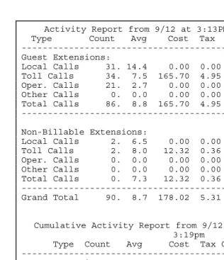
This report summarizes guest and administrative telephone activity into the following information: four types of calls, number of calls, average time per call, cost of calls, tax applied to cost, rebilling charges, sales tax on charges and gross profit.
For an example of an activity report see Figure 2. The top portion of the report will automatically clear each time the report is run. The bottom portion can be cleared manually as often as needed (see Clear Activity Report). If not cleared, the bottom portion will
continue to accumulate data.
> To print an Activity Report:
Figure 2: Daily Activity Report.
Activity Report from 9/12 at 3:13PM thru 9/12 at 3:19pm Type Count Avg Cost Tax Charged Tax Profit ---Guest Extensions:
Local Calls 31. 14.4 0.00 0.00 5.00 0.00 5.00 Toll Calls 34. 7.5 165.70 4.95 307.62 0.00 136.97 Oper. Calls 21. 2.7 0.00 0.00 14.00 0.00 14.00 Other Calls 0. 0.0 0.00 0.00 0.00 0.00 0.00 Total Calls 86. 8.8 165.70 4.95 326.62 0.00 155.97 ---
Non-Billable Extensions:
Local Calls 2. 6.5 0.00 0.00 0.00 0.00 0.00 Toll Calls 2. 8.0 12.32 0.36 0.00 0.00 -12.68 Oper. Calls 0. 0.0 0.00 0.00 0.00 0.00 0.00 Other Calls 0. 0.0 0.00 0.00 0.00 0.00 0.00 Total Calls 0. 7.3 12.32 0.36 0.00 0.00 -12.68 --- Grand Total 90. 8.7 178.02 5.31 326.62 0.00 143.29
Cumulative Activity Report from 9/12 at 3:13PM thru 9/12 at 3:19pm
Type Count Avg Cost Tax Charged Tax Profit ---Guest Extensions: Local Calls 31. 14.4 0.00 0.00 5.00 0.00 5.00 Toll Calls 34. 7.5 165.70 4.95 307.62 0.00 136.97 Oper. Calls 21. 2.7 0.00 0.00 14.00 0.00 14.00 Other Calls 0. 0.0 0.00 0.00 0.00 0.00 0.00 Total Calls 86. 8.8 165.70 4.95 326.62 0.00 155.97 --- Non-Billable Extensions:
A
CTIVITYR
EPORTC
LEARNote: For Activity Reports in the INN-FORM XL with Reports version see Addendum.
TheACTIVITY REPORT CLEARkey clears the data for the Activity Report and begins a new report time frame.
> To clear an Activity Report:
Step 1. PressACTIVITY REPORT CLEAR.
Step 2. The unit will display "ARE YOU SURE?"
Step 3. PressYES.
The Activity Report will be cleared and a new set of data will begin to accumulate.
P
ROGRAMSNOTE: Management Access must be activated before using the Program Key.
The programs can be classified in the following ways:
• Programs 10, 20, and 32 are status reports on the
current setup of the INN-FORM XL system. Print out a copy of these reports before changing the program.
• Programs 1 through 9 control how the call record data from the switch will be priced and handled.
• Programs 11 and 12 return the system to factory programmed defaults.
• Programs 14 through 33 control how the system receives and processes the data.
To understand programming of rates, it is important to understand telephone company charges, and the charges calculated by the INN-FORM XL.
First, charges from the phone company are called costs in this user guide to distinguish them from the final amounts to be charged.
parameters on site by the user. Costs are thus determined, based upon a large set of complicated tariff and other data which must be included in every INN-FORM XL.
The INN-FORM XL calculates both the cost and charge for every call. The system analyzes the number dialed and the duration of the call in order to calculate basic cost based on the telephone company rates that are programmed into the system.
The INN-FORM XL then determines if a cost percentage adjustment is necessary, and if so, applies the adjustment, and then adds any appropriate tax. This is the total cost of the call. The system then adds a mark-up percentage and surcharge and sales tax, if any to arrive at the final charge. The difference between the cost and charge is the profit made for each call.
EXCEPTIONS: As usual, there are exceptions. In some areas, particularly in major metropolitan areas, local calls are called "Measured Service calls" and are charged based on distance and duration like long distance calls. Each INN-FORM XL includes data for such measured service areas. If WATS or other special Trunks are used, the INN-FORM XL will calculate costs correctly.
NOTE: In this user guide local calls in a measured service area are referred to as nearby calls.
P
ROGRAM1 - F
IXEDR
ATESNote: See Program 1 in Addendum for INN-FORM XL with Reports version.
> To run Program 1:
Step 1. After you've entered your management access code: PressPROGRAM. The system will display, "PROGRAM".
Step 2. Enter1.
Step 3. PressENTER. The system will display, "FIXED RATE #".
Step 4. Enter a number (1 through 8) where:
1 = Local Calls
2 = Operator Assisted Calls 3 = Local Information 4 = In-state Information 5 = U.S. Information 6 = 1- (8XX) Calls 7 = 1- (900) Calls 8 = Incoming Calls
Step 5. PressENTER. The system will ask for the selected rate number, such as, "RATE 6?"
Step 6. Enter the rate for that selected category in cents, or in dollars and cents using the decimal point where appropriate (0 through 99.96).
EXAMPLE: 25 = 25 cents and 2.00 = 2 dollars
It is possible to send regular toll calls to the PMS and print in the Audit Trail, and simultaneously deal with no charge fixed rate calls in special ways independent of the settings of Programs 6 and 8. Entering the amounts listed below as fixed rate charges for any of the fixed rate calls which have no charge (fixed rate calls 1 through 8) indicates a zero charge call which will be treated differently.
Charges Action
$99.99 Printed
$99.97 Not printed
Note:With the Audit Trail on, all calls that are printed will be posted to the PMS as well. In contrast, if a call is not printed it will not be posted to the PMS either. To turn the Audit Trail off see Program 26 (or Program 7 for the INN-FORM XL with Reports version).
Note:For more general control over printing no charge calls, see Program 6.
P
ROGRAM2 - G
RACEP
ERIODS ANDT
HRESHOLDB
ILLINGNOTE: The use of grace periods is required because of the telephone system, not because of the INN-FORM XL. Telephone call accounting and management system must use a grace period method because generally there is no signal available from the telephone company to signify whether a call has reached the dialed party or not.
> To run Program 2:
Step 1. After you've entered your management access code: PressPROGRAM. The system will display, "PROGRAM".
Step 2. Enter2and pressENTER. The system will display, "GRACE PER".
Step 3. Enter the grace period number (1 through 6) where:
1 = Local Calls 2 = Operator Assisted 3 = Information 4 = 1-(900) Calls 5 = International Calls 6 = Other Calls 7 = 8XX 8 = Thresh
NOTE:After programming grace period 7 (8XX) or 8 (Thresh), you will be prompted for a rate. This is a per minute rate to be charged after the grace period has been exceeded. (To also include a flat fee prior to the per minute rate, see Program #1 for Local and 8XX calls).
Step 4. PressENTER. The system will ask for the selected grace period number, such as, "PERIOD 1?" for local calls.
Step 6. PressENTER.
NOTE: Grace period values are loaded at the factory based upon the best information available, but some adjustments could be appropriate on site.
P
ROGRAM3 - C
OSTA
DJUSTMENTSThis program option allows you to keep up with rate increases (or decreases) from the phone company as they occur. This percentage increase is applied to the calculated cost of each tariffed or toll call to arrive at a new adjusted cost.
> To run Program 3:
Step 1. After you've entered your management access code: PressPROGRAM. the system will display, "PROGRAM"
Step 2. Enter3and pressENTER.
The system will display, "COST ADJ% #".
Step 3. Enter a number (1 through 6) where:
1 = Nearby 2 = In-State 3 = In USA 4 = International 5 = WATS 6 = Special
Step 5. Enter the percentage for that selected category, using a decimal point if desired (-100.00 through 100.00). The percentage can be negative (-100 would mean a decrease in cost of -100%, or free).
Step 6. PressENTER.
P
ROGRAM4 - M
ARK-U
PSA mark-up is a percentage to be added after the cost has been calculated in order to determine the charge to a client, tenant, etc.
For example, if your cost is $1.00 and a mark-up of 50% is set, the client would be charged $1.50 for that call (assuming that other parameters are not
considered).
Thus, the mark-up option is used to add an amount to the cost in order to recover overhead, labor and other expenses and/or to provide a profit on phone activities. The mark-up option is not designed to be used to reflect increases made by the local phone company. See Cost Adjustments, Program 3 for tariff rate changes.
> To run Program 4:
Step 1. PressPROGRAM. The system will display, "PROGRAM".
Step 2. Enter4.
Step 4. Enter the number (1 through 6) where:
1 = Nearby 2 = In-State 3 = In USA 4 = International 5 = WATS 6 = Special
Step 5. PressENTER. The system will ask for the selected mark-up, such as, "PERCENT 4?" for international mark-up adjustment.
Step 6. Enter the percentage selected (-100 through 999).
Step 7. PressENTER.
P
ROGRAM5 - S
URCHARGESA surcharge is a flat, one time fee to be added after the cost, including Mark-ups, has been calculated in order to determine the charge to a client, tenant, etc.
For example, if the telephone company cost of a call were $1.00 and you select a $1.00 surcharge, a guest will be charged $2.00 for that call (assuming that other parameters are not considered).
such increases should be programmed using Cost Adjustments Program 3.
> To run Program 5:
Step 1. PressPROGRAM. The system will display, "PROGRAM".
Step 2. Enter5.
Step 3. PressENTER. The system will display, "SURCHARGE".
Step 4. Enter a number (1 through 6) where: 1 = Nearby
2 = In-State 3 = In USA 4 = International 5 = WATS 6 = Special
Step 5. PressENTER. The system will display the selected surcharge number such as, "AMOUNT 5?" for WATS calls.
Step 6. Enter the surcharge amount ($0.00 through $327.67) in cents, or in dollars and cents using a decimal point where appropriate.
P
ROGRAM6 - P
RINTN
OC
HARGEC
ALLS(Y
ES/N
O)
This program option determines whether to print or not print in the Audit Trail those calls that have not had a charge added (i.e., incoming and internal calls).
> To run Program 6:
Step 1. After you've entered your management access code: PressPROGRAM. The system will display "PROGRAM".
Step 2. Enter6 and pressENTER. The system will display, "PRINT 0$?".
Step 3. PressYESto print all no charge calls, or pressNOif no charge calls are not to be printed in the Audit Trail.
Note:With the Audit Trail on, all calls that are printed will be posted to the PMS as well. In contrast, if a call is not printed it will not be posted to the PMS either. To turn the Audit Trail off see Program 26 (or Program 7 for the INN-FORM XL with Reports version).
Note: For additional control options over printing no charge calls see Program 1.
P
ROGRAM7 - P
RINTA
UDITT
RAILNote: For Program 7 in INN-FORM XL with Reports version see Addendum.
P
ROGRAM8 - S
TOREN
OC
HARGEC
ALLSNote: For Program 8 in INN-FORM XL with Reports version see Addendum.
P
ROGRAM9 - S
ENDA
DMINISTRATIVEC
ALLSNote: For Program 9 (Store Admin. Calls) in INN-FORM XL with Reports version see Addendum.
An administrative call comes from an administrative extension (see Program 21) and is priced at cost. This program allows you to send or not send administrative calls to the Property Management System.
> To run Program 9:
Step 1. After you've entered your management access code: PressPROGRAM. The system will display, "PROGRAM #".
Step 2. Enter9.
Step 3. PressENTER. The system will display, "SEND ADMIN?"
Step 4. PressYESto send administrative calls or NOto not send administrative calls.
P
ROGRAM10 - P
ROGRAMMABLEP
ARAMETERSR
EPORTNote: For Program 10 using the INN-FORM XL with Reports version see Addendum.
> To run Program 10:
Step 1. PressPROGRAM. The system will display, "PROGRAM".
Step 2. Enter10 and pressENTER. The report will print similarly to what is seen in Figure 3.
Figure 3: Program 10 Status Report
P
ROGRAM11 - S
ETD
EFAULTP
ROGRAMMABLEP
ARAMETERS FORP
ROGRAM1
THROUGHP
ROGRAM9
This program permits you to restore Programs 1 through 10 to factory programmed defaults (or the values that have been programmed into the flash Data Chip with a Program 842).
NOTE: Using this option will erase all programming you have done with Program 1 through 9.
TEL Inn of Everybody's Town U.S.A. 801-756 #C356012345
Release 18.0 INN-FORM XL BASIC with 0 call records, 7/23 at 5:07PM We Mode 0. Options: Print Audit Trail, Ram Setup
(c) 1986-2005 TEL electronics, inc. DM: 2
Prog. #10-Price Settings
1 2 3 4 5 6 7 8 Local Oper. Loc Inf St Inf U.S.Inf 1-(8xx) 1-(900) Incom 1.Fixed Rates: 0.25 1.00 0.25 0.25 0.60 0.50 0.50 0.00
Local Oper. Info. 1-(900) Intern. Other 1-(8xx) Thresh 2.Grace Period: 60 30 20 20 75 60 20 0 Rate: 0.10 0.00
Nearby In-State In-U.S.Intern. WATS Special 3.Cost%Adjust: 0.00 0.00 0.00 0.00 0.00 0.00 4.Mark-up%: 0 40 40 40 0 0 5.Surcharge: 0.00 1.50 1.55 2.55 0.00 0.00 6.Print No Charge Calls: No
> To run Program 11:
Step 1. After you've entered your management access code: PressPROGRAM. The system will display, "PROGRAM #".
Step 2. Enter11and pressENTER.
Step 3. PressYESto restore the system Data Chip default values or pressNOto abort this option.
The system will print a message similar to the one that follows:
EXAMPLE: Message for Program 11.
P
ROGRAM12 - S
ETD
EFAULTP
ROGRAMMABLEP
ARAMETERS FORE
VERYTHING THAT IS NOTS
ET BYP
ROGRAM11
This program permits you to restore all the remaining programmed information (information not returned to factory defaults by Program 11) to the factory
programmed defaults (or the values that have been programmed into the flash Data Chip with a Program 842).
NOTE: Using this option will erase programming you have done, as well as the definition of the Multiple Reports. It also sets the diagnostic mode to 0.
> To run Program 12:
Step 1. After you've entered your management access code: PressPROGRAM. The system will display, "PROGRAM".
Step 2. Enter12and pressENTER.
Step 3. PressYESto restore the system to Data Chip defaults or pressNOto abort this option.
The system will print the following message:
EXAMPLE: Message for Program 12.
Step 4. Press the reset key, (located in the upper right corner of the unit the telephone with the dollar sign) to load defaults from the Data Chip.
P
ROGRAM14 - S
ETT
OP OFP
AGEThis program will define where the top of page should be set so the system may leave the desired amount of space between reports.
> To run Program 14:
Step 1. Position the paper in the printer so the top of the form is at the tear off bar, or position the paper to your specifications.
Step 2. PressPROGRAM. The system will display, “PROGRAM".
Step 3. Enter14and pressENTER. The system will momentarily display, "OK".
P
ROGRAM20 - P
RINTS
TATUS OFP
ROGRAM21
THROUGHP
ROGRAM29
Note: For Program 20 using INN-FORM XL with Reports version see Addendum.
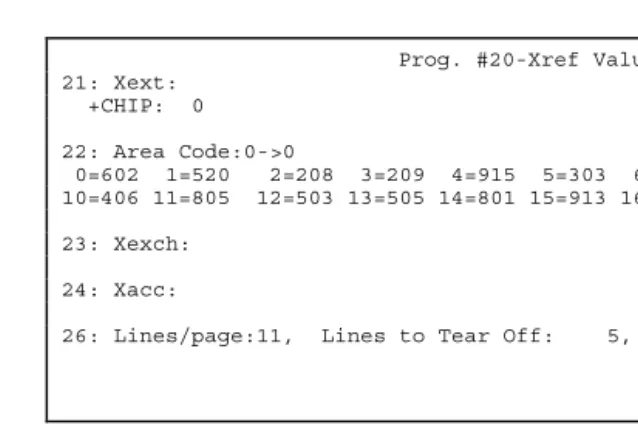
This program prints a report listing the current status of Program 21 through Program 29. (Currently there is no Program 25).
> To run Program 20:
Step 1. Press PROGRAM. The system will display "PROGRAM #".
Figure 4: Program 20 Status Report
Note: The Program 20 report has an option that allows the user to view the room extension and administrative cross references that were permanently programmed into the Flash Data Chip at the factory. This can be accomplished by performing aProgram -20.
P
ROGRAM21 - A
DD/C
HANGEA
DMINISTRATIVEE
XTENSIONSThis program option allows you to change the
administrative or guest status of up to 100 extensions. This is particularly useful for newly added
administrative extensions.
It is also useful if there are rooms with two extensions and you wish the charges of both extensions to appear on one. Thus it is possible to program the second extension to print and store calls made on it, to the first extension. When combining extensions, you would enter the extension number that you wish to store under a different extension in Step #4. Then enter the
extension that will store the calls for both extensions in
Prog. #20-Xref Values 21: Xext:
+CHIP: 0
22: Area Code:0->0
0=602 1=520 2=208 3=209 4=915 5=303 6=970 7=316 8=817 9=405 10=406 11=805 12=503 13=505 14=801 15=913 16=909 17=619 18=702 19=719
23: Xexch:
24: Xacc:
> To change an extension to an administrative extension or to combine extensions:
Step 1. After you've entered your management access code: PressPROGRAM. The system will display, "PROGRAM"
Step 2. Enter21.
Step 3. PressENTER.
Step 4. The system will display, "FROM:" Enter the extension number you want to be administrative (0 through 29999).
Step 5. PressENTER.
Step 6. The system will display, "TO:" To make the extension administrative, enter a dash (-) followed by the extension number.
Step 7. PressENTER. The system will display, "FROM:".
The system will remain in the data entry mode until you pressCANCELorENTERto quit.
> To delete a current administrative extension to a guest extension:
Step 1. When the system displays, "FROM:", enter the extension number you want to delete just as you originally entered it.
NOTE: To change a current administrative extension to a guest extension, at the "FROM:" prompt, enter a dash (-) followed by the extension number. At the "TO:" prompt, enter the extension number. Make sure there are no calls recorded in memory for the extension at the time you change its status.
P
ROGRAM22 - N
EWI
NTERIMA
REAC
ODEIf an old Area Code is divided to create a new Area Code, use this program to have the new Area Code use the old Area Codes costs until new tariff data becomes available. A default rate is automatically used for unknown Area codes. Please note that only one new Area Code can be added on-site.
> To run Program 22:
Step 1. PressPROGRAM. The system will display, "PROGRAM".
Step 2. Enter22.
Step 3. PressENTER. The system will display, "NEW A.C."
Step 4. Enter the new three-digit Area Code.
Step 5. PressENTER. The system will display, "SAME A.C."
Step 6. Enter the old Area Code that has been divided to form the new Area Code.
P
ROGRAM23 - A
DDE
XCHANGEO
NS
ITEThis program allows you to assign up to 25 new Exchanges on site. This is only necessary for newly formed Exchanges which are relatively close. If the charges for calls to those Exchanges are significantly different than phone bills indicate, then you may wish to use this option.
> To run Program 23:
Step 1. After you've entered your management access code: PressPROGRAM. The system will display, "PROGRAM".
Step 2. Enter23and pressENTER. The system will display, "FROM:"
Step 3. Enter the new Exchange you want to assign.
Step 4. PressENTER. The system will display, "TO:"
Step 5. Enter the old Exchange which the new Exchange should be equivalent to.
Step 6. PressENTER. The system will display, "FROM:"
> To delete any unwanted Exchange entries:
Step 1. When the system displays, "FROM:" enter the Exchange whose entry you want to delete just as you originally entered it.
Step 2. PressENTER. The system will display, "DELETED!"
Note: The system will remain in the data entry mode until you pressCANCELorENTERto quit.
P
ROGRAM24 - P
ROGRAMT
RUNK/A
CCESSC
ODEO
NS
ITEThis program option allows you to assign or reassign up to 25 Trunk and/or access codes on site. This may be useful if your telephone system capabilities are increased or changed, and you have different types of Trunks (WATS, FX, etc.). Your system may be programmed to use the Trunk number as an access code to determine what type of call is dialed, or it may use an access code directly if it is available. Some analysis may be needed to determine if your system uses access codes or Trunks for this purpose.
> To run Program 24:
Step 1. After you've entered your management access code: PressPROGRAM. The system will display, "PROGRAM".
Step 3. PressENTER. The system will display, "FROM:".
Step 4. Enter the Trunk/access code you want to assign or reassign.
Step 5. PressENTER. The system will display, "TO:"
Step 6. Enter the existing Trunk/access code that the new Trunk access code will act like.
Step 7. PressENTER.
> To delete an unwanted access code entries:
Step 1. When the system displays, "FROM:" enter Trunk/access code whose entry you want to delete.
Step 2. PressENTER. The system will display, "DELETED!"
P
ROGRAM26 - L
INES/P
AGE, L
INES TOT
EARO
FF,
SMDR/R
EMOTEP
ORTB
AUDR
ATE ANDAM/PM
VS. M
ILITARYT
IMENOTE: Before you use Program 26, you should access Program 20 and print a copy of the current status of lines/page, baud rate, and AM/PM vs. military time. Review the status to determine if changes need to be made, and keep a copy to refer to during programming of Program 26.
This program will allow you to adjust the lines per page, lines to tear off, baud rate for both SMDR/Serial Printer and remote port and allow you to select whether your reports will be printed in AM/PM or military time format. When changing the Baud rate you will need to reset the unit before the new setting will take effect.
Entering 0 for lines per page and pressing the Reset Key (located in the upper right corner of the unit, the telephone with the dollar sign) will restore all four options as well as all of Program 33 to the original factory defaults.
> To run Program 26:
Step 1. PressPROGRAM.
Step 2. Enter26 and pressENTER. The system prompt will indicate, "LINES PAGE?"
Step 3. Enter the required number of lines per page.
Note: The default for lines/page is 11 and is the most commonly used value. If your requirements are different, consult your printer manual for the proper setting and set the lines/page accordingly.
Note: Entering a '1' for Lines/Page value will flag the INN-FORM XL to not print the one line audit trail.
Step 4. PressENTER. The prompt will indicate, "BAUD FACTOR?"
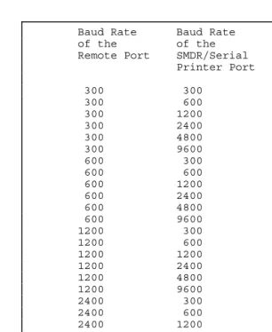
Figure 5. Baud Rate Code Numbers
NOTE: An SMDR and remote port baud rate were programmed into your INN-FORM XL at the factory according to your order. However, if a change in either baud rate is required, it can be made with this program.
Baud Rate Baud Rate Baud Factor Code of the of the You Use in Remote Port SMDR/Serial Program 26 Printer Port
EXAMPLE: For Setting Serial Baud Rates: Assume the INN-FORM XL you received is set with an Remote Port baud rate of 600 and a SMDR/Serial Printer baud rate of 300. Using the table in Figure 5, you discover that in order to work properly your system requires an SMDR baud rate of 1200. Refer to Figure 5 and notice that when you line up the remote port baud rate of 600 and the SMDR baud rate of 1200, the code number is 101. At the prompt 'BAUD
FACTOR?" you would enter the code number101.
Step 6. PressENTER. The system displays, 'AM/PM?"
Step 7. PressYESfor AM/PM or pressNOfor military time.
Step 8. If in Step 5 a new baud factor was entered. Press theResetKey (located in the upper right corner of the unit, the telephone with the dollar sign) to put the new baud rate into effect.
In order to properly page reports, the system must know how many lines to advance so the complete page may be torn off after printing. The default is five lines to the tear off point.
> To set the tear-off point:
Step 1. PressPROGRAM.
Step 3. Enter a dash (-) and the required number. The system will then set that number of lines to the tear off point.
Step 4. PressENTER. The system prompt will indicate, "BAUD FACTOR".
Step 5. PressENTERagain to exit Program 26 if you do not want to modify the baud factor.
NOTE: The newly changed baud rate will not be in effect until a RESET is performed on the unit.
P
ROGRAM27 - T
HEU
NIVERSALN
UMBERL
OOPNote: For Program 27 using the INN-FORM XL with Reports version see Addendum.
P
ROGRAM28 - A
UTOMATICP
RINTING ANDC
LEARINGNote: For Program 28 using the INN-FORM XL with Reports version see Addendum.
P
ROGRAM30 - D
OWNLOADN
EWT
ARIFFD
ATAC
HIPAs tariff rates or PBX and PMS systems are changed or modified, it may become necessary to change the entire Flash Data Chip in the INN-FORM XL. This process can be accomplished by either ordering a new Data Chip from the dealer and physically changing the chip (see INSTALLING ANDREPLACINGDATACHIP), or if an
> To run Program 30
Step 1. Talk with a dealer and order a new tariff Data Chip. You will be provided with the phone number to download the new Data Chip.
Step 2. Attach an RJ-11 type modular phone cable from a known good analog phone line (i.e. fax or modem line) to the modem jack on the left side of the INN-FORM XL unit.
Note: It is important that the line being used be an analog type phone line. Using a digital phone line could cause damage to either the phone line or the INN-FORM XL internal modem.
Step 3. Print out the reports in Programs 10, 20, and 32 before continuing to the next
step.
Step 4. PressPROGRAM. The system will display "PROGRAM".
Step 5. Enter30 andENTER. The system will display "CNNCT TYPE:"
Step 6. Press1 andENTER. The system will display "Phone#?".
Step 7. Enter the phone number that has been provided.
Step 8. PressENTER.
Note: At this point the INN-FORM XL is downloading the new Data Chip file from a modem server. The download usually takes about five minutes to complete. During that time the red LOW MEM. light should flash every few seconds to indicate that the download is in process.
Step 9. When the download is complete a message will print indicating the download was successful. The INN-FORM XL will perform an automatic Program 248 and reset itself to load in all of the Data Chip parameters.
P
ROGRAM32 - P
RINTL
IST OFC
HANGEABLESMDR
P
ARAMETERS ANDR
ULERL
INEThis program prints the current settings of the SMDR parameters (see Program 33) and a ruler line to help judge mode 8 or 9 printouts.
An SMDR parameter is the location and placement of the information (SMDR) that the INN-FORM XL receives from the telephone switch.
An SMDR parameter change should only be necessary at installation if the switch is sending different
information than that programmed into the Data Chip.
NOTE: It is suggested that you make a printout of the settings as they come from the factory and then another printout of any changes you make, so you will have the two records to refer and compare to.
> To run Program 32:
Step 1. PressPROGRAM. The system will display, "PROGRAM".
Step 2. Enter32 and pressENTER. The system will print the list of current SMDR parameters and the ruler line as seen in Figure 6.
Figure 6: Program 32 Status Report
P
ROGRAM33 - S
ETSMDR
R
ELATEDP
ARAMETERSThis program option allows you to set SMDR
parameters. Changing SMDR parameters can greatly alter the performance of your call accounting system. Make sure you understand the changes needed before using Program 33. Under normal operating conditions, no changes in SMDR parameters should be required. It is recommended that you contact your dealer before changing any SMDR parameters!
NOTE: It is strongly suggested that you keep a printout of the default settings and another printout of the changes you make, if
Prog. #32-SMDR Settings
0 2 15 2 18 2 21 0 0 26 34 3 24 4 62 0 73 0 0 0 0 0 0 0 2 4 20 0 58 47 58 48 0 0 0 0 0 1 0 85 9 0 62 24 0 1 -1 9
your telephone system are pre-programmed at the factory according to the information submitted with your order for your INN-FORM XL system.
> TO RUN PROGRAM 33:
Step 1. PressPROGRAM. The system will display, "PROGRAM".
Step 2. Enter33and pressENTER. The system will display, "SMDR#"
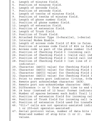
Step 3. Enter the parameter number (1 through 47, see Figure 7).
Step 4. PressENTER. The system will display, "VALUE (NN)?"
NOTE: NN is the current value of the parameter.
Step 5. Enter the correct value for the chosen parameter.
Step 6. PressENTER.
Figure 7. Changeable SMDR Parameters 1 through 47 for Program 33.
Figure 8. Some common values for SMDR #47.
2. Length of hours field. 3. Position of hours field. 4. Length of minutes field. 5. Position of minutes field. 6. Length of seconds field. 7. Position of seconds field. 8. Length of tenths of minutes field. 9. Position of tenths of minutes field. 10. Length of phone number field. 11. Position of phone number field. 12. Length of extension field. 13. Position of extension field. 14. Length of Trunk field. 15. Position of Trunk field.
18. Attached Printer Type (0=Parallel, 1=Serial Printer). 19. Internal Modem Enable.
22. Length of access code field if #24 is false. 23. Position of access code field if #24 is false.
24. Access code is part of the phone number (0=false, 1=true). 25. Position of Checking Field 0 (incoming call indicator, if used). 26. Position of Checking Field 1 (valid call indicator, 0=don't care). 27. Position of Checking Field 2 (valid call indicator, 0=don't care). 28. Position of Checking Field 3 (1st line of 2-line call record indicator).
29. Character (ASCII value) for Checking Field 0. 30. Character (ASCII value) for Checking Field 1. 31. Character (ASCII value) for Checking Field 2. 32. Character (ASCII value) for Checking Field 3.
33. Print to remote port indicator (1=true, 0=Use attached Printer). 34. Remote port acknowledge character (ACK).
35. Remote port non-acknowledge character (NAK).
36. Difference (+ or ?) from start time to end time (0=use duration field). 38. 24 hour (instead of 12 hour) format indicator if #36 not 0 (0=12hour). 39. Number of spaces between each Audit Trail line.
43. Position of extension field for incoming call (when #29 is found). 44. Position of Trunk field for incoming call (when #29 is found). 45. Position of extension field used for transfers (if 0 is read, use #13). 46. "011+" calls are not operator-assisted indicator (0=operator-assisted, 1 or 255=not operator-assisted).
47. Serial protocol value, number of data bits (7 or 8), parity (Odd, Even, or None)and number of stop bits (1 or 2). See Figure 8 below for some common values.
REMOTE PORT SMDR/SERIAL PRINTER SMDR #47 VALUE 7E1 8N1 -97 8E1 7N1 -37
8N1 7N1 -5
8N1 8N1 (most commonly used) -1
7O1 8N1 23
7N1 8N1 55
P
ROGRAM248 – R
ESTORES
YSTEMS
ETTINGSF
ROMF
LASHD
ATAC
HIP.
IMPORTANT: Make sure that Program 10, 20, and 32 reports are printed before performing a Program 248, as these may prove invaluable for comparison purposes.
Performing Program 248 will reset the INN-FORM XL to the default settings stored in the Flash Data Chip. The Flash Data Chip contains all the factory settings for the INN-FORM XL (or the on-site settings stored if a Program 842 has been performed). By performing a Program 248, any on-site settings made since the installation of the chip, or since the last Program 842, will be over written. This action will also clear the activity reports. Performing a Program 248 will also clear out all call records out of the memory if using an INN-FORM XL with Reports version.
> To run Program 248:
Step 1. Perform Programs 10, 20, and 32 before going any further. These will print the current on-site settings stored in the INN-FORM XL. These can be useful for comparison or troubleshooting purposes. Keep these for future reference.
Step 2. After entering the management access code pressPROGRAM. The system will display “PROGRAM”.
Step 4. Ensure the system is working by performing a test call and checking that the call posts to the printer and PMS (if applicable) with the correct pricing, mark-ups, surcharges, etc.
P
ROGRAM842 – P
ROGRAMC
URRENTS
YSTEMS
ETTINGS TOF
LASHD
ATAC
HIPPerforming a Program 842 stores the currenton-site
settings into the Flash Data Chip, replacing the factory default settings. A Program 842 can be performed as many times as needed to storeon-sitesetting changes.
> To run Program 842:
Step 1.Important: Make certain that the entire system is running in the manner desired including the following, before proceeding:
a) Pricing of calls including mark-ups, surcharges, etc. (See Program 10). b) Grace periods, threshold values, etc.
(See Program 10).
c) Desired call records are properly printing.
d) Desired call records are posting to property management system (if applicable).
Step 3. After entering the management access code pressPROGRAM. The system will display “PROGRAM #”.
Step 4. Enter842 and pressENTER. At this point the system will display “WRITING FLASH” for a few seconds, while it programs the Flash Data Chip.
> To verify that the Program 842 was completed
Step 1. Perform a Program 248.
Step 2. Run Program 10, 20, and 32 reports and compare these with the reports previously printed.
Step 3. Make test calls to local, in-state long distance, and out-of-state long distance destinations to ensure that system is still working in the manner desired including: call pricing, mark-ups, surcharges, printing calls to audit trail, posting calls to property management system (if applicable), etc.
P
ROGRAM1739 - E
RASEC
ALLR
ECORDM
EMORYALARMS
G
ENERALI
NFORMATIONA
BOUTA
LARMSThe INN-FORM XL can generate a number of alarms when operation is interrupted or errors occur via a shrill sound, the system's display or, in most cases, on the printer.
911
AND311 A
LARMSAn alarm is sounded by the INN-FORM XL whenever it sees a 911 or 311 call from the SMDR. The XL also prints a message that indicates the alarm and the extension (or room) that dialed the emergency number. Press the “C” key on the INN-FORM XL keypad to silence the alarm.
P
RINTERA
LARM(P
OWER, P
APER, R
IBBON, O
FF-
LINE)
An alarm is sounded by the INN-FORM XL whenever the system is ready to send data to the printer but the printer is not ready to print. The display will also show “FIX PRINTER”. The system will continue to sound the alarm until the printer problem is corrected. The alarm is annoying, but it is meant to be. This
continuing alarm demands attention to save the data.
NOTE: To temporarily shut off the alarm, while in Management Access, pressENTER.
The printer alarm can occur if the printer is turned off, out of paper, out of ribbon, is not ready or if the cables are not properly connected. If the alarm sounds continuously, check the following:
• POWER: Make sure the printer "POWER" light is on. If not, check to see if it is plugged in or if the circuit breaker needs to be reset or the fuse needs replacing (depending on the type of printer). For details, refer to the printer manual.
• PAPER: Make sure there is paper in the printer. There is usually a paper sensor in the printer which will cause the printer to stop when it is out of paper. Refer to the printer manual for details. Always have extra paper on hand.
• RIBBON: Make sure ribbons are installed properly. Refer to the printer manual for details.
• PRINTER NOT READY: Check to make sure that the "READY", "ON-LINE" or "SELECT" light is on. Occasionally static electricity can turn this switch off and it must be turned on again.
INN-FORM XL P
OWERA
LARMWhen the system is turned on, the INN-FORM XL sounds a brief alarm and prints out a Start-Up (or Reset) Report. (See Section I, Getting Started.) If the power goes out in the middle of the night while the system is unattended, a record of every "power on" is printed by the system. Each report lists the date, time, and day of the "power on".
If power fluctuations occur regularly, it may be necessary to install an uninterruptible power supply (UPS) to prevent losing telephone call data. Some phone systems include UPS capabilities and, if possible the INN-FORM XL should be plugged into the UPS.
NOTE: The INN-FORM XL will not operate without power! However, the unit does have sufficient battery back-up to maintain data (call data and programmable parameter settings) for an extended period of time. And, whenever power comes back on, the INN-FORM XL will automatically start-up, print the Start-Up (or Reset) Report and be ready without any operator
assistance.
SMDR
DATA
A
PPENDICES
SYSTEM
INSTALLATION
This section explains how to install your INN-FORM XL quickly and efficiently.
NOTE: During the installation, certain programs will be used which may require Management Access privileges. See Chapter I, Getting Started.
Prior to installation, the following information needs to be provided on the order form:
• The SMDR/Serial Printer baud rate (default: 1200) • The management access number.
When interfaced to a modem or property management system the remote port baud rate must also be
specified.
Additional data on the order form will be used to further test the system later in the section.
The INN-FORM XL Call Accounting and
Management System comes pre-programmed for your specific installation site. The Data Chip is a non-volatile flash memory chip and is pre-programmed and placed in the system to simplify the installation
THE
PRODUCT
CHECKLIST
If you are receiving the INN-FORM XL directly from the factory, check to see that the box contains these items:
• The INN-FORM XL Call Accounting System. • The RJ11 style to DB25M adapter (for use with
Serial Printer).
• The six conductor modular cable (standard phone wiring) for use with Serial Printer.
• The power supply (separate plug-in transformer). • The INN-FORM XL User Manual.
• Addendum to User Manual if using INN-FORM XL with Reports version.
This shipment does not include the cables for the SMDR connections. TheTEL electronicsdealer should provide a shielded 2 pair cable for the SMDR
connection.
INSTALLING AND
REPLACING THE
FLASH
DATA
CHIP
NOTE: If the system is new, skip to the next section. However, if the Data Chip is being removed and replaced with a more current chip make sure to perform Program 10, 20, and 32 reports before proceeding.
in the lower left corner (see Figure 9). To remove the Data Chip, obtain a very small flat tip jewelers screw driver. Insert the tip of the screw driver into one of the two slotted corners of the socket andverygently pry the corner of the Data Chip up a small amount.
Note: Do not try to pry the entire chip out at one time as this may crack the socket.
Next,verygently pry the opposite slotted corner of the Data Chip up. Repeat this process on both corners of the Data Chip until it comes free from the socket.
Note: A chip extracting tool can also be made that is actually easier to use than the screw driver. This can be accomplished by straightening a small paper clip, giving one end a 1/16" “L”bend and then bending a finger sized loop on the other end.
To use this tool, insert the “L”bend side of the tool into one of the corner slots of the socket, allowing the bent portion to slip underneath the bottom corner of the chip. Then gently pull the tool (and corner of the chip) straight up out of the socket. Again, this motion will probably have to be repeated on both sides to extract the Data Chip.
Figure 9. Location of System Chips
CONNECTING THE
PRINTER
Before you connect the printer, make sure that the following is done on the printer and INN-FORM XL:
Set-up for All Printers:
Load the printer paper and set the top of page. Plug the printer's AC power cord into a grounded outlet and make sure that the printer is selected or on-line. Also, perform any other necessary adjustments required by the printer manufacturer (read the printer manual). To make certain that the printer is operating properly, refer to the printer manual for printer self test instructions.
Set-up if using a Serial Printer:
Figure 10. Serial Printer RJ11 Jack
• Pin 1-data terminal ready (DTR).
• Pins 3 & 4-signal ground. Connect signal ground to either. Recommend: pin 3.
• Pin 5-Transmit data out to printer. • Pin 6-Chassis ground.
NOTE: Pin 1 is a control line from the printer which, when high, tells the system that it is ready to print. If it is missing or pulled to 0 volts, the INN-FORM XL will go into FIX PRINTER alarm.
When using the supplied RJ11-to-DB25M adapter, the pin configuration on the adapter itself is as follows:
Figure 11. Pinout for Serial Printer RJ11-to-DB25M Adapter RJ11 DB25
CHASS GND 1 1
TX 2 3
GND 4 7
Steps for Serial Printer:
• Connect supplied RJ11-to-DB25 adapter cable to the RJ11 jack on the back of the INN-FORM XL labeled SERIAL (see Figure 12) and connect the DB25 end of the adapter cable to the serial printer. • Set Serial Printer settings to same baud rate as on
customer order form (follow the printer manual to perform these steps).
• 7 or 8 data bits. • 1 or 2 stop bits.
• Odd, Even or no parity. • DTR on pin 20.
Note: If INN-FORM XL starts to alarm and displays "FIX PRINTER" on start-up, when trying to use a serial printer, refer to TROUBLESHOOTING portion of this manual.
Set-up if using a Parallel Printer:
• Connect a standard DB25-to-parallel printer cable between the port labeled "PARALLEL" on the INN-FORM XL (see Figure 12) and the printer port.
Note: If INN-FORM XL starts to alarm and displays "FIX PRINTER" on start-up when trying to use a parallel printer, refer to TROUBLESHOOTING portion of this manual.
CONNECTING TO THE
TELEPHONE
SYSTEM
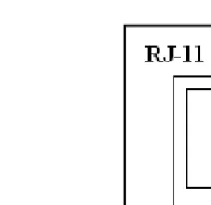
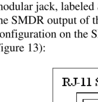
Before you actually connect the INN-FORM XL to the telephone system, make certain that your telephone system SMDR cable pinouts correspond to the INN-FORM XL's SMDR connector. The female RJ11 style modular jack, labeled SMDR is used for connection to the SMDR output of the phone system. The pin configuration on the SMDR port is as follows (see Figure 13):
Figure 13. SMDR RJ-11 Jack
• Pins 2 & 5 are receive SMDR data. Only one should be connected. Recommend: pin 2.
• Pin 3 & 4 are signal ground. Connect signal ground to either. Recommend: pin 3.
• Pin 6 is +8V. Satisfies Data Terminal Ready (DTR), if the phone system requires it.