Copyright to IJIRSET www.ijirset.com 66
Automatic Sun Tracking System Using PSoC
Bhavesh Pandey
1, Anita Agrawal
21B.E.(Hons.), Department of Electrical and Electronics Engineering BITS-Pilani, Goa campus India
2Assistant Professor, Department of Electrical and Electronics Engineering and Instrumentation,BITS-Pilani, Goa campus India
Abstract: Vast amount of energy is available within the core of sun. The energy that is received from sun in an hour is more than that is consumed by us in a year [1]. If human race is able to capture even 1% of the total energy which sun delivers then we can cater the need of our race for decades. Efforts are continuously being made to capture as much energy as we can in order to store most of the energy which se are getting. In this paper a device called solar tracker has been discussed. Solar panels give maximum output when the plane of the solar collector is normal to incident radiations [2]. The system discussed in this paper uses a PSoC device to control a small model of solar tracker. Voltage across the solar panel and a photoresistor is fed as an input to the PSoC to be processed and the output is fed to the geared DC motor.
Keyword: Photovoltaic Cells, Solar Tracker, PSoC (Programmable System on Chip), Efficiency, ADC (Analog to Digital Convertor), MUX (Multiplexer).
I. INTRODUCTION
Solar cells or photovoltaic cells are semiconductor diodes that convertavailable sunlight (at least a portion) into electrical power. They are basically P-N junction photodiodes with very large light-sensitive area [3]. Each photodiode is a solar cell. All these cells are connected inside a module to form a solar panel. These solar panels are cascaded together to form arrays to generate high power electricity[4]. To attain the maximum benefit from these solar panels, we need to position them in the direction that captures most of the energy. This direction depends upon various factors. The panels are mounted at a fixed tilt, but because sun keeps changing its position due to the rotation as well as the revolution of earth, these panels can capture more energy if their tilt is adjusted periodically.
A detailed observation of solar panel in various weather conditions was first carried out. And setting theseobservations as our operating point, we made a set-up around the PSoC platform andcontrolled the direction of solar panel.
II.ADJUSTING THE TILT
Copyright to IJIRSET www.ijirset.com 67
III. SYSTEM DESCRIPTION
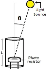
Figure 2 shows the system design. It uses one 3 V solar panel for receiving theinput voltage from the sun. The system works only when the input from the panel is more than a specified value. This value is based on the observation that when sun is shining, what is the minimum voltage we are obtaining from the panel. In our case this voltage is 2.67 V. If the voltage across solar panel is more than 2.67 V, the processor sends the instruction to change the select signal of MUX. This takes the value of voltage across the photo resistor. The photo resistor is in series with a fixed resistor of 3.3 KΩ, connected across a supply of 3.3 V and the whole circuit works as a voltage divider circuit.The photo resistor is housed in a cup work when sun is at specified angle as shown in figure 3. This angle can be changed by changing the length „L‟ of the cup.
Figure 3. Angle of incidence at which photoresistor works Figure 2. System Description
Copyright to IJIRSET www.ijirset.com 68
When there is no incident light on resistor, its resistance is infinite but as this setup is kept in daylight the resistance is not infinite but it is such that (almost) voltage Vcc (3.3V) appears across it. When sunlight falls on it, resistance is decreased and the voltage across it decreases. This is the basic principle behind this photoresistor working as a position sensor for sun.
After changing select line of MUX, the input to the microprocessor is the voltage across photoresistor. It compares the value of this voltage with 2.56 V. This value was also obtained after observation. This is the maximum voltage across resistor when sunlight falls on it. This value can also be adjusted by adjusting the value of the fixed resistance in the circuit. If the voltage is greater than this value, then the processor sends the signal to rotate the panel until it drops below 2.56 V. When both the conditions i.e. voltage across Solar panel is more than 2.67 V and the voltage across photoresistor is less than 2.56 V,are satisfied, then we achieve the maximum output from the solar panel.
Copyright to IJIRSET www.ijirset.com 69
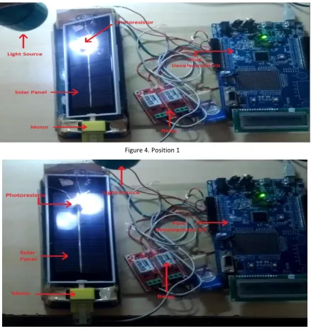
IV. RESULTS
The design was tested using a light source modeled as sun. For this we had to change few values in the code to match with the new light source. Figure 4 and Figure 5 shows the response at two different positions of the light source.The system was working perfectly and the response was same as expected in figure 1.
V. ADVANTAGES
The main advantage of this system is low power consumption. It takes very less power which can be also drived directly from the solar panel or from a DC battery with recharging mechanism. In the evening when sun sets, the solar panel stops rotating and on the next day it has to come to its original position. In other systems, this task is done using another mechanism for retracing back the path during night. But in our system this is achieved by full rotation (≈180º) in the same direction. This consumes almost equal power as it takes in retracing back but it saves the energy which is required to power up the extra circuitry for retrace mechanism. Also the retrace mechanism would require energy during night to retrace but our mechanism becomes active only when sun is present, hence it can always get the power from sun.
Another advantage is that the system is fully automatic. No manual work is needed to switch on or off at any time. The system is very accurate too. The propagation delay is in milliseconds.
VI. LIMITATIONS
(i) The module is designed only for single axis rotation not for dual axis.
(ii) It can’t retrace back its path. Returning back to its original position after the sunset, is done by rotating the panel fully 180 degrees.This consumes more space than the systems which retrace back their path.
VII. FUTURE SCOPE
In future this project can be implemented on large solar plants. We can make the system easier to use by implementing it using a single microcontroller connected with a small module mounted near the larger solar panelsand then sending the information about the change in the angle of tilt from small panel to the larger ones, either using wired or wireless connectionto control the larger ones accordingly. This system is designed to operate continuously. But it can be also designed it to receive the inputs at fixed intervals of time (maybe 4 or 5 minutes). This will also result in reduced power consumption at a great level.
VIII. CONCLUSION
An efficient and low power PSoC based sun tracker had been designed. One microcontroller can be used to control many solar panels; only the correct information needs to be sent. Efficiency is increased almost by the factor of 2. Hence reliable, economical, compact and efficient system of solar energy conversion had been made possible with this design.In a nutshell, the output of this effort is just a small drop in the big ocean of science and technology, in order to make life simpler, easier and enjoyable.
REFERENCES
[1]
NANOCO group PLC,http://www.nanocotechnologies.com/content/CommercialApplications/Solar.aspx
[2] J. Rizk, and Y. Chaiko, “Solar Tracking System: More Efficient Use of Solar Panels”, World Academy of Science,
Engineering and Technology, 41, 2008.
[3] SolarPower
http://www.solar-power-answers.co.uk/basics.php
[4] SolarGreenhttp://www.solargreen.net.au/solarcell.php
Copyright to IJIRSET www.ijirset.com 70
[6] TheerawutJinayim, SomchaiArunrungrasmi, et al. “Highly Efficient Low Power Consumption Tracking Solar Cells
for White LED-Based Lighting System”International journal of electrical, computer, and systems engineering volume 1 number 2 2007 ISSN 1307-5179
[7] João M. G. Figueiredo, José M. G. Sá da Costa, “Intelligent Sun-Tracking System for Efficiency Maximizationof
Photovoltaic Energy Production”.
[8] Siemens http://www.siemens.com/innovation/en/news/2011/solar-panels-track-the-sun-for-more-efficiency.htm
[9] A.B. Afarulrazi, W. M. Utomo, “Solar Tracker Robot using Microcontroller”, 2011, International Conference on
Business, Engineering and Industrial Applications (ICBEIA).
[10] F. Huang, D.Tien, James Or, “A Microcontroller Based Automatic Sun Tracker with a New Solar energy Conversion
Unit”
[11] A.Canova, L.Giaccone, and F. Spertino, “Sun Tracking for Capture Improvement”, 22nd European Photovoltaic Solar
Energy Conference EUPVSEC, WIP Renewable Energies, Milano. 3053-3058, September 2007.
[12] H.D. Mohring, F. Klotz, and H. Gabler, “Energy Yield of PV Tracking Systems”, 21st European Photovoltaic Solar
Energy Conference - EUPVSEC, WIP Renewable Energies, Dresden. 2691-2694, September 2006.
[13] S. Abdallah and S. Nijmeh, “Two-Axis Sun Tracking with PLC Control,” in Energy Conversion and Management, vol.
45, 2004.1931-1939.
[14] A. Yazidil, F. Betin, et al. “Low cost two-axis solar tracker with high precision positioning”.
BIOGRAPHY
Bhavesh Pandey is doing Bachelors of Engineering in Electrical and Electronics Engineering from BITS Pilani K.K. Birla Goa Campus. His interests includes microcontrollers and chip designing.