ISSN (Online) : 2319 - 8753 ISSN (Print) : 2347 - 6710
I
nternationalJ
ournal ofI
nnovativeR
esearch inS
cience,E
ngineering andT
echnologyVolume 3, Special Issue 3, March 2014
2014 International Conference on Innovations in Engineering and Technology (ICIET’14)
On 21st&22ndMarch Organized by
K.L.N. College of Engineering, Madurai, Tamil Nadu, India
ABSTRACT—This paper presents the voltage regulation of hybrid power system with the inter connection of PV system, wind energy conversion system and battery system. The voltage regulation is done with the help of fuzzy logic controller through simulations using MATLAB / SIMULINK. In the proposed system the solar energy and wind energy is combined to produce electrical energy and a battery source is used for charging and discharging of energy. Then power electronic converters are used for the conversion of ac to dc and dc to ac. A PWM inverter is used for the conversion of dc to ac supply. In which a control circuit is designed using fuzzy logic controller for gate signals for the voltage regulation of the hybrid energy system. Then the hybrid energy system is connected to the grid from which the energy is supplied to the loads. The voltage regulation is done for both AC and DC loads.
KEYWORDS— INDEX TERMS—PV, Wind, Battery, PWM Inverter, Fuzzy logic controller.
I. INTRODUCTION
The effective utilization of renewable energy systems is discussed by many authors. The optimal sizing for wind-solar-battery hybrid power system according to the system working ingrid-connected and stand-alone modes is carried out in the system [1]. The renewable energy sources are time dependent and its availability has a daily and seasonal pattern which leadsto difficulties in the regulation of the output power to match-up with the demand [2]. In the distribution system the weakest branches which are found to go to the instability state are selected for DG allocation to maintain voltage stability in the system [3]. The system cost involves investments, replacements and operation and maintenance as well as loss of load costs [4].The whole power distribution system
is designed as a system with controllable converters with the overall system cost and reliability that actually
improve the system performance [5].The developed methodology helps to obtain the optimal number of wind turbines, PV panels and storage units ensuring that the system total cost is minimized while guaranteeing a highly reliable source of load power to the system [6].The Power-flow calculations are carried out in the system to assess the impact of fluctuation of solar irradiance on the grid voltage has to be analyzed in the system [7]. The impacts of a large-scale wind generation on the voltage profile, system operation, and system security have been investigated and studied in the system [8]. The system plan was developed traditionally to achieve a minimum cost objective (MCO) in the system while satisfying the reliability, energy demand, stability and battery constraints in the system. The minimum emissions objective (MEO) is also an important objective to achieve the result to the above mentioned constraints. The above problems can be solved using linear programming which minimizes the two objectives at the same time of a multi-objective problem in the system [9].The ability of energy storage system to increase the penetration of renewable generation on weak electricity grids is predicted and to improve the generation of electricity in the system [10].The generation and storage units for each system are properly sized in order to meet the load demand and minimize the total annual cost in the system [11].A decision support technique will help the decision maker’s to study the factors in the design of a hybrid power system for grid connected applications that relates mainly to social and political conditions, and to the technical advances and economics in the system[12].The isolation and the demand in load are modeled as stochastic variables with the help of historical data and experimentation results respectively [13].The optimal design of a hybrid wind-solar power system for
Modeling Of Grid Connected Hybrid System
With Fuzzy Logic Controller For Voltage
Regulation
P.Loganthurai#1, G.Manikandan#2
#Department of Electrical and Electronics Engineering, K.L.N College of Engineering, Madurai, India.
either autonomous or grid-linked applications in which the analysis employs linear programming techniques to minimize the average production cost of electricity while meeting the load requirements in reliability, and takes the environmental factors into consideration in the design and operation phases [14]. For a given load and a desired loss of power supply probability is based on optimum number of PV modules and batteries were calculated based on the minimum cost of the power system [15].
II. HYBRID POWER SYSTEM
In hybrid power systems, a number of renewable energy generators and storage components are combined to meet the energy demand of the power system. It mainly includes PV generators and wind generators, the others sources of electrical energy can also be added to meet the energy demand. It is essential to know the energy demand and the resources available at that site before developing a hybrid power system. The energy planners must study the availability of solar energy, wind, and other potential resources at that site. This will help them to design what kind of hybrid power system will be suitable to meet the demand. In this paper, a brief technical description of some of the different hybrid power system configurations is considered. It mainly includesPV system, wind energy and battery system to form a hybrid power system as shown in fig. 2.1.
Fig. 2.1 hybrid power system
III.FUZZY LOGICCONTROLLER
The fuzzy inference system is a popular computing framework based on the concept of fuzzy reasoning, fuzzy set theory, and fuzzy if-then rules.
Fig. 3.1: fuzzy logic representation
The fuzzy logic controller (FLC) is used in the fuzzy inference system which consists of a formulation of the mapping from a given input set to an output set. The process of mapping denotes the basis from which the inference or conclusion can be made. The structure of fuzzy inference system comprises of three components namely a rule base, a data base, and a reasoning mechanism. The first component is the rule base that contains a selection of fuzzy rules then the second component is the data base, that defines the membership functions used in the fuzzy rules and the third component is a reasoning mechanism that performs the inference procedure according to the rules to derive a desired output.
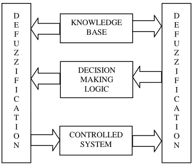
The FLC consists of four components, they are fuzzification interface, knowledge base, decision making logic, and defuzzification interface as shown in fig 3.1.
Fuzzification: In the process of fuzzification, the input variables are fuzzified i.e. it is the conversion of the input data into suitable linguistic values.
Knowledge base: The knowledge base consists of linguistic control rule base anda database. The database provides the necessary definitions, which are used to specify the fuzzy data manipulation andlinguistic control rules in an FLC. By means of set of linguistic control rules the rule base determines the control policy of domain experts.
Decision making logic: It is the capability in which human intelligence is stimulated using human decision making based on fuzzy concepts.
Defuzzification: The defuzzification is the process in which it converts the range of output variables into corresponding universe of discourse, the system is said to be a non-fuzzy logic decision system if the output from the defuzzifier is a control action for a process. There are different techniques for defuzzification such ascentroid method, maximum method, height method etc.
KNOWLEDGE BASE
DECISION MAKING
LOGIC D
E F U Z Z I F I C A T I O N
CONTROLLED SYSTEM
D E F U Z Z I F I C A T I O N
DC/AC GRID AC LOADS
DC LOADS DC/DC
AC/ DC AC/DC
DC/DC BATTERY
SYSTEM WIND ENERGY SYSTEM
IV. DESIGN OF HYBRID POWER SYSTEM
In the proposed system the hybrid power system includes the PV system, the wind energy system, and the battery system
A. PV system:
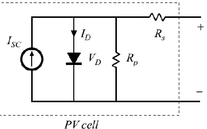
The equivalent circuit of PV cell is shown in fig 4.1 in which a bypass diode is connected across the circuit.
Fig. 4.1: equivalent circuit of PV cell
Where,
𝐼𝑆𝐶= Short circuit current
𝐼𝐷 = Diode current
𝑉𝐷= Diode voltage
𝑅𝑆= Series resistance
𝑅𝑃= Parallel resistance
Applying Kirchhoff's Current Law (KCL) to the above circuit shown in fig. 4.1 we get,
𝐼𝑆𝐶− 𝐼𝐷− 𝑉𝐷
𝑅𝑃− 𝐼𝑃𝑉 = 0 (1) Applying Kirchhoff's Voltage Law (KVL) to the above circuit shown in fig. 4.1 we get,
𝑉𝑃𝑉 = 𝑉𝐷− 𝑅𝑆 (2)
The diode characteristics of the above circuit shown in fig. 4.1 is given by,
𝐼𝐷 = 𝐼𝑜(𝑒𝑉𝐷 𝑉𝑇− 1) (3)
The equation (1), (2), and (3) determines the KCL, KVL and diode characteristics of the equivalent circuit of the PV cell.
Where,
𝐼𝑜= Reverse saturation current of p-n junction.
𝑉𝑇 =Terminal voltage.
𝐼𝑃𝑉 =PV current.
𝑉𝑃𝑉 =PV voltage.
B. Wind Energy System:
The power and torque obtained from the wind turbine is given by,
𝑃𝑇= 1
2𝜌𝐴𝑟𝐶𝑝(𝛽, 𝜆)𝑉𝑊
3 (4)
𝑇𝑇 = 1
2𝜔𝑟𝜌𝐴𝑟𝐶𝑝(𝛽, 𝜆)𝑉𝑊
3 (5)
The equation (4) and (5) determines the power and torque delivered by the wind turbine.
Where,
PT= mechanical power extracted from turbine rotor,
TT= mechanical torque extracted from turbine rotor,
Ar= area covered by the rotor= πR2 where R is turbine
rotor radius [m],
VW= velocity of the wind [m/s],
Cp= performance coefficient (or power coefficient),
ρ = air density [kg/m3],
λ= tip-speed-ratio (TSR), β = rotor blade pitch angle [rad.],
ωT= angular speed of the turbine shaft [rad/s].
The blade tip-speed-ratio of the wind turbine is given by:
𝜆 =𝑏𝑙𝑎𝑑𝑒𝑡𝑖𝑝𝑠𝑝𝑒𝑒𝑑
𝑤𝑖𝑛𝑑𝑠𝑝𝑒𝑒𝑑 = 𝜔𝑇∗𝑅
𝑉𝑊 (6)
The equation (6) determines the blade tip speed ratio of the wind turbine
The power coefficient Cp is related to the tip-speed-ratio λ, and rotor blade pitch angle, β. Cp changes with different values of the pitch angle, but the best efficiency is obtained for β=0. It is assumed that the rotor pitch angle is fixed and equal to zero.
𝐶𝑃 𝜆, 𝛽 = 0.44 − 0.0167𝛽 sin 𝜋 −3+𝜆
15−0.3𝛽 − 0.00184(−3 + 𝜆)𝛽 (7)
The equation (7) determines the power coefficient of the wind turbine with respect to tip-speed-ratio λ, and rotor blade pitch angle, β.
The theoretical upper limit for Cp is 0.59 according to Betz’s Law, but its practical range of variation is 0.2-0.4. The stator and rotor currents are given by
𝑖𝑑𝑠 = 1
𝑥𝑙𝑠(𝜓𝑑𝑠− 𝜓𝑚𝑑) (8)
𝑖𝑞𝑠 = 1
𝑥𝑙𝑠(𝜓𝑞𝑠 − 𝜓𝑚𝑞) (9)
𝑖𝑑𝑟 = 1
𝑥𝑙𝑟(𝜓𝑑𝑟 − 𝜓𝑚𝑑) (10)
𝑖𝑞𝑟 = 1
𝑥𝑙𝑟(𝜓𝑞𝑟− 𝜓𝑚𝑞) (11)
The equation (8), (9), (10) and (11) determines the stator and rotor currents of the induction machine with respect to d-q axis.
The stator and rotor flux linkages are given by
𝑑 𝑑𝑡𝜓𝑞𝑠= 𝐶1
∗𝜓
𝑞𝑠+ 𝐶2∗𝜔𝑒𝜓𝑑𝑠+ 𝐶3∗𝜓𝑞𝑟+ 𝐶4∗𝜓𝑑𝑟𝜔𝑔+ 𝐶5∗𝜔𝑒𝑣𝑞𝑜 (12)
𝑑 𝑑𝑡𝜓𝑑𝑠= 𝐶2
∗𝜔𝑒𝜓𝑞𝑠+ 𝐶1∗𝜓𝑑𝑠− 𝐶4∗𝜓𝑞𝑟𝜔𝑔+ 𝐶3∗𝜓𝑑𝑟+ 𝐶5∗𝜔𝑒𝑣𝑑𝑜
(13)
𝑑
𝑑
𝑑𝑡𝜓𝑑𝑟 = 𝐶3𝜓𝑑𝑠+ 𝜔𝑒−𝜔𝑔 𝜓𝑞𝑟+ 𝐶4𝜓𝑑𝑟 (15) The equation (12), (13), (14) and (15) determines the stator and rotor flux linkages of the induction machine with respect to d-q axis.
C. Battery system:
The kinetic battery model (KiBaM) is adopted here to calculate the amount of energy that can be absorbed by or released from the battery bank at each time step. The KiaBM is based on the concepts of electrochemical kinetics, modeling a battery as a two-tank system. The first tank contains “available energy,” which is readily available for conversion to dc electricity. The second tank contains “bound energy,” which is chemically bound and therefore not immediately available for release.
The available and bound energy (kWh) at each time step are described as
𝑄 = 𝑄1+ 𝑄2 (16)
𝑄1_𝑒𝑛𝑑 = 𝑄1𝑒−𝑘∆𝑡+
𝑄𝑘𝑐 −𝑃𝑏𝑠 (1−𝑒−𝑘∆𝑡)
𝑘 +
𝑐𝑃𝑏𝑠(𝑘∆𝑡−1+𝑒−𝑘∆𝑡)
𝑘 (17)
𝑄2_𝑒𝑛𝑑 = 𝑄2𝑒−𝑘∆𝑡+ 𝑄 1 − 𝑐 1 − 𝑒−𝑘∆𝑡 +
𝑃𝑏𝑠(𝑐−1)(𝑘∆𝑡−1+𝑒−𝑘∆𝑡) 𝑘 (18)
The equation (16), (17) and (18) determines the available energy and bound energy at the beginning and at the end of the time step.
The maximum charge and discharge power at each time step are described as
𝑃𝑏𝑠 _𝑐ℎ𝑚𝑎𝑥 =
𝑘 𝑄1𝑒−𝑘∆𝑡+𝑄𝑘𝑐 (1−𝑒−𝑘∆𝑡)
1−𝑒−𝑘∆𝑡+𝑐(𝑘∆𝑡−1+𝑒−𝑘 ∆𝑡) (19)
𝑃𝑏𝑠 _𝑑𝑐ℎ𝑚𝑎𝑥 =
−𝑘𝑄𝑚𝑎𝑥+𝑘𝑄1𝑒−𝑘∆𝑡+𝑄𝑘𝑐 (1−𝑒−𝑘∆𝑡)
1−𝑒−𝑘∆𝑡+𝑐(𝑘∆𝑡−1+𝑒−𝑘∆𝑡) (20)
The equation (19) and (20) determines the maximum charging and discharging power of the battery system.
D. Energy Management in hybrid power system:
If the total power generated by PV and Wind Power Generation is less than the load demand, the battery will be discharged. The power flow is expressed as shown in equation (21).
𝑃𝐿 𝑡 = 𝑃𝑤𝑡 𝑡 + 𝑃𝑝𝑣 𝑡 + 𝑃𝑏𝑠 _𝑑𝑐ℎ 𝑡 (21)
If the total power generated by PV and WPG is more than the load demand, the excess power will charge the battery. The power flow is expressed as shown in equation (22).
𝑃𝐿 𝑡 = 𝑃𝑤𝑡 𝑡 + 𝑃𝑝𝑣 𝑡 − 𝑃𝑏𝑠 _𝑐ℎ 𝑡 (22)
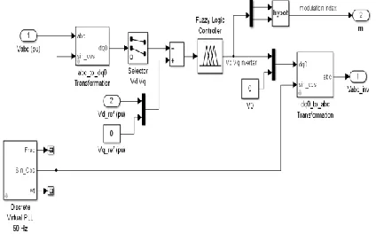
The overall Simulink model of the hybrid power system is shown in fig 4.2.
Fig. 4.2: Simulink model of hybrid power system
The overall Simulink model describes the Simulation diagram of the hybrid system in which PV system, wind energy system and battery systems are connected through a power electronic controller in which it perform DC to DC transformation and AC to DC transformation and it is fed in to the PWM inverterfor AC conversion and the system is connected to the grid and the loads. Here d-axis and q-axis voltages are taken as inputs to the FLC to get the desired dq-axis voltage then it is used to produce gate signals to the PWM inverter in which the voltage regulation is done.
V. DESIGNOFFUZZYLOGIC CONTROLLER
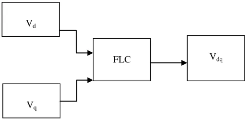
The proposed block diagram of the fuzzy logic controller is given below in which it includes two input variables Vdand Vqfollowed by the fuzzy logic controller
to give the desired d-axis and q-axis voltage Vdq.
Fig. 5.1: block diagram of FLC
In the proposed system, there are two inputs and one output. Here mamdani fuzzy model is used for implementation of fuzzy controller in which centroid method is for defuzzification process.
The first input is d axis voltage(Vd) in which it has five membership functions, the membership functions are negative low(NL), negative high(NH), zero(ZE), positive low(PL), positive high(PH).
The second input is q axis voltage(Vq) in which it has five membership functions, the membership functions are
Vd
Vq
negative low(NL), negative high(NH), zero(ZE), positive low(PL), positive high(PH).
The single output is the dq axis voltage(Vdq) in which it has four membership functions, the membership functions are zero(ZE), low(LW), medium(MD) and high(HG).
From the above mentioned linguistic variables the fuzzy rules are framed according to the conditions using if-then rules and it is mentioned in fuzzy truth table as shown in TABLE I.
TABLE I
Fuzzy truth table
Vd\Vq NL NH ZE PL PH
NL LW MD LW LW MD
NH MD HG MD MD HG
ZE LW MD ZE LW MD
PL MD MD LW MD HG
PH MD HG MD MD HG
VI. CONTROL CIRCUIT FOR VOLTAGE REGULATION
In the voltage regulation of the hybrid power system, a control circuit is designed in the system. The fuzzy logic controller is included in the control circuit to get the desired output in the hybrid power system as shown in fig. 6.1.
Fig. 6.1: control circuit with FLC
In the above control circuit, the gate signal is produced and it is given to the PWM inverter for voltage regulation of the system. Here in the input side abc to dqo transformation is done and the d axis and q axis voltage is fed in to the fuzzy logic controller and in the output side dqo to abc transformation is done and these transformation is known as Clarke and Parks transformations. A Phase-Locked Loop (PLL) is an electronic circuit with voltage or current driven oscillator that is adjusted constantly to match in phase the frequency of an input signal and hence voltage regulation is obtained from the circuit.
VII. RESULT AND DISCUSSIONS
The voltage regulation is done for both AC loads and DC loads using fuzzy logic controller and the output waveform are given below, in the output waveform the voltage, current, and power waveforms are displayed and the outputs are analyzed to determine the voltage regulation of the hybrid power system.
Fig. 7.1: output waveform of load voltage for AC load
The above fig. 7.1 describes the output waveform of the load voltage for AC load in which output load voltage is regulated to provide uniform supply to the utility.
Fig. 7.2: output waveform of load current for AC load
The above fig. 7.2 describes the output waveform of the load current for AC load in which output load current is regulated to provide uniform supply to the utility.
The voltage and current waveform for AC load is represented in the above figure. Analyzing the output waveform, we have obtained the voltage regulation for AC load in the given system as shown in fig 7.1.
Fig. 7.3: output waveform of load voltage for DC load
L
o
ad
v
o
ltag
e
(v
)
TIME (sec)
L
o
ad
cu
rr
en
t (
A)
TIME (sec)
L
o
ad
v
o
ltag
e
(v
)
The above fig. 7.3 describes the output waveform of the load voltage for DC load in which output load voltage is regulated to provide uniform supply to the utility.
Fig. 7.4: output waveform of load current for DC load
The above fig. 7.4 describes the output waveform of the load current for DC load in which output load current is regulated to provide uniform supply to the utility.
The voltage and current waveform for DC load is represented in the above figure. Analyzing the output waveform, we have obtained the voltage regulation for DC load in the given system as shown in fig 7.3.
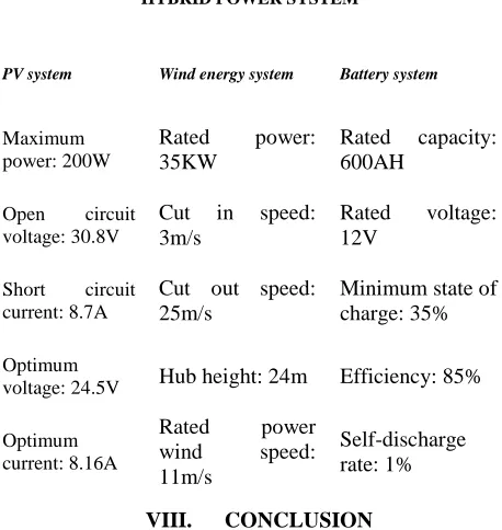
TABLE2
PARAMETERSOFHYBRIDPOWERSYSTEM
HYBRID POWER SYSTEM
PV system Wind energy system Battery system
Maximum power: 200W
Rated power: 35KW
Rated capacity: 600AH
Open circuit voltage: 30.8V
Cut in speed: 3m/s
Rated voltage: 12V
Short circuit current: 8.7A
Cut out speed: 25m/s
Minimum state of charge: 35%
Optimum
voltage: 24.5V Hub height: 24m Efficiency: 85%
Optimum current: 8.16A
Rated power wind speed: 11m/s
Self-discharge rate: 1%
VIII. CONCLUSION
The modeling and simulation of hybrid power system with fuzzy logic controller has been demonstrated for voltage regulation of the system in which the issues in varying nature of the renewable energy sources are considered in the system. The fuzzy logic controller is designed with the help of MATLAB / SIMULINK in which the d axis and q axis voltage is given as input the fuzzy logic controller and the output dq axis voltage is used for generating pulses for the gate signal of PWM
inverter for regulation of voltage in the system. The voltage regulation is verified for AC and DC loads in the hybrid power system
ACKNOWLEDGMENT
The authors are grateful to the principal and management of K.L.N college of Engineering, Madurai for providing all facilities for the research work.
REFERENCES
[1] Lin Xu; XinboRuan; Chengxiong Mao; Buhan Zhang; Yi Luo, "An Improved Optimal Sizing Method for Wind-Solar-Battery Hybrid Power System," Sustainable Energy, IEEE Transactions, vol.4, no.3, pp.774,785, July 2013.
[2] Nagaraj, R., "Renewable energy based small hybrid power system for desalination applications in remote locations," Power Electronics (IICPE), 2012 IEEE 5th India International Conference, vol., no., pp.1, 5, 6-8 Dec. 2012
[3] Abdel-Akher, M.; Ali, A. A.; Eid, A.M.; El-Kishky, H., "Optimal size and location of distributed generation unit for voltage stability enhancement," Energy Conversion Congress and Exposition (ECCE), 2011 IEEE , vol., no., pp.104,108, 17-22 Sept. 2011. [4] Ardakani, F.J.; Riahy, G.; Abedi, M., "Optimal sizing of a
grid-connected hybrid system for north-west of Iran-case study," Environment and Electrical Engineering (EEEIC), 2010 9th International Conference, vol., no., pp.29, 32, 16-19 May 2010. [5] Boroyevich, D.; Cvetkovic, I.; Dong Dong; Burgos, R.; Fei Wang;
Lee, F., "Future electronic power distribution systems a contemplative view," Optimization of Electrical and Electronic Equipment (OPTIM), 2010 12th International Conference on , vol., no., pp.1369,1380, 20-22 May 2010.
[6] Menniti, Daniele; Pinnarelli, Anna; Sorrentino, Nicola, "A method to improve micro grid reliability by optimal sizing PV/Wind plants and storage systems," Electricity Distribution - Part 1, 2009. CIRED 2009.20th International Conference and Exhibition, vol., no., pp.1, 4, 8-11 June 2009.
[7] Woyte, A.; Van Thong, Vu; Belmans, R.; Nijs, J., "Voltage fluctuations on distribution level introduced by photovoltaic systems," Energy Conversion, IEEE Transactions, vol.21, no.1, pp.202,209, March 2006.
[8] Chompoo-inwai, C.; Wei-Jen Lee; Fuangfoo, P.; Williams, M.; Liao, J.R., "System impact study for the interconnection of wind generation and utility system," Industry Applications, IEEE Transactions, vol.41, no.1, pp.163,168, Jan.-Feb. 2005.
[9] Chedid, R.; Karaki, S.; Rifai, A., "A multi-objective design methodology for hybrid renewable energy systems," Power Tech, 2005 IEEE Russia , vol., no., pp.1, 6, 27-30 June 2005.
[10] Barton, J.P.; Infield, D.G., "Energy storage and its use with intermittent renewable energy," Energy Conversion, IEEE Transactions, vol.19, no.2, pp.441, 448, June 2004.
[11] Kellogg, W. D.; Nehrir, M.H.; Venkataramanan, G.; Gerez, V., "Generation unit sizing and cost analysis for stand-alone wind, photovoltaic, and hybrid wind/PV systems," Energy Conversion, IEEE Transactions, vol.13, no.1, pp.70, 75, Mar 1998.
[12] Chedid, R.; Akiki, H.; Rahman, S., "A decision support technique for the design of hybrid solar-wind power systems," Energy Conversion, IEEE Transactions, vol.13, no.1, pp.76, 83, Mar 1998. [13] Shrestha, G.B.; Goel, L., "A study on optimal sizing of stand-alone
photovoltaic stations," Energy Conversion, IEEE Transactions, vol.13, no.4, pp.373, 378, Dec 1998.
[14] Chedid, R.; Rahman, S., "Unit sizing and control of hybrid wind-solar power systems," Energy Conversion, IEEE Transactions, vol.12, no.1, pp.79, 85, Mar 1997.
[15] Borowy, B.S.; Salameh, Z.M., "Methodology for optimally sizing the combination of a battery bank and PV array in a wind/PV hybrid system," Energy Conversion, IEEE Transactions, vol.11, no.2, pp.367, 375, Jun 1996.
L
o
ad
cu
rr
en
t (
A)