Companding Techniques using SysGen
Sheetal Patil 1, Satheesh Rao2, D Saravanan3
M.Tech Student, Dept. of Electronics and Communication Engineering, NMAMIT, Nitte, Karnataka, India 1
Assistant Professor, Dept. of Electronics and Communication Engineering, NMAMIT, Nitte, Karnataka, India2
Scientist ‘F’, Centre for Air Borne Systems-DRDO, Bengaluru, Karnataka, India3
ABSTRACT: Although humans are well equipped for analog communications, analog transmission is not particularly efficient. Digital signals, having only "one-bit" and "zero-bit" states, are more easily separated from noise. It can be amplified without corruption but are more prone to noise and data loss on long distance communications. The world's communication systems have converted to a digital transmission format called pulse code modulation (PCM). PCM is called "waveform" coding because it creates a coded form of the original voice waveform. It is defined in the ITU-T G.711 specification. Since most voice signals generated have noise, to improve voice quality companding is used.
KEYWORDS: Companding, PCM, ITU-T, SysGen.
I. INTRODUCTION
Companding refers to the process of first compressing an analog signal at the source, and then expanding this signal back to its original size when it reaches its destination. The term companding is created by combining the two terms, compressing and expanding, into one word. At the time of the companding process, input analog signal samples are compressed into logarithmic segments. Each segment is then quantized and coded using uniform quantization. The compression process is logarithmic. The compression increases as the sample signals increase. By companding many advantages can be achieved, such as improved noise treatment. In order to prevent the signal from distortions caused by channel these techniques are used. The ITU-T standards for companding are called A-Law and μ-Law.
A-Law and μ-Law Companding
A-Law and μ-Law are audio compression schemes (codecs) defined by Consultative Committee for International Telephony and Telegraphy (CCITT) G.711 which compress 16-bit linear PCM data down to eight bits of logarithmic data. They convert 16 bit digital audi o signal into 8 bits by a logarithmic formula.
A-Law Companding
Across Europe the CCITT suggested A-Law as standard companding technique. The linear sample values are restricted to 12 magnitude bits and the A-Law compression can be more precisely explained by the equation (1), the parameter used for compression is A i.e A=87.7 in Europe and y is the normalized int eger to be compressed. ( )= ( ∗| |) ( ) , ≤ | |≤ ( ( | |)∗( ( )) ( ( )) , ( )≤ | | ≤ (1)
μ-Law Companding
The United States and Japan use μ-Law companding. The linear sample values are restricted to 13 magnitude bits and
the μ-Law compression can more precisely be explained by equation (2), the parameter used for compression is µ i.e µ=255 and z is the normalized integer to be compressed.
F(x) = ( ( )∗( ( | |)))
( ( )) , ≤| |≤ (2)
After encoding the input data, an inversion pattern is applied to the obtained result which is of 8-bit to increase the density of transitions which is a benefit to hardware performance and the decoded output is obtained. The decoding is done by xoring the 8-bit code with 0xFF.
II. LITERATURE SURVEY
Charles.W.Brokish made a report of companding techniques which are A-Law and μ-Law and explained the same in brief [1]. Arazi et al., proposed an efficient compander design which converts 20 bit data to 8 bit with 1000 gates using Xilinx Virtex –II Pro FPGA device [2]. A.klein et al., explains how to instantaneously compand the signals using Matlab/Simulink [3].
III. METHODOLOGY
The audio signal is given as input to the Encoder and decoded back through Decoder. The audio input given is “M1F1-int16-AFsp.wav”. It has samples of around 11234 when it was read using audioread command. First for the reference Matlab codes are written for both algorithms. Then using the reference code System Generator blocks where implemented. The System Generator has many inbuilt logical blocks and there are some blocks which cannot be implemented by it directly. So those codes are written in Matlab as function and made as Mcodes.The A-Law and μ -Law use System Generator to implement the Matlab code in blocks.
IV. EXPERIMENTAL SETUP
A-Law implementation using System Generator
The A-Law involves an Encoder and a Decoder. The samples of the audio file, “M1F1-int16-AFsp.wav” is sent to Encoder and the output is obtained at the Decoder.
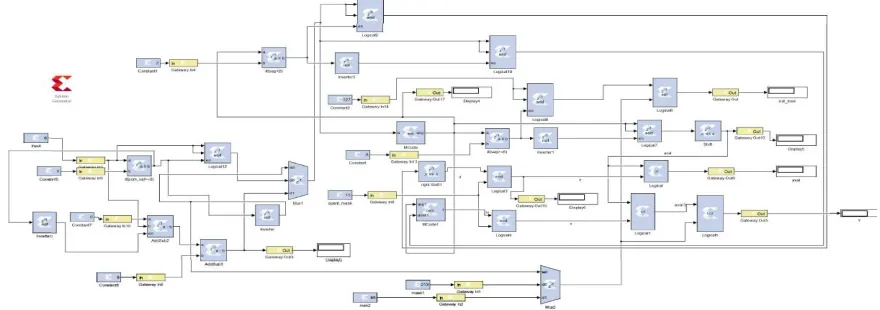
A-Law Encoder
A-Law Decoder
The A-Law Decoder implementation is shown in Figure.2. The Encoder output is fed as input to Decoder block.
Figure 2: A-Law Decoder implementation using System Generator.
μ-Law Encoder and Decoder
The μ-Law also involves Encoder and Decoder whose blocks are implemented using System Generator.
µ-Law Encoder
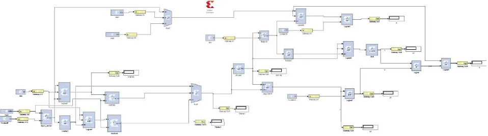
The μ-Law Encoder’s System Generator block is implemented as shown in Figure 3. The audio file samples are given as input Encoder.
µ-Law Decoder
The μ-Law Decoder implementation is given below in Figure 4. The Encoder output is fed as input to Decoder block.
Figure 4: μ-Law Decoder implementation using System Generator.
IV. RESULT AND DISCUSSION
The results consist of A-Law and μ-Law implementation using System Generator in the Simulink.
A-Law implementation using System Generator
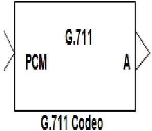
The Simulink has Available System Generator block of G.711 A-Law and μ-Law to which the 16 bit audio file samples are given and the output is noted. The Available System Generator block of G.711 cannot be converted into VHDL code. So these algorithms (A-Law and μ-Law) are implemented using the System Generator blocks which include Mcode and logical blocks that help in implementation of algorithms easily. The inbuilt block is shown in Figure 5.
Figure 5: Available block in System Generator
A-Law Decoder Output
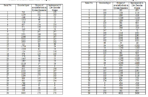
The encoder output is given as input to the decoder. In Table 2 the output of Available block in System Generator and implemented A-Law Outputs are compared.
Table 1 A-Law Encoder Output Table 2 A-Law Decoder Output
μ-Law implementation using System Generator
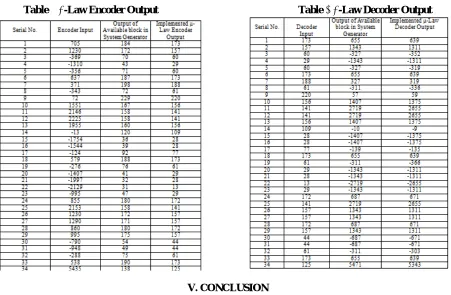
μ-Law Encoder Output
The audio samples which are obtained is given as input to Encoder. In Table 3 the output of Available block in System Generator and implemented μ -Law Outputs are compared.
μ- Law Decoder Output
The Encoder output is given as input to the Decoder. In the Table 4.4, the Available System Generator block and System Generator outputs are compared. The Simulink has an Available System Generator block of G.711 A-Law and
Table 3 μ-Law Encoder Output Table 4 μ-Law Decoder Output
V. CONCLUSION
The audio companding helps in increasing the Signal to Noise Ratio (SNR) by suppressing the noisy data. The outputs of the Available System Generator block and the implemented System Generator are compared and are almost same. The Encoder and Decoder table depict that the signal sent as input to Encoder and the output derived from the Decoder are approximately equal. The audio companding is employed as a basic building block in the hardware module of ADMS.
REFERENCES
[1] Charles.W.Brokish, “A law and μ law Companding using the TMS320C54X”, Application Report SPRA163a, Texas Instruments, 1997. [2] Arazi, Elhanany, “A scalable architecture for high speed digital companding”, 48th IEEE International Midwest Symposium on Circuits and Systems, Vol.1, pp. 488 – 490, 2005.