Study Dynamic Regime of a Electromagnet
Using Finite Element Method
Horgos Mircea1 – Erdei Zoltan2 –Barz Cristian3
Associate Professor PhD, Department of Electrical Engineering, Electronics and Computers, Tehnical University of
Cluj Napoca, North University Center of Baia Mare1
Lecturer PhD, Department of Electrical Engineering, Electronics and Computers, Tehnical University of Cluj Napoca,
North University Center of Baia Mare2
Lecturer PhD, Department of Electrical Engineering, Electronics and Computers, Tehnical University of Cluj Napoca,
North University Center of Baia Mare3
ABSTRACT:Dynamic regime of an electromagnet can be studied using the finite element method. In this work were studied using several variants of electromagnets that generate vibrations using ferromagnetic materials of superior quality. Highlighting the main indices qualitative dynamic regime can be achieved most conveniently about graphics using calculation methods based on the theory of finite elements.
KEYWORDS:dynamic regime, electromagnet, attraction force, FEM analysis.
I. INTRODUCTION
In the electromagnets design is required to know the force of attraction developed by the main types of electromagnets. For two polar parts delimitated by two parallel surfaces each with aria A, located at the distance of one another, in the presence of a constant magnetic field H in the direction of the air gap, the magnetic energy formula is:
, 2
B H A
wM (1)
by using, the theorem of general forces, Maxwell’s equations for attraction force F produce by an electromagnet is:
, 2 2
2 0
2
0 2
A A
B A
H B dS
d F
(2)
considering:
,
m
m R
U H
H B
(3)
we can write the next formula:
, 2 1 2
1 2
d
d U d
dU
F m m
(4)
Where: Umis magnetic voltage between the polar surfaces,
Rm – magnetic reluctance of air gap,
– permeance of the same area, defined as inverse of reluctance.
For the electromagnets with a single excitation circuit, the formula of magnetic energy using inductivity is:
, 2 1 2
2
Li i
according to the theorem of general forces, we obtain the formula for the attraction force: . 2 1 2 d dL i
F (6)
Thus, for the calculation of the attraction force produced by an electromagnet is necessary to determine the magnetic flux, the magnetic induction inside the air gap, the inductivity, the magnetic reluctance and permeance.
II. THE CALCULATION OF THE ATTRACTION FORCE DEVELOPED BY THE MAIN TYPES OF ELECTROMAGNETS
Knowing the value of the flux, inductivity or permeance of an electromagnet we can determine the attraction force produced by the electromagnet by using one of the formulae (2), (4) or (6).
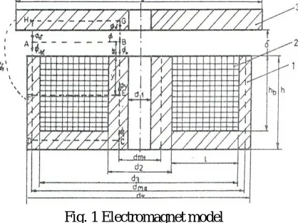
Fig. 1 Electromagnet model
For example, the mantel electromagnet from fig. 1, considering formulae (6), and other general equations, the attraction force can be written:
22
2 2
2 ( )
1 2 1 ) ( 2 1 i N p sh p i N p sh
F
(7) if we ignore the dispersion (λ→0 and p→0), we obtain:
. 2 1 2 Ni F (8)
For the mantel electromagnet from fig. 1, which has the height hb of the window much smaller than its width l, according to (6) and (7) the force has the formula:
. 12 ) ( 2 1 2 2 2 b h h d p sh Ni F (9)We notice that if hbis bigger, then equation (9) becomes equation (7), thus being a general form for it.
III. THE CALCULATION OF MAGNETIC FIELD USING NUMERICAL METHODES
Numerical methods, in comparison with analytical methods, present a bigger application area, having fewer restrictions. This methods lead to acceptable results if certain quality and convergence criteria are maintained.
- linear and homogeneous medium ;
- stationary regime;
- solenation is uniform distributed on the entire section of the coil(J=const.)
In our study, we use MagNet software for the numerical field analyses of electromagnetic vibrator. This allows calculating the magnetic field and also other electromechanical parameters (fluxes, forces, moments, etc.) using finite element method.
FEM has two aspects that have to be treated with great attention, because they can cause important errors:
Boundary conditions: any type of analysis implies an infinite domain, impossible to study with FEM, so is required a restriction through closed surfaces and to enforce some boundaries conditions which gives as results close to the real ones.
Discreteness: The implementation of the nodes and finite elements net, from geometric point of view and of rank of interpolating polynomial, to describe correctly the behavior of the magnetic field in the analyzed domain is the most complex part of an FEM analysis. For an element the magnetic induction is described as a polynomial function of rank smaller with one unit then the rank of the interpolating polynomial, thus is necessary to have more nods and/or to increase their rank. The software creates automatically the net depending on the parameters we want to calculate.
IV. RESULTS OBTAIN WITH FEM ANALYSIS
The base configuration of the electromagnet from (fig. 2) is formed from active materials electro technical steel plate cold laminated CR 1010, for columns, fixed and mobile parts of the electromagnet, and electro technical copper with the conductivity σ = 5,77 * 107 S/m for coils.
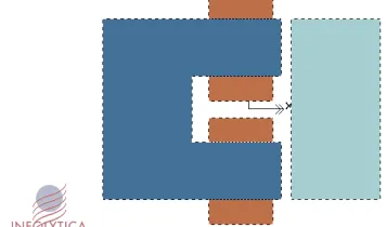
Fig. 2 Base configuration of an electromagnetic
The configuration of other models is identical with the base configuration only that the material for the magnetic circuit was changed with other types of ferromagnetic materials.
To study and to calculate the force produced by an electromagnet there are five configurations, in each of them the magnetic circuit is composed by the following materials: CR 1010 for the base configuration, M19 for model number two , A1 9 for model number three , L800 another ferromagnetic material for the fourth model and for the last model the TR 52 material was used .The characteristics of the magnetization curve for all these materials are given in MagNet software.
Each of the configurations described above were analyzed with FEM method through the package of software for the analysis of electromagnetic field, named InfolyticaMagNet version 6.11.
The analysis are completed ignoring the hysteresis effect of the magnetic material , its behavior corresponding to the magnetization curve and with the next values for the current through the windings : 0.1, 0.2, 0.3, 0.4, 0.5, 0.6, 0.7, 0.8, 0.9, 1, 2, 3, 4, 5 A , which gives us the electrical charges of our electromagnet.
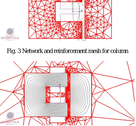
Such analysis was reached polynomial interpolation of the second order and a refinement of the mesh on the geometry of the electromagnet as shown in Figures 3 and 4. In Fig. 3 it is playing a mesh for column yoke and armature, and in Fig.4 the air-gap network is shown with a refining (thickening network) as good soles polar opposite.
Fig. 3 Network and reinforcement mesh for column
Fig.4 Mesh network of gap
For each model of study were conceived twelve problems to calculate the magnetic field , having as a parameter the dimension of the air gap , with values which grow by 0.5 mm from 0.5 mm to 6 mm.
In the followings are presented the results of an FEM analysis given by InfolyticaMagNet software, version 6.11.
Fig. 4 The force characteristic for CR 10 and for a 1 A current
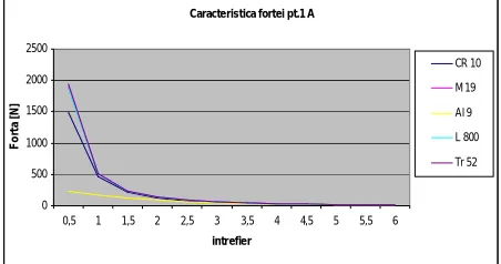
After analyzing all the models and obtaining the numerical results for each model, were able to draw a family of curves with force characteristic for all configurations. Thus a comparative analysis was made for all the force characteristics depending on the size of air gap.
The charts below will be played characteristic strength for the five types of materials and windings current values of 0.1, 0.5, 1, 2, 3, 4, 5 A, carrying electrical charges of the electromagnet.
Fig. 5 The force characteristic for a 0.1 A current
Fig. 6 The force characteristic for a 0.5 A current
Fig. 7 The force characteristic for a 1 A current
Caracter istica for tei pt. 0.1 A
0 5 10 15 20 25
0,5 1 1,5 2 2,5 3 3,5 4 4,5 5 5,5 6
intrefier
F
o
rt
a
[
N
]
CR 10
M 19
Al 9
Al9-CR10
Caracter istica for tei pt. 0.5 A
0 100 200 300 400 500 600
0,5 1 1,5 2 2,5 3 3,5 4 4,5 5 5,5 6
intrefier
F
o
rt
a
[
N
]
CR 10
M 19
Al 9
Al9-CR10
Caracte ristica fortei pt.1 A
0 500 1000 1500 2000 2500
0,5 1 1,5 2 2,5 3 3,5 4 4,5 5 5,5 6
intr efie r
F
o
rt
a
[
N
]
Fig. 8 The force characteristic for a 2 A current
Fig. 9 The force characteristic for a 3 A current
Fig. 10 The force characteristic for a 4 A current
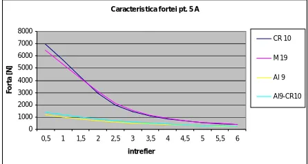
Fig. 11 The force characteristic for a 5 A current
Caracteristica fortei pt. 2 A
0 500 1000 1500 2000 2500 3000 3500 4000 4500 5000
0,5 1 1,5 2 2,5 3 3,5 4 4,5 5 5,5 6
intrefier
F
o
rt
a
[
N
]
CR 10
M 19
Al 9
Al9-CR10
Caracte ris tica forte i pt. 3 A
0 1000 2000 3000 4000 5000 6000 7000
0,5 1 1,5 2 2,5 3 3,5 4 4,5 5 5,5 6
intrefie r
F
o
rt
a
[
N
]
CR 10
M 19
Al 9
Al9-CR10
Caracteristica fortei pt. 4 A
0 1000 2000 3000 4000 5000 6000 7000
0,5 1 1,5 2 2,5 3 3,5 4 4,5 5 5,5 6
intrefier
F
o
rt
a
[
N
]
CR 10
M 19
Al 9
Al9-CR10
Caracteristica fortei pt. 5 A
0 1000 2000 3000 4000 5000 6000 7000 8000
0,5 1 1,5 2 2,5 3 3,5 4 4,5 5 5,5 6
intrefier
F
o
rt
a
[
N
]
CR 10
M 19
Al 9
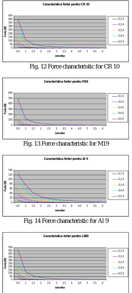
Also, we presented the variations charts of the force depending of the air gap for each type of material having as parameter the current passing through the coils. In the below charts are given for each type of material the force characteristic with the value of the current between 0.1-0.5 A.
Fig. 12 Force characteristic for CR 10
Fig. 13 Force characteristic for M19
Fig. 14 Force characteristic for Al 9
Fig. 15 Force characteristic for L 800
Caracteristica fortei pentru CR 10
0 50 100 150 200 250 300 350 400 450
0,5 1 1,5 2 2,5 3 3,5 4 4,5 5 5,5 6
intrefier
F
o
rt
a
[
N
]
0,1 A 0,2 A 0,3 A 0,4 A 0,5 A
Caracteristica fortei pentru M19
0 100 200 300 400 500 600
0,5 1 1,5 2 2,5 3 3,5 4 4,5 5 5,5 6
intrefier
F
o
rt
a
[
N
]
0,1 A 0,2 A 0,3 A 0,4 A 0,5 A
Caracteristica fortei pentru Al 9
0 20 40 60 80 100 120 140
0,5 1 1,5 2 2,5 3 3,5 4 4,5 5 5,5 6
intrefier
F
o
rt
a
[
N
]
0,1 A 0,2 A 0,3 A 0,4 A 0,5 A
Caracteristica fortei pentru L800
0 50 100 150 200 250 300 350 400 450 500
0,5 1 1,5 2 2,5 3 3,5 4 4,5 5 5,5 6
intrefier
F
o
rt
a
[
N
]
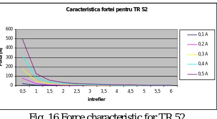
Fig. 16 Force characteristic for TR 52
Possibilities "linearization magnetic materials" exposed to heavy electric medium and large, is relatively low, due to saturation, correction model by coefficients having a degree of generality rather narrow and accuracies less controllable, it is necessary as a way of solving problems field nonlinear numerical analysis.
The major disadvantage of numerical analysis of several independent parameters, to the emergence of solutions to discrete representations, namely values that should be attached unequivocally parameter values that led to these values. With the increasing number of parameters expressing the solution appears increasingly difficult fields with continuous appearance (small intervals of change in parameters).
A case is the study, which analyzes several models in which order to avoid a solution impossible appreciated as behavior of the variation of parameters considered, it was conducted on areas of variation thereof selected, namely such that to cover the ranges of optimal in accordance with current technology and materials.
V. CONCLUSIONS
After making a comparative analysis between the force characteristics we observe the following:
- by using ferromagnetic materials with superior quality we can obtain better values of the force developed by an electromagnet ;
- the value of the force produced by electromagnetic vibration generators will depend mostly of the electrical charges from the vibrator
- by using a combination of magnetic and ferromagnetic materials for the construction of the magnetic circuit we can obtain smaller vibrations of the force within the air gap , but the value of force produced will also be smaller than the case when we used high quality electro technical materials
- the parameters of the dynamic regime of an electromagnet , variable in time , independent or associated , are : current , flux , attraction force , movement of air gap , ( air gap ) , speed and acceleration of this movement ;
- the quality evidence of these parameters is made the most comfortable using graphic presentations from the methods based on FEM
REFERENCES
[1] Darie, S., (1987), Vibratoareelectrice, EdituraTehnica, Bucuresti, 1987
[2] Harris, C.M., (1996), Schock and Vibration Handbook, Fourth Edition, McGraw-Hill Book Company, New York, 1996
[3] Horgos, M., Banica, M., Stoicovici, I. D., (2006), Mathematical model for establishing the vibrating conditions specific to electromagnetic
sieves, The International Conference of the Carpathian Euro Region Specialists in Industrial Systems, 6th edition , Baia Mare, p. 171 – 176
[4] Horgos, M., Neamt, L., Chiver, O., Erdei, Z., (2007), Contributions to the calculation of the force developed by the electromagnets using FEM,
7th International multidisciplinary conference,Baia Mare, May 17-18, Scientific Bulletin Series C: Fascicle Mechanics,ISSN 1224-3264, p. 273-278
[5] Peter, D.C., Micu, E., Petrean, L., (2001), Evalution of magnetic forces in a magnetic separator with permanent magnets, Proceedings of 9th
Balkan Mineral Processing Congress, Istanbul, 2001, p. 97 – 100
[6] Petrean, L., Micu, E., Peter, D.C., (2004), Gradient magnetic force estimation for pole shoe profiles construction in magnetic separators, Proceedings of OPTIM 2004, Vol. I, Brasov, 2004, p. 93-96
[7] Schilling, R. J., Harris, L. S., (1999), Applied numerical methods for engineers using Matlab and C. Brooks and Cole Publishing Company,
USA, 1999
[8] [***] An introduction for Infolyitica Magnet 6.11.
Caracteristica fortei pentru TR 52
0 100 200 300 400 500 600
0,5 1 1,5 2 2,5 3 3,5 4 4,5 5 5,5 6
intrefier
F
o
rt
a
[
N
]