MIMO Scheduling in Fourth Generation
Using Greedy Algorithm for Multi-User
Cellular Transmission
Vijayalakshmi A
1, Rathika M
[2PG Scholar, Dept. o f ECE, Kingston Engineering Co llege, Ve llore, Ta mil Nadu, India1 Assistant Professor, Dept. of ECE, Kingston Engineering College, Vellore , Ta mil Nadu, India2
ABSTRACT: Mult i-user MIMO scheduling in the 3GPP LTE-Advanced cellula r uplink is considered. The uplink allo ws for preceded mult istream t ransmission fro m scheduled user and it can be assigning the same time -frequency resource. Based on some practica l constrains exp loting these features is a challenging to maintain a lo w signalling overhead. The scheduling problem in 3GPP LTE-A cellula r uplink is NP-hard, it can be compose as the ma ximization of the submodular set function to matroid and mult iple ruc ksack constraints. so then we propose Constant factor polynomia l-t ime appro ximat ion algorithms and performance are de monstrated in s imulat ions.
KEY WORDS: Ruc ksack, mu ltiuser scheduling, matroid, NP -hard, resource allocation, submodular ma ximizat ion.
I. I
NTRODUCTIONLTE is the process to generate interface by the 3rd Generation Partnership Pro ject[1]. The 3GPP LTE-A and the IEEE802.11 are the two cellular networks classified as the 4G cellular networks. LTE co mmonly marketed as 4GLTE is a standard wire less communication for high speed data for mobile phones and data termina ls. LTE [as specified in the 3GPP release 8 and 9 docu ment series does not satisfy the technical require the 3GPP consortium has adopted for its new LTE Advanced standard. The ma in require ments for the new access network are high spectral efficiency, high peak data rates, short sound trip time as well as fle xib ility in frequency and bandwidth. The goal of LTE was to increase the capacity and speed of wireless data networks. The 4G uplin k supports the spectral efficiency of15 bps/HZ and the cell average spectral effic iency of 2bps/HZ, u ltra -low latency and the bandwidth of up to 100M HZ.
In order to attain aggressive stipulation, the 3GPP LTE-A uplink is based on the mutated form of orthogonal frequency-division multip le xing based mult iple access. OFDMA is a mu lti -user version of the popular OFDM d igital modulation scheme. Mult iple access is achieved in OFDMA by assigning subsets of subcarriers to individual users. MIMO uses multip le transmitter and receivers that modulated with OFDMA[1]. It allows preceded multistream transmission from each scheduled user. OFDMA allo ws spectral effic iency gains via channel dependent frequency domain scheduling. In this paper the target is on the 3GPP LTE-A uplink and MU MIMO scheduling for the LTE-a UL. The 4G ce llula r system that will be e xpand on the 3GPP LTE-A standard. The frequency domain scheduling is done in the LTE-A UL[2]. The scheduler assigns one or more resource blocks to each scheduled user.
To design practical uplink MU-M IMO resource allocation algorith m for the LTE-A cellu lar networks. The layout of resource allocation along we ighted sum rate utility ma ximization fo r finite user queues and finite precoding codebooks. The user rates are in forced to lie in basic achievable rate of multip le access channel and represents the NP -hard problem in resource allocation. The resource allocation problem can be formu lated as the Rucksack constraints, and solved by polynomia l time randomized constant factor approximation algorith m. In this we used greedy algorithm and it yields a constant factor algorith m[11-14].
II. RELATED WORK
1.MU-MIMOSCHEDULING: Recognize a single -cell uplink a long k users and one base station (BS) wh ich is pretended to have Nr≥1 receive antennas. Users k has𝑁𝑡≥1 trans mit antennas and its power budget is𝑃𝑘. N denote the
total number of resource blocks available (RBs). We infer each RB to have unit size.𝐻𝐾(𝑛) denote the 𝑁𝑟× 𝑁𝑡 channel
matrix seen by the BS fro m user k on RB n whichever we assume is known perfectly to the BS. We certify e=(u ,c ,W) signify a 3-tuple,where 1≤u≤k denotes a user, W 𝜀 𝑤(such that tr (𝑤+𝑤)=1) indicates a precoder fro m a codebook
which is fin ite W and C 𝜀 𝐶that is a valid assignment of RBs Selected fro m the set c which contains all probable valid assignments. Especially each c is an N-length vector with binary valued {0,1} entries and an RB i belongs to c {i e c} if c contains one in its 𝑖𝑡ℎ position,i.e.., c(i)=1.The ground set of all possible such 3-tuples.
e = (u , c, W) = 𝑐𝑒= c, We = W,
𝑢𝑒= u, 𝐻𝑒 𝑛
= 𝐻𝑢(𝑛)∀ 𝑛.
The base station, which has been selected or scheduled by a subset a A< 𝜀 .Base station can be modeled as the output of MIMO mu ltip le access channel by receiving the signal vector fro m each resource block.
𝑦(𝑛)= 𝑐 𝑒
𝑒 ∈𝐴 (n) 𝐻𝑒𝑛 𝑊𝑒 (𝑛)
𝑋𝑒(𝑛)+𝑣(𝑛)
Ma x 1 ≤𝑘 ≤𝐾∝𝑘𝑟𝑘
Where ∝𝑘>0, 1≤ 𝑘 ≤ 𝐾
represents the positive weight of 𝐾𝑡ℎ user.
Fig.1.RB A llocation in the LTE-A UL: The assignment of RBs to each user is represented by a shaded region. Where 𝑣(𝑛)~CN(0,I) is the additive Gaussian noise and 𝑋𝑒(𝑛) is the input vector corresponding to 3-tuple e. The input vector transmitted by user 𝑢𝑒 on RB n.
2. Two chunks per -user:
To form at-most two non-contiguous chunks ,each scheduled users assigned a set of resource blocks. A set of contiguous resource blocks is a chunks .It may a llows one chunk of contiguous resource blocks to assign, with the DFT spreading operation that each scheduled user must employ, it will ensures the low transmit peak-to-average –power ratio(PAPR).In the LTE-A UL the DFT spreading can be assigned u p to two chunks. To provide more fle xib ility scheduling and PAPR.
3. RUCK SACK PROBLEM:
Ruck sack proble m or Knapsack proble m is a proble m in comb inatoria l optimization. The most common problem be ing solved in the 0-1 rucksack proble m, which restrict the number 𝑋𝑖 of copies of each kind of ite m to ze ro
or one. Given a set of n, each with a we ight 𝑊𝑖 and a value 𝑉𝑖 along with a ma ximu m we ight capacity W,
ma ximize 𝑛𝑖 =1𝑣𝑖 𝑥𝑖
Subject to. 𝑛𝑖 =1𝑤𝑖𝑥𝑖≤ W and 𝑥𝑖∈ {0,1}.
Where 𝑥𝑖 represents the number of instances of ite m i to inclide in the ruc ksack., the proble m is to ma ximize the sum of
Algorithm I: Gree dy Algorithm for LTE-A UL MU-MIMO
1. Initia lize S=∅
2. Repeat 3. Determine
𝑒 = a rg max𝑒 ∈𝜀 \𝑆 ℎ 𝑆 ∪ 𝑒 and set 𝑣 =h(s ∪ 𝑒 ) - h(S)
4. If𝑣 >0 then 5. 𝑆 ←S∪ 𝑒
6. end if
7. until 𝑣 ≤ 0 o r 𝑒 =∅
8. output 𝑆
proof: The key observation of K rucksack constraints is expressed by the partition matroid constraints. The k rucksack constraints are the column-sparse rucksack constraints a non-zero entry appears only once in each column. The total K+L+M a re colu mn-sparse constraints in 3-tuple can appear in a lmost M+∆ +1 non zero coeffec ients. The function h(.)is the sub-additive i.e.,
h(𝑢)≤h(𝑢1)+h(𝑢2)+),∀𝑢1, 𝑢2, 𝑢: 𝑢1, 𝑢2= 𝑢
The combinatoria l algorithm is difficult to design that can combine both matroid and rucksack constraints. The greedy algorith m is we ll known specialize a Algorith m to our proble m of interest.
We maintain set S in this algorithm. In each evaluation we add 3-tuple to S in Algorithm I i.e ., the largest incre mental gain of all feasible 3-tuples which have not yet selected and the offered incre mental gain is positive. The process continuous till it becomes positive incre mental gain with no feasible 3-tuple or it is being left. Ruck sack constraint to be matro id constraint by using suffic ient condition.
III. PROPOS ED ALGORITHM
BLOCK DIAGRAM
SOURCE NODE
at mobile nodes. It Route Reply would only be generated if the message has reached the intended destination node (route record which is init ia lly contained in Route Request would be inserted into the Route Rep ly).To return the Route Reply, the destination node must have a route to the source node.
RANDOM S ELECTION OF RELAYS
The relays which selects the forwarding nodes to send the packets. The route request would be inserted in to the route reply. The mobile nodes sends the informat ion randomly to the destination which finds the shortest path. The nodes which have the energy capacity to store the data. The node which have the overhead it move on to the ne xt node or alternate node.
SCHED ULING PROB LEM
The nodes which are transverse the informat ion. While sending the optimization proble m is occurs to rectify the greedy algorithm is used. The algorith m is the best solution. Always takes the shortest edge connecting a known node to an unknown node.
RESOURCE ALLOCATION
The resource allocation for the mu lti user. While a llocating the resource the problem will occurs NP -hard. To overcome the proble m constant factor polynomial time appro ximation algorith m is used. It forward the informat ion to the alternate node.
ATTACKS OCCURS IN NETWORK
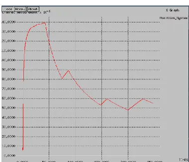
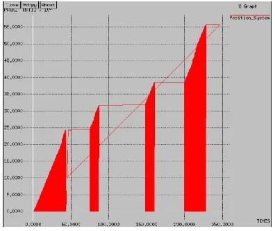
IV. S IMULATION RES ULTS
Fig 1. Packet loss 𝑉s Time
Fig 2.Delay Vs Time
Fig 4. Throughput Vs Time
V. CONCLUS ION AND FUT URE WORK
We recognize resource allocation in the 3GPP LTE-A ce llu lar transmission that concede for MIMO fro m each scheduled user further multi-user scheduling. The same time frequency resource are assigned in the multi user. The NP- hard is a proble m in resource allocation and constant-factor polynomia l t ime appro ximat ion is proposed.
Enhance localization-aided localizab ility (LA L) protocol. certa in locations in the network might be mo re e xpensive to instrument than others because they are less accessible. We might also have several sensor models to choose from, e,g., a h igh cost, high accuracy sensor, and a low cost, low accuracy sensor.
REFERENCES
[1] 3GPP, “T SG-RAN EUT RA, rel.10,” TR 36.213, Dec. 2010.
[2] W. Yu and W. Rhee, “Degrees of freedom in wireless multiuser spatial multiplex systems with multiple antennas,” IEEE T rans. Commun., vol. 54, pp. 1747–1753, Oct. 2006.
[3] N. Bansal, N. Korula, V. Nagarajan, and A. Srinivasan, “On k-column sparse packing programs,” in Proc. 2010 International Conf. Integer Programming Combinatorial Optimization.
[4] W. Yu and R. Liu, “Dual methods for nonconvex spectrum optimization of multicarrier systems,” IEEE Trans. Commun., vol. 54, pp. 1310–1322, July 2006.
[5] N. Prasad, K. Li, and X. Wang, “Fair rate allocation in multiuser OFDMSDMA networks,” IEEE Trans. Signal Process., vol. 57, pp. 2797–2808, July 2009
[6] W. Dai, B. C. Rider, and Y. Liu, “Joint beamforming for multiaccess MIMO systems finite rate feedback,” IEEE Trans. Wirele ss Commun., vol. 8, pp. 2618–2628, May. 2009.
[7] S. N. Donthi and N. B. Mehta, “Joint performance analysis of channel quality indicator feedback schemes and frequency-domain scheduling for LT E,” IEEE Trans. Veh. Technol., Sept. 2011.
[8] M. Andrews and L. Zhang, “Multiserver scheduling with contiguity constraints,” in Proc. 2009 IEEE Infocom.
[9] H. Yang, F. Ren, C. Lin, and J. Zhang, “Frequency-domain packet scheduling for 3GPP LTE uplink,” 2010 IEEE Infocom.
[10] N. Prasad, H. Zhang, M. Jiang, G. Yue, and S. Rangarajan, “Resource allocation in 4G MIMO cellular uplink,” 2011 IEEE Globecom. [11] S. B. Lee, I. Pefkianakis, A. Meyerson, X. Shugong, and L. Songwu, “Proportional fair frequency-domain packet scheduling for 3GPP LTE uplink,” in Proc. 2009 IEEE INFOCOM. [15] N. Prasad, H. Zhang, H.Zhu, an d S. Rangarajan, “Multi-user scheduling in the 3GPP LTE cellular uplink,” 2012 IEEE WiOpt. Extended version to appear IEEE Trans. Mobile Comp.
[12] 3GPP, “T SG-RAN EUTRA, rel.8,” TR 36.101, June 2011.
BIOGRAPHY
Vijaya l akshmi A pursuing Master of Engineering (M E) in the Electronics Depart ment of Electronics and Co mmunicat ion, Kingston Engineering Co llege, Anna University. She received Bachelor of Engineering (BE) degree in 2014 fro m Anna University, Chennai, India.