Division III
INFLUENCE OF FUEL MODELLING ON AIRCRAFT IMPACT -
COMPARISON OF SPH APPROACH AND DISCRETE MODELLING
Alexander Siefert1, Fritz-Otto Henkel2 1
Engineering Director Numerical Analysis, Wölfel Engineering, Germany
2
Senior Expert, Wölfel Engineering, Germany
ABSTRACT
Within the last decade numerical approaches for investigating the impact of passenger aircrafts have been developed steadily and nowadays the integral simulation method is more or less state of the art, see Siefert (2011). A challenge in these simulations is still the modelling of the fuel. The typical approach is to model the fuel via discrete mass elements and merge them to surrounding structural elements in the area of the wings, the wing box and the tail. Using this procedure the fluid character of the fuel, which could e.g. cause a splashing while impact a stiff structure, is not considered. Further the interaction between fuel and the structural setup is not taking into account.
A more sophisticated approach is the application of the smoothed hydrodynamic particle method (SPH), see Gingold (1977) and Monaghan (1992). Thereby the fluid is modelled via small particles which interact via a general contact definition and therefore can represent the behaviour of a fluid. A general disadvantage is the very high computational effort using the SPH method. Accordingly the user has to make a balance between the benefit using the method and the required analysis effort. There have been several publications showing the general capabilities using SPH, see Kirkpatrick (2006), Lee (2014) and Wilt (2011).
The focus of the work here presented was to compare both procedures for the impact of a B747 on a rigid or on a concrete wall with or without an obstacle in front of it. Based on the results general recommendations for the application of SPH will be defined.
INTRODUCTION
The setup of an aircraft can be separated in structural and non-structural parts. Using the finite element method (FEM) typically shell and beam elements are used to model the structural parts. The standard approach for representing non-structural parts as e.g. the fuel or the payload is the application of discrete mass elements merged to surrounding structural elements like shells or alternatively an increase of material density. The disadvantage of this approach is that the additional masses are rigidly attached to the structural elements leading to unrealistic inertia forces. This is especially the case for the fuel as the inertial behaviour of a fluid is totally different to structural elements, what can be easily be shown by the splashing effect of a fluid while impacting a structural surface.
In general one disadvantage using SPH is the very high computational effort. Depending on the model complexity and on the fluid spreading the computational time using SPH could by twice or higher than using the discrete mass element approach. Therefore it is very important to define some general recommendations for using or not using the SPH method.
In the work here presented both procedures have been used first for the impact analysis of B747 on a rigid wall to compute the load time function (LTF). Thereby an enhanced evaluation procedure will be presented introducing a spatial component on top of the LTF. Further the interaction with an obstacle at different positions in front of the wall was analysed. In the second step the impact of B747 on a reinforced concrete will be presented and the computed damage using SPH or discrete masses will be analysed. In the paper both approaches are named discrete and particle.
IMPACT ANALYSIS RIGID WALL
The first step of the work presented was to execute an impact analysis on a rigid wall with a B747 model using discrete mass elements or particles for the fuel to compute the load-time-function.
Model Setup B747
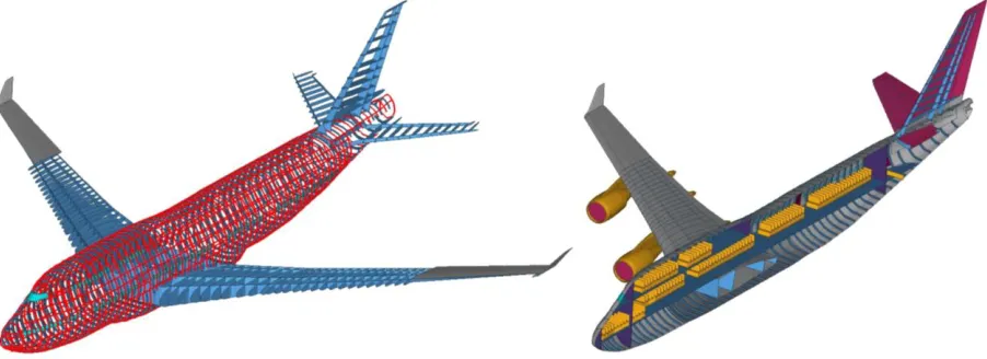
In this analysis a detailed model of the aircraft B747, which was developed in the last years, will be used. In the model setup the following main features influencing the impact load are considered:
Fuselage including ribs and stringers
Wings and tail including stringers and wing box Turbines with fixation at wings
Fuel modelled with SPH approach / discrete mass elements Payload distributed over fuselage and seats
The following figure 1 shows the general setup of the aircraft using shell and beam elements for the structural parts.
In reality different materials as aluminium, titanium, steel, rubber, glass and plastic are used in the structural setup of an aircraft. For all materials nonlinear behaviour is assumed. Taking strain rate dependent effects into account the approach of Johns-Cook is used for all metallic parts. The material is defined following equation 1, Johnson (1983).
0
ˆ
1 ln 1
pl n
pl m
A B C
Equation 1: Constitutive law of Johns-Cook for metal plasticity.
Finally the failure of the material is defined via the Damage Initiation and Damage Evolution options, which are available in ABAQUS (2014). The weight of the B747 is defined in the analysis with 400 t, what represents the Maximum Take Off Weight (MTOW). Thereby the fuel consumption due to the starting of the aircraft and the flight distance is not considered.
Simulation and Analysis of the LTF
The computation of the LTF is carried out by simulating an impact on a rigid wall. Typically the wall is represented by one rigid body enabling a fast evaluation of the LTF via the reaction forces of the reference node, which is fixed in the simulation. The disadvantage of this evaluation procedure is its limited informational value as the complete impact is only described by one integral value. Additional information like the spatial distribution of the load cannot be evaluated.
Therefore the modelling of the rigid wall was enhanced in the carried out study. The wall was separated into 455 rigid bodies, each with the dimension of 2 x 2 m². In the simulation the reference nodes of all 455 elements can be evaluated separately enabling a spatial distribution of the impact load. Especially for the investigation of the fluid effects of the particle approach this represents a benefit compared to the typical procedure.
Figure 2. Deformed state at 250 and 500 ms of discrete (top) and particle approach (bottom)
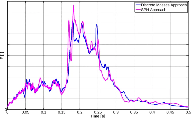
Several differences can be observed between the two computations with respect to the deformation of the aircraft. In general the particle approach shows a greater dispersion of the damaged fuselage and wing parts. The reason is that after the fuel tank gets into contact with the rigid wall a splashing of the fluid inside starts leading to an acceleration of the surrounding structural parts orthogonal to the flight direction. Nevertheless the overall impact on the rigid wall is very similar which can be visualized comparing the LTF of both computations, see figure 3.
0 0.05 0.1 0.15 0.2 0.25 0.3 0.35 0.4 0.45 0.5
0
F
[
-]
Time [s]
Discrete Masses Approach SPH Approach
Figure 3. LTF of impact B747 on rigid wall with 140 m/s
0 10 20 30 40 50 60 20
15
10
5
0
0 1000 2000 3000 4000 5000
0 10 20 30 40 50 60
20
15
10
5
0
0 1000 2000 3000 4000 5000
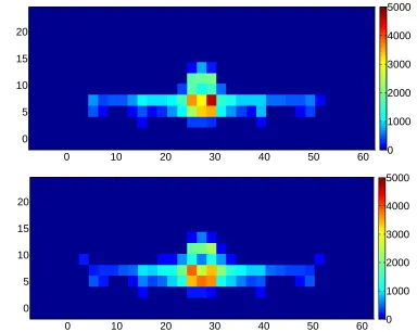
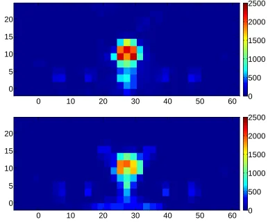
Figure 4. Momentum (kNs) force of each panel for discrete (top) and particle (bottom) simulation
While the maximum force of each panel not really differs between both computations a general effect can be observed on the momentum. There the particle approach shows a greater distribution of the impulse in the area of the fuselage, which was expected looking on the deformed shape of the aircraft at 500 ms. This leads to the conclusion that using SPH reduces the local loading in the area of the fuselage which obviously would also reduce local damage in this area.
Analysis of Interaction with Obstacle
In the second step the interaction with an obstacle in front of the rigid wall is investigated. The obstacle is defined as a rigid triangle with a height of 1.6 m and is positioned in front of the aircraft in the area of the wing box, see figure 5.
Figure 5. Dimension and position of the rigid obstacle in front of the aircraft
In a first analysis the obstacle is positioned directly in front of the rigid wall, i.e. that almost no space is left between the obstacle and the front surface of the final objective. The results of this analysis are very similar to what was presented for the computation of the LTF before. For both approaches, discrete and particle, the computed impact load on the rigid wall, evaluated via the LTF, are very similar, but the particle approach shows a greater distribution of the load in the area of the fuselage.
In the second analysis the obstacle was moved 10 m from the final objective away, to investigate the geometrical effect of the obstacle position on the final impact load. In figure 6 the deformed state of the aircraft at 100 and 400 ms are presented for the both procedures.
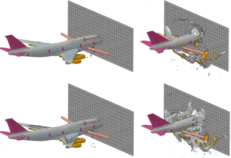
Figure 6. Deformed state at 100 and 400 ms of discrete (top) and particle approach (bottom)
It can be seen up to 150 ms that the lower part of the fuselage is ruptured by the obstacle. The upper part of the fuselage is almost not influenced, i.e. the inertia effects activated via the defined velocity are dominating the impact behaviour. After the obstacle gets into contact with the wings and the wing box, respectively the fuel tanks in this area, also surrounding structural parts are influenced, i.e. ruptured parts are accelerated orthogonal to the flight direction.
0 10 20 30 40 50 60 20
15
10
5
0
0 500 1000 1500 2000 2500
0 10 20 30 40 50 60
20
15
10
5
0
0 500 1000 1500 2000 2500
Figure 7. Momentum (kNs) force of each panel for discrete (top) and particle (bottom) simulation
As expected the representation of the fuel via the particle solution enables the representation of the fluid behaviour and initiates a splashing effect in the area of the fuselage. This can easily be visualized via the momentum of the 2 x 2 m² panels, where the particle approach shows impacted areas outside of the fuselage. A significant reduction of about 25 % can be observed in the area of the fuselage.
Based on the results for the impact on the rigid wall with or without an obstacle in front of it, it can be summarized that using the SPH approach leads in general to a reduction of the local load in the area of the fuselage. Nevertheless it must be mentioned that this plays a more significant role if the aircraft hits an obstacle in front of the final objective and further the influence of the effect increases with the distance between obstacle and objective.
IMPACT ANAYLSIS REINFORCED CONCRETE WALL
Figure 7. Setup reinforced concrete wall
For the wall a nonlinear material behaviour is considered including strain rate dependence and a failure criteria. For the concrete the Damaged Plasticity Model and for the steel the Johnson Cook approach are applied in ABAQUS.
The aircraft is positioned at the centre of the wall. The interaction between all model parts is defined by the general contact algorithm. The simulation represents an impact duration of 500 ms. The computation was carried out on a server with 16 cpus. The computational effort using particles instead of discrete masses was about 30 %.
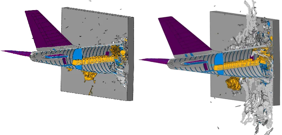
Figure 8. Deformed state at 350 ms of discrete (left) and particle approach (right)
In figure 8 the deformed state of the aircraft and the concrete wall is presented at 350 ms for both calculations. In general the structural behaviour seems similar, but once again the splashing effect of the fluid in the centre tank influences for the particle solution the surrounding parts. The horizontal and vertical moving of this parts is much greater compared to the discrete mass approach.
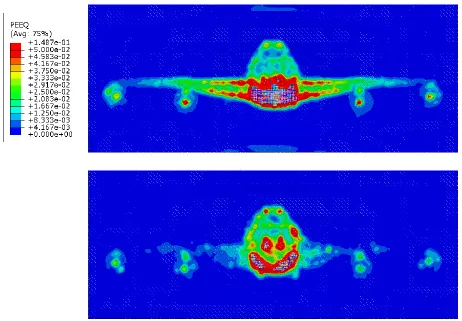
equivalent plastic strain is presented for the impacted frontal surface of the wall at the state of 400 ms. By the contour plot it can be seen that the area with a greater damage of the concrete is much higher for the analysis using discrete elements than for the particle approach. As a consequence of this the number of eroded elements in the impact range of the wing box is also much higher.
Figure 9. Equivalent plastic strain at 400 ms of discrete (top) and particle approach (bottom)
Summarizing the results of the impact analysis on the reinforced concrete wall it can be concluded that using discrete mass elements is more conservative than using a particles instead.
CONCLUSION
An open question in the investigation of the load case aircraft impact is still the modelling of the fuel. Typically it is represented via the increase of the density of structural elements or the discrete mass elements. Both approaches do not consider the fluid behaviour and its influence on the impact. A more sophisticated approach is the application of particles. In the presented study both approaches have been compared to each other for the impact on a rigid wall with and without an obstacle and on a reinforced concrete wall.
Looking on the results of the impact on a reinforced concrete wall it can be summarized that using the particle approach leads to a reduction of the local damage. Accordingly the usage of discrete mass elements is a more conservative procedure.
Finally it has to be mentioned that the computational effort using particles instead of discrete masses is much higher. Accordingly the computational engineer should always make the decision of using or not using this approach depending on the impact scenario and the expected effect of the fluid behaviour. Thereby the existence of obstacle with a specific distance to the final objective is always a supporting argument for the application of the SPH method.
REFERENCES
ABAQUS (Software Package), Version 6.14-1 (2014), ABAQUS Inc., Providence, USA,
www.abaqus.com
Gingold, R. A., Monaghan, J. J.: “Smoothed particle hydrodynamics: theory and application to non-spherical stars”, Monthly notices of the royal astronomical society, 181.3: pp 375-389, 1977
Johnson, G. R., Cook, W. H. (1983): “A constitutive model and data for materials subjected to large strain, high strain rates and high temperature”, Proceedings Int. Symposium Ballistics, pp. 541-547. Kirkpatrick, S.W. et al.: “Modelling Methodologies for Assessment for Aircraft Impact on the World
Trade Centre Towers”, LS-Dyna Users Conference, Detroit, 9 53 – 67, 2006
Kostov, M. et al.: “Non-Structural Mass Modelling in Aircraft Impact Analysis”, SMiRT 23th Conference, Manchester, UK, 2015
Lee, K. et al.: “Advanced Aircraft Analysis of an F-4 Phantom on a Reinforced Concrete Building”, Nuclear Engineering and Design 273, pp. 505-528, 2014
Monaghan, J. J.: “Smoothed Particle Hydrodynamics”, Annual review of astronomy and astrophysics, 30: pp. 543-574, 1992
Siefert, A. et al.: “Nonlinear Analysis of Commercial Aircraft Impact on a Reactor Building - Comparison between integral and decoupled Crash Simulation”, SMiRT 21th Conference, New Delhi, Indi, 2011