Division V
INFLUENCE OF PIPING SUPPORT CONDITIONS ON STRUCTURAL
DYNAMICS INCLUDING POST-INSTALLED ANCHORS
Klaus Kerkhof1, Fabian Dwenger1, Veit Birtel1, Thilo Fröhlich1, and Fritz-Otto Henkel2
1
Materials Testing Institute (MPA), University of Stuttgart, Germany 2
Wölfel Beratende Ingenieure, Höchberg, Germany
ABSTRACT
Nowadays the structural behaviour of a mechanical system can be calculated quite accurately by means of large Finite Element (FE-) Models. But these FE-calculations can only be as reliable as the system model can realistically describe the present support stiffness or its imperfections. Therefore, it is likely that calculated natural frequencies differ considerably from natural frequencies determined experimentally. For systems which show such frequency deviations between calculated and experimentally determined natural frequencies, the predictions of stress analysis in dynamic load cases may be unrealistic. Examples of such frequency deviations are given regarding seismic loading of piping. Overestimations and underestimations of stress analyses may occur depending on whether the natural frequency shifts into or out of the plateau of the applied floor response spectrum.
In nuclear engineering, site-specific seismic loading is of particular importance for design of structures and components located therein. The seismic event leads to loads that can exceed those of normal operation and may be relevant to failure. During seismic events power plants are subjected to horizontal and vertical vibrations. Components such as piping systems are often mounted to massive concrete constructions like floors and shear walls by post-installed anchors. Post-installed fastening constructions with anchor plates and anchors have to transfer the forces resulting from the interactions between structure and component. The coupling of the individual sub-systems (structure, support, and component) leads to dynamic interactions that are significantly influenced by the load bearing behaviour of the fastening elements. Numerical and experimental studies within a current research project regarding these interactions are described in the paper.
INTRODUCTION
For checking the boundary characteristics and stiffness, a comparison of experimental and calculated modal analysis data was carried out and model-updating procedures were performed in some cases.
The first example - which deals with a small diameter piping system with nominal diameter DN25 - represents the case in which the real boundary stiffness is greater than the assumed one in the design calculation. As a consequence, the natural frequency of the real system lies at a higher frequency outside of the floor response spectrum plateau. This leads to overestimations of stress analyses in the design calculation.
The second example shows the influence of a model which is too simplistic. Here, only a resulting vertical stiffness of two parallel struts was modeled. Finally only a detailed model taking into account the position of the two strut-supports leads to a good agreement between calculated and measured natural frequencies. In this case underestimations of stress analyses might occur because the natural frequency could shift into the plateau of a floor response spectrum from lower to higher frequencies.
post-installed anchor – piping” under seismic loading is the subject of current investigations during the research project,Kerkhof et al. (2015), sponsored by the German Federal Ministry of Economics and Energy.
CASE STUDY OF SUPPORT STIFFNESS FOR SMALL DIAMETER PIPING AND ITS INFLUENCE ON STRESS ANALYSIS IN CASE OF SEISMIC LOADING
The investigated piping system with nominal diameter DN25 consists of four supports where the estimation of stiffness was difficult. These boundaries are clamps or welded connections to other stiffer constructions – altogether in the lower part of the system. There are no other supports like springs and struts. The system branches from the bottom upwards via two T-pieces into three branches which are fixed to a vessel. A Stress analysis regarding seismic loading was performed twice with the FE-code Rohr2 by KAH (2010) as well as with Abaqus FEA by Kerkhof (2011). Rohr2 allows providing flexibility factors for the elbows. The Abaqus model consists of ELBOW31 elements for the whole system taking into account cross section ovalization for the elbows as well as for the adjacent straight pipes to consider decreasing ovalization.
Taking into account the same stiffness values for the supports, the first three natural frequencies and corresponding modes of the hot system were calculated with both models in good accordance, table 1. First, supports No. 1 and 2, see figure 1 (a), were assumed as guiding support in y-direction and with a spring stiffness of cwx = 500 N/mm in horizontal and cwz = 500 N/mm in vertical direction, KAH (2010). These values are slightly higher than the values given in Table 5.3 of VDI Guidline 3842 (2004) as “Orientation values for translatory stiffness of supports” with the characteristic “normal”.
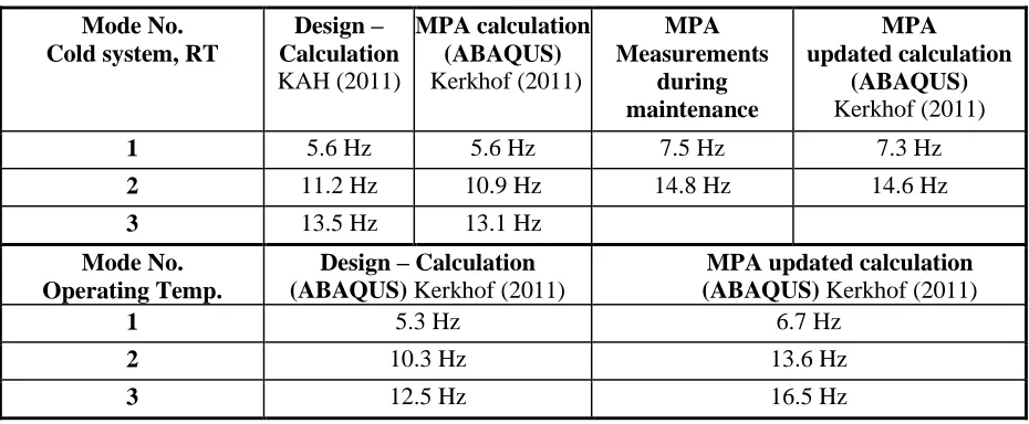
Table 1: Comparison between two different models, between measurement and calculation and between design calculation and updated calculation
Mode No. Cold system, RT
Design – Calculation KAH (2011) MPA calculation (ABAQUS) Kerkhof (2011) MPA Measurements during maintenance MPA updated calculation (ABAQUS) Kerkhof (2011)
1 5.6 Hz 5.6 Hz 7.5 Hz 7.3 Hz
2 11.2 Hz 10.9 Hz 14.8 Hz 14.6 Hz
3 13.5 Hz 13.1 Hz
Mode No. Operating Temp.
Design – Calculation (ABAQUS) Kerkhof (2011)
MPA updated calculation (ABAQUS) Kerkhof (2011)
1 5.3 Hz 6.7 Hz
2 10.3 Hz 13.6 Hz
3 12.5 Hz 16.5 Hz
a) b) c)
Figure 1. a) Piping system and visualization of Mode 1 (5.6 Hz); Comparison of modes, b) mode 2 from design calculation (10.3 Hz); c) Mode 2 (13.6 Hz) of updated calculation model
with fixed support No. 1 and No. 2 circled in red
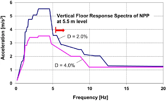
The piping is fixed to a floor at the level of 5.5 m in a Nuclear Power Plant (NPP). The corresponding typical floor response spectrum is shown in figure 2. Seismic loading of the system depends on the shape of the spectrum. If the first eigenfrequency lies in the ascending line onto the plateau resp. descending line, the influence of a potential shift of the first eigenvalue on the numerical results is rather high. In this case, taking the first eigenfrequency from the design calculation (using the Young’s Modulus valid for the hot operating system) with 5.3 Hz instead of the more realistic one from the updated calculation model, which is 6.7 Hz, leads to an overestimation of the load case “earthquake” regarding the v. Mises stress of the highest loaded point at the indicated elbow in figure 3.
Figure 2. Floor response spectrum at level 5.5 m for two damping values
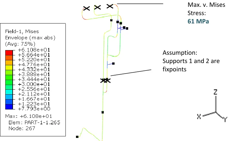
Although the change of level of the plateau for horizontal and vertical response spectra is quite small regarding this frequency shift from 5.3 Hz to 6.7 Hz, the determined max. v. Mises stress (figure 3) decreased 20% from σv = 74 MPa to σv = 61 MPa.
Mode 1
5.3 Hz
Lumped masses of valves and flanges
Supports No. 1+2
Support No. 3
Support No. 4
Position of max. displacement Fixed connections
to a vessel
Figure 3. Load case “dead load” + “vert. Seismic Loading”
CASE STUDY ON INFLUENCES REGARDING THE LEVEL OF DETAIL FOR MODELING PIPING SUPPORTS
During a former research project, Kerkhof et al. (2001), first experiences were gained with operational modal analysis using high sensitive seismic sensors for piping measurements and model-updating. In one case no hanger with a nonlinear load - displacement behavior or energy dissipation as it is typical for constant hangers was present in the investigated piping system. Therefore the vibration measurements yielded a distinct frequency spectrum with a first natural frequency above 2 Hz.
On the other hand the design calculation for the first natural frequency was determined to be 1.43 Hz. Looking into details of the design calculation it turned out that all hangers built with two parallel struts, respectively two parallel spring hangers, were idealized using one vertical stiffness. That means that the design model is less stiff compared to the system as built especially for movements in horizontal directions as it is explained in figure 4. Within Kerkhof et al. (2001) a detailed model was created taking into account the real position of the two struts leading to a good accordance between calculated and experimentally determined natural frequencies of the first mode with a calculated frequency of 2.4 Hz and an experimentally determined natural frequency of 2.5 Hz.
Figure 4. Typical construction of a hanger of the investigated piping system with parallel struts, the deflection figure shows that translational and torsional stiffness is present
Assumption:
Supports 1 and 2 are fixpoints
INTERACTIONS BUILDING - ANCHORS - PIPING DURING DYNAMIC LOADING
When earthquakes occur power plants are subjected to horizontal and vertical vibrations via subsoil. These vibrations are transferred to the structure and to machine components which are fixed to the structure. The system response of this coupled system depends on the one hand on magnitudes, amplitudes and excitation frequencies of the earthquake and on the other hand on the structural behavior of the whole system from soil via the foundation to the building and up to the components. Components such as piping systems are mounted to massive concrete constructions like floors and shear walls. Post-installed fastening constructions with anchor plates and anchors are subjected to earthquake loading via the building construction, figure 5. They have to transfer the forces resulting from the interactions between construction and component. During movement of the anchor, attention should be focused on the load-bearing behavior which can significantly change during opening and closing of cracks in the concrete. Change of stiffness, frequency shifts and contact problems at the anchor plate and the clevis connections of the struts might occur. Aim of a research project Phase 1 and Phase 2 (ongoing), Kerkhof et al. (2015), is to investigate how the load-bearing behavior of such anchors can change during an earthquake due to interactions between concrete slab – fastening – and machine component. Basic knowledge regarding the interaction between fastenings and component should be determined to quantify safety margins. Therefore, in order to realistically model the seismic behavior, it is essential to capture the local failure of the anchorage.
The aim of the project is, to develop a relatively simple numerical model for post-installed anchors connecting the components to reinforced concrete (RC-) structure. The model is developed within the framework of spring modeling approach where the influence of cyclic excitations in terms of tension and shear force cycling as well as cycling of crack intercepting the anchor is modeled through a combination of nonlinear springs. The model should provide to simulate failure mechanisms during interactions between piping and RC structure within a model of the whole structure. In order to generate the database for evaluation of spring characteristics, a series of seismic tests following the recommendations of German guideline for anchorages in nuclear power plants were performed. The testing program included monotonic and cyclic load tests in non-cracked and cracked concrete specimens with different specified crack widths. Additionally, crack cycling tests for two different crack width levels were performed. Two different types of undercut anchors that are qualified for the application in Nuclear Power Plants (NPP) were tested under the program. The tests were carried out with a special setup for crack cycling tests. The chosen types of anchors were Hilti HDA and fischer FZA. Both anchors have shown suitability for use in German NPP by approval procedures. The results regarding these investigations are reported at SMiRT23 in Mahadik et al. (2015), Sharma et al. (2015) and Hofmann et al. (2015).
During movement of the anchor, attention should be focused on the load-bearing behavior which can significantly change during opening and closing of cracks in the concrete.
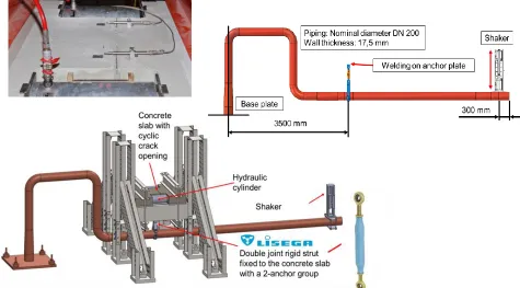
To investigate the structural dynamic interactions including inertia loads of the coupled system “building – fastening with post installed anchor – piping” during earthquake loading, a mock-up, figure 6 - described as follows - was created, where a piping system is mounted to a concrete slab by a double hinged strut and an anchor plate with two undercut anchors. The mechanical part of the model is represented by the piping system, which is fixed on a mounting plate. The pipe is connected via a pipe clamp and a rigid strut to the structural part of the model. The design of the fastening was carried out in that way, that the load case “dead load plus vertical earthquake loading” reaches nearly the design value.
Figure 6. Drawing and components of mock-up, crack cycling performed by means of hydraulic cylinders
Increase of loading should be possible as well, for determining safety margins. Realistic loading scenarios were deviated from a reactor building model. Worst case parameter combinations were determined. In order to generate a seismic time history for the shaker excitation, numerical simulations were carried out as follows: The mock-up piping was theoretically mounted to a floor of the above mentioned nuclear power plant model subjected to high vertical seismic accelerations at a position pointed out in figure 7.
A representative German earthquake load case was simulated by time history analyses. The time histories of the strut load were defined by the following procedure: The
Design Basis Earthquake [DBE (in German: BEB); in US: SSE (Safe Shutdown Earthquake] is the decisive seismic impact for the design of nuclear plants and serves as basis for the definition of the engineering - seismological parameters.
Determination and definition of the Design Basis
Earthquake are done by means of deterministic and probabilistic analyses in accordance with the
specifications of the KTA 2201.1 standard.
The engineering seismological parameters essential for the description of a Design Basis Earthquake (DBE) are ground response spectra with associated peak ground accelerations and the associated strong-motion duration. The ground response spectra are given as free-field response spectra for a site-specific uniform reference horizon. In the framework of this project, a free-field spectrum commonly used for the analysis of nuclear plants serves as basis for the theoretical / numerical analyses of the transfer chain soil-structure-component; the free-field spectrum is loaded with a peak ground acceleration of a0
h
= 2.0 m/s² (horizontal component) and a0
v
= 1,0 m/s² (vertical component). The lower edge of the foundation is applied as reference horizon. The foundation soil corresponds to the structure characteristic for the Rhine Graben (sands and gravels covered by fillings at the surface). As second element of the transfer chain a reactor building with realistic structure, geometry and material data is used as example and implemented in a FE-model with idealization of all significant load bearing elements by means of solid, shell or beam elements respectively and with consideration of the masses via geometry and material weight and density. In addition, a large number of possible connection points of piping systems are specified and defined as possible response points for building response spectra. The numerical simulation of the transfer chain is divided into the following major processing stages:
Generation of acceleration time-histories: The total duration of one earthquake sequence is assessed to be 10 s.
Determination of the associated foundation soil parameters: The decisive soil-mechanical properties are the shear modulus and the density of the soil. The shear modulus increase over the depth.
Eigenvalue analysis with consideration of the soil-structure-interaction Determination of response time-histories and building response spectra.
The results of these analyses, presented in Ries et al. (2015), furnish realistic acceleration time-histories or building response spectra that can be derived from the possible connection points of piping systems in the reactor building and are therefore realistic input values for the large-scale testing at the mock-up. Dimensioning of the piping system for the full-scale test set-up was carried out on the basis of finite element analyses. The numerical analyses revealed that with the selected test set-up the tensile strength with total failure of the fastening construction can be achieved by an anchor plate with two anchors in order to determine design margins. Either a Hilti HDA-T M12 anchor resp. a Fischer FZA M12 anchor meet these demands and were chosen for the mock-up tests. Further details to the design of the mock-up are given in Kerkhof et al. (2015) and to the design calculation in Dwenger et al. (2015). For the tests, a shaker signal was generated which creates a system response of the test set-up with strut load time histories similar to those calculated in situ by means of the nuclear power plant building model, Ries et al. (2015). These signals were scaled to achieve a loading level at the fastening construction close to the decisive design resistances. The test program
for the
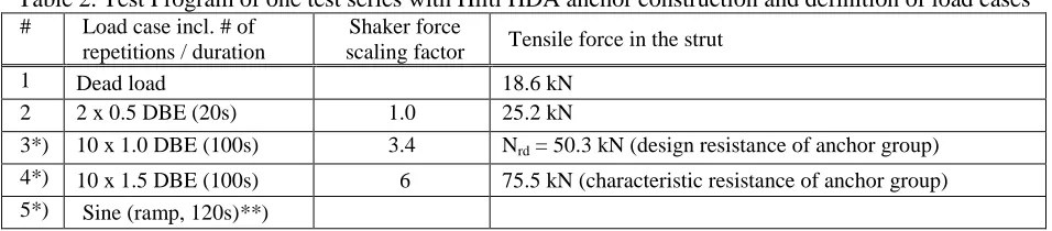
Hilti HDA fastening construction is given in table 2. The design resistance of this fastening construction for tension loading is 50.3 kN. For investigation of load capacities this load was increased, see table 2. An impression of instrumentations gives figure 8.Table 2. Test Program of one test series with Hilti HDA anchor construction and definition of load cases # Load case incl. # of
repetitions / duration
Shaker force
scaling factor Tensile force in the strut
1 Dead load 18.6 kN
2 2 x 0.5 DBE (20s) 1.0 25.2 kN
3*) 10 x 1.0 DBE (100s) 3.4 Nrd = 50.3 kN (design resistance of anchor group) 4*) 10 x 1.5 DBE (100s) 6 75.5 kN (characteristic resistance of anchor group) 5*) Sine (ramp, 120s)**)
Positions 4-7:
Crack width displacement measurements Position 8:
Force measuring ring at anchor 1 (at cracked concrete) Position 9: Force measuring ring at anchor 2
Positions 10-14: Vertical displacement measurements
Ten test series were performed at the mock-up, few depicted results are given in figures 9 to 11: test series 3-1 and 3-2 with Hilti HDA M12 anchors in non-cracked concrete
test series 3-3 and 3-4 with Hilti HDA M12 anchors and crack cycling, crack width 0.4 - 0 mm test series 3-5 and 3-6 with Hilti HDA M12 anchors and crack cycling, crack width 0.8 - 0.5 mm test series 3-7 and 3-8with Hilti HDA M12 anchors and crack cycling, crack width 1.5 - 1.0 mm test series 3-9 and 3-10 with fischer FZA M12 anchors and crack cycling, crack width 1.5 - 1.0 mm
Tensile and compression loads at the double hinged strut were determined by strain gauge measurements. All components built-in have shown suitability for use in German NPP by approval procedures according to German NPP standards. Furthermore, it was postulated that one anchor is installed in cracked concrete.
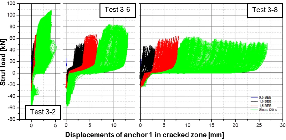
Figure 10. Load-displacement diagram of anchor 1 with Hilti HDA anchors during test 3-2 with non-cracked concrete, during test 3-6 with crack cycling 0.8-0.5 mm and during test 3-8 with crack cycling
1.5-1.0 mm at 0.5 DBE level, 1.0 DBE level, 1.5 DBE level and sine resonant excitation
The crack goes through the borehole so that the undercut is located in the cracked area. Crack cycling was carried out by means of hydraulic cylinders, figure 8. During all tests with Hilti HDA anchors no failure could be observed. During resonant excitation tests for determining load bearing capacities a thread failure occurred at the anchor in the non-cracked concrete. During all tests, gradual pull-out occurred. During sine resonant excitation tests for determining load bearing capacities with fischer FZA anchors, anchor 1 in cracked concrete was pulled out during test 3-10, figure 11. Therefore an inclination of the anchor plate occurred resulting in a plastic deformation of the anchor in non-cracked concrete but without total failure.
Figure 11. Failure of anchor 1, test 3-10
Furthermore verification tests are planned where crack cycling should be realized with earthquake like frequencies during phase II of the project: The piping will be mounted to an anchor plate and a long RC-slab by a strut. The interactions of the vibrating coupled system are going to be investigated.
CONCLUSION
stiffer than assumed. The first natural frequency was higher than calculated by means of the design model and was therefore moving to the right side out of the plateau of the applied floor response spectrum. Another system where this frequency shift would run not conservatively into the plateau is presented as well. Interactions of the coupled system “soil – building – post-installed anchor – piping” at earthquake loading are the subject of current investigations and experiments in a research project, Kerkhof et al. 2015. The main features of the project are described. During all earthquake tests with Hilti HDA anchors no total failure could be observed. During resonant excitation tests for determining load bearing capacities a thread failure occurred at the anchor in the non-cracked concrete. During the earthquake tests with fischer FZA anchors gradual pull-out occurred. During resonant excitation tests for determining load bearing capacities, the anchor in cracked concrete was pulled out totally. An inclination of the anchor plate occurred resulting in a plastic deformation of the anchor in non-cracked concrete without total failure.
ACKNOWLEDGEMENTS
The presented project was funded by the German Federal Ministry of Economic Affairs and Energy (BMWi, project no. 1501450 and project no. 1501478) on basis of a decision by the German Bundestag. The authors like to convey their acknowledgements to LISEGA for discussions and technical support.
REFERENCES
Kerkhof, K., Bauer, Th., Birtel, V., Dwenger, F., Fröhlich, Th., Henkel, F.-O., Hofmann, J., Lotze, D., Mahadik, V. Ries, M. and Sharma, A. (2015). “Interactions of the coupled system "building - post
installed anchor - piping" at earthquake loading” Experimental part, phase I, Final Report, German Reactor Safety Research – Project No. 1501450, and phase II Safety Research –
Project No. 1501478, Germany, ongoing
KAH, Kraftanlagen Heidelberg (2010). „KKP1, Statische und dynamische Berechnung zum Nachweis des Rohrleitungssystems TE16 Z103/104/105 und RY12 Z101 im Dichtungssperrwassersystem für die Zwangsumlaufpumpen“, As-Built-System, Rev. 2, vom 19.04.2010
Kerkhof, K. (2011). Prüfung von Unterlagen zur Erdbebensicherheit des Rohrleitungssystems KKP1 TE16, Materialprüfungsanstalt Universität Stuttgart (MPA Stuttgart), Prüfungsbericht v.15.02.2011 VDI Guidline 3842 (2004).“Vibrations in piping systems”, Verein Deutscher Ingenieure, Düsseldorf Kerkhof, K. et. al. (2001). “Integrity Verification of safety-relevant piping by means of vibration analysis,
Phase II: System investigations to determine stiffness of bearings indirectly, Final Report Reactor Safety Research – project No. 1501062”, Material Testing Institut (MPA Stuttgart), University of Stuttgart, November 2001
Mahadik, V., Sharma, A.,and Hofmann, J. (2015). “Modelling of structure-anchor-component interaction for nuclear safety related structures under seismic loads – Part 1: Generation of experimental database”, Proceedings of SMiRT 23, Manchester, UK
Sharma, A., Mahadik, V.,and Hofmann, J. (2015). “Crack Cycling Tests on Undercut Anchors for Application in Nuclear Safety Related Structures with Different Tension Loading Protocols”,
Proceedings of SMiRT 23, Manchester, UK
J. Hofmann, Mahadik, V., and Sharma, A. (2015). “Modelling of structure-anchor-component interaction for nuclear safety related structures under seismic loads – Part 2: Development of numerical model”,
Proceedings of SMiRT 23, Manchester, UK
Dwenger, F., Kerkhof, K., Birtel, V. and Fröhlich, Th. (2015). “Experiments on seismic performance of piping mounted to a concrete floor by post installed anchors” Proceedings of the ASME 2015
Pressure Vessels & Piping Conference, paper no. 45777, ASME PVP 2015, Boston, MA, USA Ries, M., Bauer, Th., Hahn., T. and Henkel, F.-O. (2015). “Seismic test of pipe system supporting anchors