Real Time GPRS- Fuel Tracking and
Monitoring Entity Using Telematics
Dhivyasri G, Rajeshwari Mariappan
PG Scholar, Dept of ECE, Kumaraguru college of technology, Coimbatore, India
Research Scholar, Dept of ECE, Kumaraguru college of technology, Coimbatore, India
ABSTRACT: Telematics is an eminent technology which merges telecommunications and informatics. This blending
of computers and wireless telecommunications technologies is done ostensibly with the goal of efficiently conveying information over vast networks to handle vehicle information’s. The entire system consists of TeCU Telematics Control Unit, server and webpage application to monitor and to sense ample information’s received from vehicle over the air. Telematics Control Unit (TeCU) has to be designed and developed, which could be used in real time and off time monitoring, tracking and reporting system. TeCU is mounted in the vehicles and it’s implemented with GSM/GPRS for tracking to communicate with backend server. The user can create a webpage application and monitor the vehicle update information’s and mappings with fine precision. Thus, system provides adequate information to fleet operator regarding route/direction taken by driver, stoppages, vehicle location, speed of the vehicle, engine speed, idle mode, AC ON or OFF, vehicles unit information’s, RPM, high acceleration, sudden braking, date, time, etc. All these vehicle information’s from TeCU could be updated to the Server; this is possible through GPRS communication. Thus server dispatch’s all information’s completely to end user webpage. This system could be extensively used in commercial vehicles and in constant equipments. In this paper fuel indicative sensor and TeCU are interfaced, and then fuel status of vehicle is monitored predominantly on the webpage. Then hardware and software implementations will also be done to administrate the system. This core endeavor is to identify fuel theft, tank failure and manage the fuel pilfering along with some additional features. Then a new entity is also proposed in order to monitor the fuel capacity of vehicles during the refills at bunks which would help to ensure the fuel level present in tanks precisely.
KEYWORDS: Tracking, TeCU-Telematic control unit, GSM/GPRS, Server, Webpage
I. INTRODUCTION
Telematics is the blending of computers and wireless telecommunications technologies, efficiently conveying information over vast networks to improve a host of business functions or government-related public services. Telematics is an interdisciplinary field encompassing telecommunications, vehicular technologies, road safety, electrical engineering (sensors, instrumentation, wireless communications, etc.), computer science (multimedia, Internet, etc.).
II. RELATED WORK
ISSN(Online): 2320-9801
ISSN (Print): 2320-9798
I
nternational
J
ournal of
I
nnovative
R
esearch in
C
omputer
and
C
ommunication
E
ngineering
(An ISO 3297: 2007 Certified Organization)
Vol. 3, Issue 3, March 2015
III.PROPOSED SYSTEMS
A. Fuel Tracking System In Webpage
This paper, serves as the purpose of stating the overall functionality and hardware requirement of the fuel level to be interfaced to the telematics. GSM/GPRS module information is forwarded to server and to the user webpage.
Fig.1 General Architecture
B. Direct Fuel Level Monitoring Entity
The main scope of this entity is to monitor the fuel level of any vehicles during the refills at bunks. Thus if any vehicles has to be refilled, already the level of fuel left in the tank could be at any levels. Thus it could be varied from empty (reserved) till full tank case. By using this compact entity user can check the fuel filled at the time of each refills.
Fig. 2 Block of direct fuel level monitoring entity
IV.IMPLEMENTATION OF FUEL TRACKING SYSTEM IN WEBPAGE C.
Power Supply Unit
A power supply is a device that supplies electric energy to and load. The primary function of a supply is to convert one form of electrical energy to another and, as a result, referred to as electric power converters. Some supplies are stand-alone devices, whereas it’s built into larger devices along with their loads. Initially, 12 volt power supply unit are connected to the vehicles fuel level sensor. The power supply unit could be interfaced with fuel level sensor and its relevant level changes in the tank could be measured.
D. Fuel Level Indicative Unit
Fig.3 Circuit diaReed Switch
A Fuel level sensor incorporates a reed switch in a stem. An external float with a magnetic inside passes and actuates the reed switch depending on the liquid level.
A. Reed Switch
It is a small electro mechanical device having two ferromagnetic reed blades sealed in a glass envelope. When a magnetic field is brought near to this, reeds will close creating the switching functions. Observation of fuel level sensor output from a passenger car
TABLE 1 FUEL LEVEL SENSOR OUTPUT
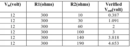
Then the resistance values need to be calibrated between the ranges of (0-5) volt, in order to feed into TeCU controller. Thus calibration is done using potential divider calculation. Initially worst case range has been fixed using trial and error method and then voltage calculations are proceed for all the above assigned resistances of the fuel capacity. Changing the value of the variable resistor R-2 changes the output voltage V-OUT.Calibrated output readings
TABLE 2 CALIBRATED OUTPUT READING
B. Telematic Control Unit
Hardware unit to be installed in the vehicle for should operate for both 12V system, shall continue to operate during cranking voltage of 6.0V complaint with IP67 standard, sleep current should not exceed 4mA. The TeCU functionality should not get affected by any of mechanical or environmental aspect of the vehicle and should not cause any kind of electrical interference to any other electrical/electronic components in the vehicles.
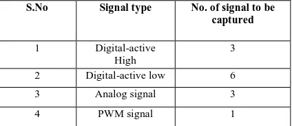
TeCU should have the capability of capturing the following inputs
Vin(volt) R1(ohms) R2(ohms) Verified Vout(volt)
12 300 10 0.387
12 300 30 1.091
12 300 60 2
12 300 100 3
12 300 140 3.818
12 300 190 4.653
Fuel capacity Ohms Ω Tolerance
Empty low (3lit) 10 ±3
Empty high(6lit)-Reserve 30 ±3
¼ position tank(10lit) 60 ±6
½ position tank(20lit) 100 ±6
¾ position tank(30lit) 140 ±8
ISSN(Online): 2320-9801
ISSN (Print): 2320-9798
I
nternational
J
ournal of
I
nnovative
R
esearch in
C
omputer
and
C
ommunication
E
ngineering
(An ISO 3297: 2007 Certified Organization)
Vol. 3, Issue 3, March 2015
TABLE 3 TECUSIGNAL INPUTS
The TeCU circuitry used for tapping active low digital signal should not cause any leakage current to flow in the shared circuitry in the vehicles. All the analog signals are shared only. It should have a quad band GSM modem which can do the functions: Send GPRS data packet to a valid, Receive incoming GPRS data packet URL address, Receive incoming data, should have internal antenna for its GSM functionality.
The TeCU should be equipped with LED to show status of the GSM signal. Also there should be another LED which shows status of the TeCU. When the vehicle is in ignition ON condition, the TeCU should send data packet on the server periodically which should contain the location information of the vehicle at the moment.
This data packet will be termed as tracking data here onwards. Periodicity for tracking the data is mentioned in the table. These parameters are configurable Parameter and configured over the air by sending GPRS data packet or SMS from server to TeCU. The TeCU should detect the alert conditions occurring in the vehicle is given below The TeCU should send data packet to the server whenever it detects an alert, informing the same. These data packet will be termed as alert data packets will be termed as alert data packet here onwards. These parameters to be considered for detecting the alerts should be configurable parameter which can be configured over the air by sending GPRS data packet from the server to TeCU.
In case of no GSM/GPRS signal availability the TeCU should store the periodic tracking data in a separate memory as a stack. This memory is termed as Backlog memory. The Backlog memory should be sized in such a way that it can store 20hrs of tracking data. During the condition mentioned, if an alert is also occurring in the vehicle, then the corresponding alert data packet also has to be stored in the backlog memory with the tracking data. All data packets stored in the backlog memory is termed as backlog data. Whenever the TeCU detects the availability of GSM/GPRS signal after the occurrence of the backlog conditions, the TeCU should send the backlog data in FIFO manner. At the same time TeCU should store the live tracking data in the backlog memory. Three particular live alerts will have more priority when the TeCU is engaged in sending Backlog data, TeCU will stop sending it and will send these alert data packets to the server, and then it will resume sending of backlog data. While the TeCU is engaged in the emptying of backlog memory by sending the backlog data, if an alert occur other than the 3 alerts, it will also be stored in the backlog memory with the live tracking data. The periodicity of sending the backlog data should be less than that of sending live tracking data packet. This time period will be configurable parameter which can be configured over the air by sending GPRS data packet from, the server to TeCU. Even if the vehicle is in ignition OFF state, the TeCU should send backlog data to server if there is any data present in backlog memory.
Once the TeCU empties the backlog memory it will continue to send the live tracking and alert data packets to the server. In any circumstances, if the backlog memory gets fully filled, then the TeCU should delete the oldest data packets in the backlog memory if it has to store new live data packets, once the backlog memory is full, then the backlog has to be cleared in first in first out manner (FIFO) and it should be done only if a new data packet is created to be stored. The TeCU has to send data packet containing the location and time details of its current position for every particular period of time when the vehicle is in ignition OFF state. This data packet will be known as beacon signal data. This time period value should also be a configurable parameter which can be configured over the air by sending GPRS data packet or SMS from server to TeCU.
S.No Signal type No. of signal to be captured
1 Digital-active
High
3
2 Digital-active low 6
3 Analog signal 3
Fig.4 Block of TeCU
C. GSM/GPRS
GSM/GPRS module used to communicate between a computer and a GSM-GPRS system. Global System for Mobile communication (GSM) is an architecture used for mobile communication in most of the countries. Global Packet Radio Service (GPRS) is an extension of GSM that enables higher data transmission rate. GSM/GPRS module consists of a modem assembled together with power supply circuit and communication interfaces (like RS-232, USB, etc) for computer. A GSM/GPRS MODEM can perform the following operations:
1. Receive, send or delete SMS messages in a SIM. 2. Read, add, search entries of the SIM.
I Web Application
Database and application server could be used to receive data from the TeCU and to provide web hosting. Data from the vehicle is through SMS or GPRS; it’s collected in database server which is having static IP. In web application server domain name is kept and accessed with webpage login. In a network environment the following types of servers are used.
The web application represents the complete output of the system. In this system two applications are developed that are linked to each other. First one is used to get the initial position of the vehicle with its fuel level along with some added features and as system will receive the different co-ordinates (longitude and latitude) switching to the next one will be done to get the signal strength. Then fuel level could be observer graphically from the webpage. The application will run on WAMP server and will run only if the internet is in use. WAMP server homepage is shown in diagram.
Fig. 5 Wamp server homepage
ISSN(Online): 2320-9801
ISSN (Print): 2320-9798
I
nternational
J
ournal of
I
nnovative
R
esearch in
C
omputer
and
C
ommunication
E
ngineering
(An ISO 3297: 2007 Certified Organization)
Vol. 3, Issue 3, March 2015
server-side scripting using Active Server Pages (ASP), PHP, or other scripting languages. This means that the behavior of the web server can be in separate files, while it remains unchanged the actual server software.
V. SIMULATION RESULT
Proteus design suite 8 professional software is used to verify the simulation result. The fuel level indicative sensor is interfaced to the pretended TeCU controller and its output results are verified. Thus (0-5) V is given to the ADC 0808- analog to digital controller and then it is connected to the ATMEGA16 controller (instead of original TeCU controller) along with some basic connections. Thus its resultant outputs are being verified.
Level of the tank could be ensured from few led glow. Thus figures listed mainly describes that the variation in fuel capacity is interfaced with the controller
. J. Webpage Output Description
The data from TeCU are forwarded to server through GPRS. Then from server entire information about the vehicle is given to webpage. The webpage is designed in such a way that it could display the information of vehicle along with fuel consumption which is expressed graphically. In this project five devices information are stored in the database server, then application server is designed to observe the vehicle information. Thus graphical user interface utilized is PHP 5.4.3. The graph is plotted between fuel level (liters) verses Mileage (Km), Stating that whenever the fuel consumption tend to be high without a large variation in mileage it’s considered as fuel theft. If the fuel drops levels are continuously high even after the refills it’s identified as fuel tank damage. In graph,
The rise in fuel value describes the refills
The drop in fuel value is identified as fuel theft
The large amount of drop in fuel drop is considered as fuel tank failure
Fig. 10 Output for Device 126001
VIMPLEMENTATION OF DIRECTFUELLEVEL MONITORING ENTITY
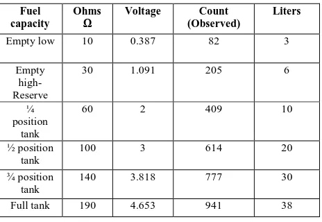
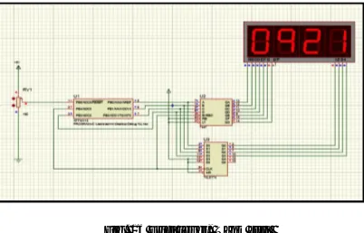
Initially the fuel in tank could be at any level, the fuel level indicative sensor is kept inside the fuel tank of any vehicles like 2 wheeler, 3 wheeler, 4wheeler, commercial vehicles, and heavy vehicles. The observed reading from fuel indicative sensor is given to At Tiny 15 controller. The controller is interfaced with 7447 BCD to seven segment decoder drives and to 74LS174 positive edge triggered flip flops with clear. Then it’s connected to seven segment display to read the value of count. Determining the count value and then with that of interpolation table relevant fuel level present in vehicles fuel tank could be measured. The calibration table to monitor the fuel level directly,
TABLE 4 DIRECT FUEL LEVEL MONITORING
VI.SIMULATION RESULTS
Simulation is the imitation of the operation of a real-world process or system over time. A computer simulation is an attempt to model a real-life or hypothetical situation on a computer so that it can be studied to see how the system works. By changing variables in the simulation, predictions may be made about the behaviour of the system. In this we have designed a system which is used to fetch the fuel capacity of the vehicle and displays its current level especially to check its exact presences before and after the refills in the bunks. Thus output are traced as count values, from this count value by using interpolation table we can determine the fuel capacity in digit values using seven segment displays or LCD monitors. The following figures describes, whenever there is changes in fuel level indicative sensor value of the count is also changed considerably.
Fuel capacity
Ohms
Ω
Voltage Count (Observed)
Liters
Empty low 10 0.387 82 3
Empty high-Reserve
30 1.091 205 6
¼ position
tank
60 2 409 10
½ position tank
100 3 614 20
¾ position tank
140 3.818 777 30
ISSN(Online): 2320-9801
ISSN (Print): 2320-9798
I
nternational
J
ournal of
I
nnovative
R
esearch in
C
omputer
and
C
ommunication
E
ngineering
(An ISO 3297: 2007 Certified Organization)
Vol. 3, Issue 3, March 2015
Fig. 11 Fuel level (empty)
When the observer count value is 0001 the fuel level in the tank is completely empty. It’s justified that the fuel capacity in tank is below 3 liters.
Fig. 12 Fuel level (Reserved)
When the observer count value is 0204 the fuel level in the tank is at reserved level. It’s justified that the fuel capacity in tank is around 6 liters.
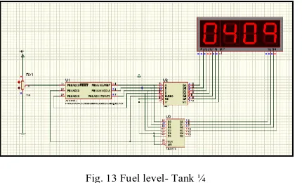
Fig. 13 Fuel level- Tank ¼
Fig. 14 Fuel level- Tank ½
When the observer count value is 0619 the fuel level in the tank is at ½ th level. It’s justified from the table 3.7 that the fuel capacity in tank is around 20 liters.
Fig. 15 Fuel level- Tank ¾
When the observer count value is 0716 the fuel level in the tank is at ¾ th level. It’s justified that the fuel capacity in tank is around 30 liters.
Fig. 16 Fuel level- Tank full
ISSN(Online): 2320-9801
ISSN (Print): 2320-9798
I
nternational
J
ournal of
I
nnovative
R
esearch in
C
omputer
and
C
ommunication
E
ngineering
(An ISO 3297: 2007 Certified Organization)
Vol. 3, Issue 3, March 2015
VII. CONCLUSION AND FUTURE ENHANCEMENT
In this paper, fuel sensors input has been fed into controller and its output response is analysed. This process is done by using Proteus design suite 8 professional software. Thus results is observed that, whenever the resistance value is altered in the reed switch of the fuel level indicative sensor which is kept inside the fuel tank of the vehicle, its relevant voltage is indicated through calibration, accordingly output varies in the TeCU. The data from TeCU is forwarded to server using GSM/GPRS. Then webpage is developed to monitor the fuel level of various devices and analyse if any fuel theft and failure in tanks instantly.
In direct fuel level monitoring entity case users themselves can ensure fuel capacity of their vehicles which helps to observe the fuel level especially before and after refills at bunks.
The current output information about fuel theft and tank failure is obtained from webpage. In future direct fuel monitoring entity could also be included into TeCU, so that both the application could be achieved using a single entity and its relevant outputs can be verified on webpage.
REFERENCES
[1]Pankaj Verma, J.S Bhatia “Design and Development of GPS-GSM based Tracking System with Google map based Monitoring”, International
Journal of Computer Science, Engineering and Applications (IJCSEA) Vol.3, No.3, June 2013
[2]El-Medany, W. Al-Omary, A. Al-Hakim, R. Al-Irhayim, S. Nusaif,M. “A Cost Effective Real-Time Tracking System Prototype Using Integrated GPS/GPRS Module,” Wireless and Mobile Communications (ICWMC), 2010 6th International Conference on,vol.,no.,pp.521,525,20-25 Sept.2010 [3]Tae-Hwan Kim, Cheong-Ghil Kim “Internet-Based Human-Vehicle Interface for Ubiquitous Telematics”, Information Science and Applications
(ICISA), 2013 International Conference on, vol.,no.,pp.1-4,24-26 June 2013
[4]Hu Jian-ming; Li Jie; Li Guang-Hui, “Automobile Anti-theft System Based on GSM and GPS Module,” Intelligent Networks and Intelligent
Systems (ICINIS), 2012 Fifth International Conference on, vol., no., pp.199, 201, 1-3 Nov. 2012
[5]Fleischer, P.B.; Nelson, A.Y.; Sowah, R.A.; Bremang, A., “Design and development of GPS/GSM based vehicle tracking and alert system for commercial inter-city buses,” Adaptive Science & Technology (ICAST), 2012 IEEE 4th International Conference on, vol., no., pp.1, 6, 25-27 Oct. 2012
[6]Nasir M.A.M., Mansor, W (2011) describes “GSM based motorcycle security system”, Control and System Graduate Research Colloquium
(ICSGRC), 2011 IEEE vol., no., pp.129-134, 27-28 June 2011
[7]Le-Tien, T.; Vu Phung-The, "Routing and Tracking System for Mobile Vehicles in Large Area," Electronic Design, Test and Application, 2010.
DELTA'10. Fifth IEEE International Symposium on, vol., no., pp.297, 300, 13-15 Jan. 2010
[8]El-Medany,W.;Al-Omary,A.;Al-Hakim,R.;Al-Irhayim,S.;Nusaif,M., “A Cost Effective Real-Time Tracking System Prototype Using Integrated GPS/GPRS Module,” Wireless and Mobile Communications (ICWMC), 2010 6th International Conference on,vol.,no.,pp.521,525,20-25 Sept.2010 [9]Suqun Cao (2009) describes “GSM Modem-Based Mobile Auxiliary Learning System”, Computational Intelligence and Software Engineering,
CISE 2009 International Conference on, vol. 1, no. 1- 4, and 11-13 December 2009