Design and Analysis of Die and Punch on
Thinning Sheet in Deep Drawing Process
U. Haribabu 1, E.Sarath2
Professor, Dept. of Mechanical Engineering, QIS College of Engineering and Technology, Andhra Pradesh, India1
Student, Dept. of Mechanical Engineering, QIS College of Engineering and Technology, Andhra Pradesh, India 2
ABSTRACT: Deep drawing is a sheet metal forming process in which a sheet metal blank is radially drawn into a forming die by the mechanical action of a punch. . The process is considered "deep" drawing when the depth of the drawn part exceeds its diameter. The model is designed in CREO software. Analysis is done in ANSYS software for different materials in this work the stress have been calculated theoretically as well as Ansys and both results are compared. Modal analysis is done for cup to determine the deformation and frequency for different materials by changing the geometry thicknesses. Random vibration analysis is done for die to determine the directional deformation, shear stress and shear strain for different materials by changing the geometry thickness. Transient analysis is done for die to determine the deformation, stress and strain for different materials by changing the geometry thickness with respect to time. From the static analysis of die and punch AL5083 material having minimum stress value compared to AL7475 and stainless steel. So it can be concluded the geometry thickness is 0.9 mm and material is AL 5083 is best for die and punch.
I. INTRODUCTION
Deep drawing is a sheet metal forming process in which a sheet metal blank is radially drawn into a forming die by the mechanical action of a punch. It is thus a shape transformation process with material retention. The process is considered "deep" drawing when the depth of the drawn part exceeds its diameter. This is achieved by redrawing the part through a series of dies. The flange region (sheet metal in the die shoulder area) experiences a radial drawing stress and a tangential compressive stress due to the material retention property. These compressive stresses (hoop stresses) result in flange wrinkles (wrinkles of the first order). Wrinkles can be prevented by using a blank holder, the function of which is to facilitate controlled material flow into the die radius
FIG1: A Typical Deep Drawing Operation
In the drawn part wall, which is in contact with the punch, the hoop strain is zero whereby the plane strain condition is reached. In reality, mostly the strain condition is only approximately plane. Due to tensile forces acting in the part wall, wall thinning is prominent and results in an uneven part wall thickness, such that the part wall thickness is lowest at the point where the part wall loses contact with the punch, i.e., at the punch radius.
II. LITERATURE REVIEW
Jay N.Mistri, K.D.Kothari,Gaurav, Kumar Sharma all[1], are discussed about Deep drawing is part of forming process in which sheet metal drawn into die cavity by action of a punch. So, due to action of punch desired shape can be achieved. For reduce various defects in deep drawing process it is essential to control or vary physical and geometric parameters of deep drawing process. Sheet-metal drawing is a more complex operation than cutting or bending, and more things can go wrong. Nowadays composite material is extensively used in manufacturing industries due to its better strength.
KrupalT.Shah,SandipChaudhary,DarshanK.Bhatt[2], are discussed about Deep drawing process is a sheet metal forming process where a punch is utilized to force a flat sheet metal to flow into the gap between the punch and die surfaces. As a result, the sheet metal or blank will deformed into desired shape like cylindrical, conic, or boxed shaped part and also complex parts.
Chandra Pal Singh, GeetaAgnihotri [3], are discussed about Deep drawing process has been an important manufacturing process to produce automotive parts of good strength and light weight. There are many process parameters and other factors that affect product quality produced by deep drawing.Deep-drawing operations are performed to produce a light weight, high strength, low density, and corrosion resistible product. These requirements will increase tendency of wrinkling and other failure defects in the product.
P.VenkateshwarReddy,PerumallaJanakiRamulu,G.SandhyaMadhuri,DasariGovardhan and PVS Ram Prasad[4], are discussed about Deep drawing process is a significant metal forming process used in the sheet metal forming operations. Deep drawing process has different effectible process parameters from which an optimum level of parameters can be identified so that an efficient final product with required mechanical properties will be obtained. Punch forces and dome heights are evaluated for all the conditions.
i. Methodology
. Static analysis is done for die and punch to determine the deformation.
Modal analysis is done for die to determine the deformation and frequency for different materials by changing the geometry thicknesses.
Random vibration analysis is done for die to determine the directional deformation.
Transient analysis is done for die to determine the deformation
III. MODELING AND STATIC ANALYSIS OF DIE AND PUNCH
to use the software. This can save businesses by eliminating the need to hire new employees. Their training program is available online and in person, but materials are available to access anytime. A unique feature is that the software is available in 10 languages. PTC knows they have people from all over the world using their software, so they offer it in multiple languages so nearly anyone who wants to use it is able to do so
FIG1.1: 2D Sketch of DieFIG1.2:2D Sketch of Punch
FIG1.3: 3D Model of Die FIG1.4:3D Model of Punch
1.1THEORETICAL CALCULATIONS TO FIND THE STRESS OF DIE
F = (
√ ) × × × × ………... (Eq 3.1)
Where,
t = thickness (mm)
UTS = Ultimate tensile strength (MPa) Do = Die diameter (mm) = 26 mm Blank diameter (D) = D = √d2− 4dh
D = √252- 4(25) (25.0484) D = 24.4930mm
Punch diameter = 25 mm
Blank thickness = 0.5, 0.7, 0.9 mm
Parameters obtained from Sandeeppatil [29]
= F/A ---- (Eq3.2) A= 333.923 mm2
Where,
= stress (N/mm2) P = maximum load (N) A = Area (mm2)
CASE 1- MATERIAL - STAINLESS STEEL
At t = 0.5 mm, Do = 26 mm
=
√ × × 513.61 × 26 × 0.5/333.923
= 62.5 MPa
At t = 0.7 mm, Do = 26 mm
=
√ × × 513.61 × 26 × 0.7/333.923
= 54.4 MPa
At t = 0.9 mm, Do = 26 mm
=
√ × × 513.61 × 26 × 0.9/333.923
= 40.5 MPa
CASE 2- MATERIAL - AL 5083
At t = 0.5 mm, Do = 26 mm
=
√ × × 228 × 26 × 0.5/333.923
= 46 MPa
At t = 0.7 mm, Do = 26 mm
=
√ × × 228 × 26 × 0.7/333.923
= 45.07 MPa
=
√ × × 228 × 26 × 0.9/333.923
= 32.199 MPa
CASE 3 – MATERIAL - AL 7475
At t =0 .5 mm, Do = 26 mm
=
√ × × 345 × 26 × 0.5/333.923
= 63.2 MPa
At t = 0.7 mm, Do = 26 mm
=
√ × × 228 × 26 × 0.7/333.923
= 62 MPa
At t = 0.9 mm, Do = 26 mm
=
√ × × 228 × 26 × 0.9/333.923
= 48.7MPa
Material Properties of Stainless Steel, AL5083, and AL7475
TABLE1.1:Material Properties of Stainless Steel, AL5083, and AL7475
2. STATIC ANALYSIS OF DIE
Static structural analysis for deformation and stress are shown in Figures respectively.
According to the contours plot, the maximum stress at inside of the die because of force acting on the area due to punch applied and the minimum stress at upside, According to the contours plot, the maximum stress at inside of the cup because of force acting on the area due to punch applied and the minimum stress at down side and around the die because of fixed the die.
Materials Modulus Elasticity
Density Tensile Yield Strength
Ultimate Tensile Strength
Poisson's Ratio
Stainless Steel
77 - 310 GPa
0.19 -9.01g/cc
25 – 2500 MPa
34.5 - 3100 MPa
0.22 - 0.346
AL 5083 71 GPa 2.66 g/cc
228 MPa 317 MPa 0.22 - 0.33
FIG2.1: Deformation Contours of D FIG2.2: Stress Contours of Die
2.1. THEORETICAL CALCULATIONS TO FIND THE STRESS OF PUNCH
F= (
√ ) × × × ×
= F/A, A=333.923 mm2 Stainless Steel
At t = 0.5 mm, Dp =25 mm =
√ × × 513.61 × 25 × 0.5/333.923
= 59.74 MPa
At t = 0.7 mm, Dp = 25 mm =
√ × × 513.61 × 25 × 0.7/333.923
= 48.6 MPa
At t = 0.9 mm, DP = 25 mm =
√ × × 513.61 × 25 × 0.9/333.923
= 42.54 MPa AL 5083
At t = 0.5 mm, Dp = 25 mm =
√ × × 228 × 25 × 0.5/333.923
At t = 0.7 mm, Dp = 25 mm =
√ × × 228 × 25 × 0.7/333.923
= 42.4 MPa
At t = 0.9 mm, Dp = 25 mm =
√ × × 228 × 25 × 0.9/333.923
= 41.11 MPa AL 7475
At t = 0.5 mm, Dp = 25 mm =
√ × × 345 × 25 × 0.5/333.923
= 55.23 MPa
At t = 0.7 mm, Dp = 25 mm =
√ × × 228 × 25 × 0.7/333.923
= 52.5 MPa
At t = 0.9 mm, Dp = 25 mm
=
√ × × 228 × 25 × 0.9/333.923
= 46.84 MPa
3. STATIC ANALYSIS OF PUNCH
Static structural analysis of punch for deformation and stress are shown in Figures respectively.
IV. MODAL ANALYSIS OF DIE
The goal of modal analysis in structural mechanics is to determine the natural mode shapes and frequencies of an object or structure during free vibration. It is common to use the finite element method (FEM) to perform this analysis because, like other calculations using the FEM, the object being analyzed can have arbitrary shape and the results of the calculations are acceptable. The types of equations which arise from modal analysis are those seen in Eigen systems
Fig4.1.Total Deformation contours
TABLE4.1 Modal analysis results of Die
Geometry (thickness)
mm
Material Mode shapes Deformation(mm) Frequency (Hz)
0.5
Stainless steel 1 984.7 27046 2 959.21 27165 3 1019.4 28682 AL 7475 1 1649.1 27522 2 1609 29463 3 1692.4 29113 AL 5083 1 1077.5 16819 2 1050.1 16893 3 1101.1 17767
0.7
3 1315 31061 AL 5083 1 838.27 18778 2 881.18 18809 3 851.19 18985
0.9
Stainless steel 1 732.96 38113 2 763.52 38341 3 681.83 39293 AL 7475 1 1243.5 39798 2 1282.4 39201 3 1149.4 39594 AL 5083 1 818.6 23717 2 841.18 23853 3 756.53 24531
V. RANDOM VIBRATIONAL ANALYSIS OF DIE
The Random Vibration analysis uses the results from a modal analysis, specify which design scenario in the current model has the modal results with the Use modal results from Design Scenario field. The Model Units of the random vibration analysis must be
Identical to the Model Units of the modal results
FIG5.1.Shear Stress contour
Here,Table.shownShearstressofAL5083,AL7475 and stainless steel, it can be seen that the minimum shear stress 1.5e5N/mm2 for AL5083 and corresponding shear stress in AL7475 and Stainless steel are 2.94e5 N/mm2, 2,5.405e5
N/mm2.
The Shear stress value occurred minimum for the material AL 5083 at 0.9 mm thickness
5.1. THEORETICAL CALCULATIONS FOR SHEAR STRESS
=4 /(ℎ − ), --- (Eq 5.1) u = Negligible
Stainless Steel --- = 0.3
At t = 0.5 mm, h = 25.0484 mm
=4 × 0.3/(25.0484−0.5)
= 49.8 N/m2
At t = 0.7 mm, h = 25.0484 mm
=4 × 0.3/(25.0484−0.7)
= 49.6 N/m2
At t = 0.9 mm, h = 25.0484 mm
=4 × 0.3/(25.0484−0.9)
= 48.8 N/m2 AL 5083 --- = 0.129
At t = 0.5 mm, h = 25.0484 mm
=4 × 0.129/(25.0484−0.5)
= 21.3 N/m2
At t = 0.7 mm, h = 25.0484 mm
=4 × 0.129/(25.0484−0.7)
= 21.1 N/m2
At t = 0.9 mm, h = 25.0484 mm
=4 × 0.129/(25.0484−0.9)
= 21 N/m2
AL 7475 --- = 0.257
At t = 0.5 mm, h=25.0484 mm
=4 × 0.257/(25.0484−0.5)
At t = 0.7 mm, h=25.0484 mm
=4 × 0.257/(25.0484−0.7)
= 42 N/m2
At t = 0.9 mm, h = 25.0484 mm
=4 × 0.257/(25.0484−0.9)
= 41.8 N/m2
TABLE5.2.Comparison of Theoretical and TABLE5.1.Random Vibration Analysis Results Analytical Shear Stress Value
Materials Thickness (mm) Analytical shear stress (MPa) Theoretical shear stress (MPa) Stainless steel
0.5 5.405×e5 4.9800×e5 0.7 2.945×e5 4.9600×e5 0.9 1.5×e5 4.8800×e5 AL 5083 0.5 6.04×e5 2.1300×e5 0.7 4.28×e5 2.1100×e5 0.9 1.651×e5 2.1000×e5 AL 7475 0.5 9.77×e5 4.2340×e5 0.7 4.72×e5 4.2200×e5 0.9 2.642×e5 4.1800×e5
Geom etry (thick ness) (mm) Mate rial Directi onal Deform ation (mm) Shear Stress (N/mm 2 ) Shear Strain 0.5 Stain less steel
128.1 5.405e5 7.3382
AL 7475
191.79 2.945e5 11.046
AL 5083
116.86 2.642e5 6.7842
0.7
Stain less steel
129.69 6.04e5 8.2066
AL 7475
249.98 4.28e5 15.899
AL 5083
113.21 1.651e5 7.1378
0.9
Stain less steel
2111.8 9.77e5 132.73
AL 7475
2831.2 4.72e5 177.8
AL 5083
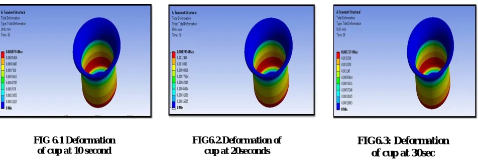
VI. TRANSIENT ANALYSIS OF DIE
A transient dynamic analysis is used to determine the response of a structure subjected to a time-dependent loading considering inertia and damping effects. It is often referred to as a time-history analysis. The full method in ANSYS uses the full system matrices to calculate the transient response at each solution point. The model-superposition method scales the mode shapes and sums them to capture the dynamic response.
Below Figure from shows the maximum stress evaluated in leaf spring at 10, 20 and 30 sec for a given load.
FIG 6.1 Deformation of cup at 10 second
FIG6.2.Deformation of cup at 20seconds
FIG6.3: Deformation of cup at 30sec
FIG6.4: Maximum stress of die at 10 seconds.
FIG6.5: Maximum stress of die at 20 seconds
TABLE6.1: Transient Analysis of Stainless Steel
TABLE6.2: Transient Analysis of AL 7475 Geometry
(thickness)
mm
Time (sec) Deformation
(mm)
Stress
(N/mm2)
Strain
0.5
10 0.00310 25.2051 3.902e-04
20 0.0051328 31.5041 4.5056e-04
30 0.004521 39.0025 5.562e-04
0.7
10 1.63e-03 21.2023 2.8700e-04
20 2.216e-03 27.403 3.5332e-04
30 2.82e-03 31.011 3.9053e-04
0.9
10 2.0107e-03 17.236 2.830e-04
20 1.904e-03 19.330 3.0310e-04
30 2.130e-03 22.3014 3.0338e-04
Geometry
(thickness)
Mm
Time (sec) Deformation
(mm)
Stress
(N/mm2)
Strain
0.5
10 0.0024670 21.302 3.53e-04
20 0.0030458 27.9653 4.1072e-04
30 0.003760 35.064 5.0015e-04
0.7
10 1.48e-03 18.1672 2.6710e-04
20 1.906e-03 22.673 3.03512e-04
30 2.64e-03 27.601 3.7532e-04
0.9
10 1.1205e-03 14.310 2.552e-04
TABLE6.3: Transient Analysis of AL 5083
Geometry (thickness)
mm
Time (sec) Deformation (mm)
Stress (N/mm2)
Strain
0.5
10 0.0021597 19.973 2.94e-004 20 0.0028076 25.965 3.8274e-04 30 0.003454 31.957 4.7115e-04
0.7
10 1.44e-03 15.287 2.1808e-04 20 1.876e-03 19.874 2.8352e-04 30 2.30e-03 24.461 3.4896e-04
0.9
10 1.0734e-03 11.239 1.649e-04 20 1.39e-03 14.611 2.1439e-04 30 1.7174e-03 17.983 2.6357e-04
According to plot the accrues in stainless steel material of 0.9 mm, minimum at 0.9 mm Material AL-5083, Here Material thickness decreases, Shear Stress Will increases as shown in Fig
GRAF6.1: Time Vs Stress 0
5 10 15 20 25 30 35
10 sec 20 sec 30 sec
st
re
ss
(N
/m
m
2)
time
0.5mm
0.7mm
VII. CONCLUSIONS
From the static analysis of die & Punch it is seen that the stress values are increases by increasing the load and decreases with increasing the thickness and deformation values are increases by decreasing the loads at geometry thickness 0.9 mm for AL 5083 material when compared to stainless steel and AL7475.
From the static analysis of cup AL5083 material having minimum stress value compared to AL7475 and stainless steel
The static analysis of punch the stress values are increases by increasing load and deformation values are increases by decreasing the loads at geometry thickness 0.9 mm for AL 5083 material when compared to stainless steel and AL7475.
From the static analysis punch AL5083 material having minimum stress value compared to AL7475 and stainless steel.
The stress values are calculated using analytically as well as using theoretically for die and punch.
The modal analysis of the die deformation values are increases by the loads. The deformation also increases mode shapes of the die. The maximum deformation of geometry thickness 0.5 mm for AL 7475.
The random vibration analysis the shear stress value are increases by increasing the geometry thickness at 0.9 mm in AL5083.
The shear stress values are calculated using analytically as well as theoretically for die.
The transient analysis of die the stress values are increases by increasing load and deformation values are increases by decreasing the time at geometry thickness 0.9 mm for AL 5083 material when compared to stainless steel and AL 7475.
So it can be concluded the geometry thickness is 0.9 mm and material is AL 5083 is best for die and punch.
REFERENCES
[1]Jay N.Mistri, K.D.Kothari,Gaurav, Kumar Sharma,Experimental and Simulation study of Deep drawing process-A review Journal of Advance Engineering and Research Development,Volume1,June,2014
[2] KrupalT.Shah,SandipChaudhary,DarshanK.Bhatt,Analysis of the Effect of process parameters in Deep drawing Journal of Advance Engineering and Research Development,Volume1,May,2014
[3] Chandra Pal Singh, GeetaAgnihotri of the Study of Deep drawing process parameter: A Review Journal of Mechanical Engineering Volume5, Feb 2015
[4]P.VenkateshwarReddy,PerumallaJanakiRamulu,G.SandhyaMadhuri,DasariGovardhan and PVS Ram Prasad ,Design and Analysis of Deep Drawing Process on angular Deep Drawing Dies for Different Anisotropic Materials Journal of Technical Analyst, CurlVeeTechnolabs, Hyderabad, India, Materials Science and Engineering 2016
[5] KopanathiGowtham, K.V.N.S.Srikanth and K.L.N.Murty, Simulation of the effect of Die Radius on Deep Drawing process Journal of CAD-CAM, Dept. of Mechanical Engineering, and Godavari Institute of Engg. & Tech., Rajahmundry, India International Journal of Applied Research in Mechanical Engineering (IJARME) ISSN: 2231 –5950, Volume-2, Issue-1, 2012.
[6]T.S.Yang, Finite Element analysis of elliptic cup Deep Drawing of magnesium alloy sheet Journal of Department of Mechanical and Computer-Aided Engineering, National Formosa University volume27, April, 2008.
[7]. H. Zein, M. El-Sherbiny* , M. Abd-Rabou, M. El Shazly,Study on micro hydro-mechanical deep drawing using finite element method Journal of Mechanical Design and Production Department, Faculty of Engineering, Cairo University, Giza, Egypt, Received December 30, 2012; Revised April 14, 2013; Accepted April 15, 2013.
[8] Pradeep M Patil S.S.G.B.COE & T, Bhusawal, Maharashtra, India Department of Mechanical Engineering Prof. Prashant S Bajaj Department of Mechanical Engineering S.S.G.B.COE & T, Bhusawal, Maharashtra, India, Tool Design of cylindrical cup for Multi-stage Drawing process Journal of Mechanical Eng. Vol. 3 Issue2 November 2013.
[9] Surya Prakash, Dinesh Kumar, Investigation and analysis for the wrinkling behavior of Deep drawn Die sheet metal component by using fast form Journal of Department of Mechanical Engineering, Oct 19-20, 2012.
[10] Sachin S Chaudhari,Navneet K Patil, Spring back prediction of sheet metal in Deep Drawing process Journal of PG Student, 2Asso.Professor, 1Mechanical Engineering Department, 1SSBT’S College of Engineering and Technology, Bambhori, Jalgaon, Maharashtra, India, Dec 2015 [11] Laxmiputra M Nimbalkar1 , Sunil Mangshetty2,Analyzing the effect of Blank Holder shape in Deep Drawing process using FEM Journal of 1,2Dept of Industrial & Production Engineering, PDA College of Engineering, Gulbarga, India International Journal of Engineering Research and Development Volume 4, Issue 1 (October 2012)
[13] M.Karali, Investigation of Multi stage Deep drawing process Journal of Mechanical Engg.Aug2012.
[14] S.Raju, G.Ganeshan, R.Karthikeyan, Influence of Variables in Deep drawing of AA6061 sheet Journal of Department of Manufacturing Engg. Department of Mechanical Engg. Issue10, Nov 2010.
[15] R.Venkat Reddy 1, Dr.T.A. Janardhan Reddy 2, Studies on Wrinkling and Fracture limits in Deep drawing of cylindrical cup Journal of 1 Dept. Of Mechanical Engg. NITS NALGONDA, 2 Dept. Of Mechanical Engg. Osmania University Issue 1-2013.
[16]AbdullahA.Dhaiban, M-EmadS.Soliman,M.G.EI-Sebaie,Developmentof Deep drawing without Blank Holder for producing elliptic Brass cups through conical Dies Journal of Dept. Of Mechanical Engg. Faculty of Engg. Assin University.
Received
2 June 2013, Accepted 30 June 2013.
[17] Mihael Volk BlazNardin, BojanDolsak, Application of Numerical Simulations in the Deep Drawing process and the Holding system with segments Inserts Journal of Mechanical Engg. September 2012.
[18] K.MohanKrishna, M.KumaraSwamy, Prediction of Draw Ratio in Deep Drawing through software simulations Journal of Engg. Science Volume 5, Dec.2014.
[19]JingHan,ShinjiNatsume,SantoshiKitayame,KoetsuYamazaki,HiroakiUchida, Numerical Optimization of blank shape considering flatness and variable blank holder force for cylindrical cup deep drawing Journal of Advanced Manufacturing Technology. Issue 9-12, August 2016
[20] Pradeep M Patil, Prashant S Bajaj, and Tool Design of cylindrical cup for Multi-Stage Drawing Process Journal of Engg&Technology ISSN: 2278-621X, November2013.
[21] B.NagarjunaReddy, Sandhi. Rajasekhar, JHariNarayanaRao, Design of Conventional Deep Drawing and Hydro forming Deep Drawing by Finite element Analysis Journal of Science Engineering & Advance Technology, ISSN: 2321-6905, October-2015.
[22]HatemMred,LanouarAyed,MohamedBouazara, Effect of forming conditions on Localized Thinning in Deep Drawing Process Journal of Engineering Research &Technology, ISSN: 2278-0181, September-2015.
[23] MehranKadkhodayana and EhsanAfshin of Thinning behavior of laminated sheets metal in warm deep drawing process under various grain sizes Journal of Mechanical Engineering, July-2016.
[24]NitinRamdasJadhav,Dr.RupeshV.Bhortake FEA based Optimization of Die Design parameters on Thinning in deep drawing using DOE Journal of Engineering Research Methodology Journal page No.816-821.
[25] Kadhim M. Abed, A design calculating system for Deep drawing Die by using simulation Journal of Engineering sciences Vol.2, 2011 [26] Anuja Joshi, A.U.Gandigude , Optimization of Thinning in Deep drawing process using Ant-Lion Optimization Journal of engineering Research Journal Page N.1195-1199.
[27] GAO En-zhi, LI Hong-wei, KOU Hong-chao, CHANGHui, LI Jin-shan, ZHOU Lian, Influences of Material parameters on deep drawing of thinning walled hemispheric surface part Journal of Mechanical engg. 11 April 2009.
[28] Adnan I.O.Zaid, Deep drawing mechanism, parameters, defects and rcentresults: state of the art, Journal of Mechanical &Industrial Engineering Department 2009.
[29] Sandeeppatil, Priyadarshinipuranum, Praveen Kumar, Formability Analysis of Single Stage Drawing of Cylindrical cup using Altair Hyper works Journal of Mechanical Engineering, 2015.
[30]R.Chandramouli,
[31] Ajay Kumar Choubeya, GeetaAgnihotria, C.Sasikumara, Monika Singh, Thinning behavior of laminated sheets metal in warm deep drawing process under various grain sizes Journal of Mechanical Engineering, July-2016.
[32] S.BagherzadehaM.J.MirniabB.MollaeiDarianic,Analyzing the effect of Blank Holder shape in Deep Drawing process using FEM Journal of 1,2Dept of Industrial & Production Engineering, PDA College of Engineering, Gulbarga, India International Journal of Engineering Research and Development Volume 4, Issue 1 (October 2013)
[33] S.BagherzadehaM.J.MirniabB.MollaeiDarianic, Tool Design of cylindrical cup for Multi-stage Drawing process Journal of Mechanical Eng. Vol. 3 Issue2 November 2013
[34]N.Arab, AbotalebJavadimanesh, Theoretical and Experimental Analysis ofDeep Drawing Cylindrical Cup, Journal of Material sciences engineering, vol 1 Nov 2013