ISSN (Online) : 2319 - 8753
ISSN (Print) : 2347 - 6710
I
nternationalJ
ournal ofI
nnovativeR
esearch inS
cience,E
ngineering andT
echnologyAn ISO 3297: 2007 Certified Organization, Volume 2, Special Issue 1, December 2013
Proceedings of International Conference on Energy and Environment-2013 (ICEE 2013)
On 12th to 14th December Organized by
Department of Civil Engineering and Mechanical Engineering of Rajiv Gandhi Institute of Technology, Kottayam, Kerala, India
DEVELOPMENT OF A MITIGATION MODEL FOR
STORAGE FACILITY TO REDUCE THE
CONSEQUENCE OF TOXIC RELEASE
Soman A.R, Sundararaj.G, Mohan. M
Department of Mechanical Engineering, PSG College of Technology, Coimbatore, Tamil Nadu, 641004 India
Department of Mechanical Engineering, PSG College of Technology, Coimbatore, Tamil Nadu, 641004 India Central Institute of Agricultural Engineering, Regional Centre, Coimbatore, Tamil Nadu, 641003 India
ABSTRACT
Chlorine is highly toxic and in the event of accidental release has the potential to kill or inflict injury to the people. This kind of release may occur unexpectedly and cause huge loss. Hence proper mitigation methods should be devised. In this study the accidental release of liquid chlorine from the storage tank is considered and a new mitigation model is proposed. The model is proposed using add-on active protective measures with the existing plant facilities. Consequence assessment of accidental release of chlorine from the existing and proposed system has been done. It has been demonstrated that significant consequence reduction of chlorine release is possible through the proposed mitigation system.
Keywords: chlorine, consequence, mitigation, vaporization
1.INTRODUCTION
Chlorine is of great industrial importance and it is widely used in making various products. It is inevitable for producing safe drinking water the world over. On the other hand, chlorine, a highly toxic chemical, liquefied and stored at (-) 10 oC and having an expansion ratio of 460 is a matter of great public concern. With the rapid development of modern technology and large-scale industrial projects all kinds of risk potential have become extremely intricate in every industrial activity. A number of illustrations on such situations have been reported [1-4].
2.FACILITY DESCRIPTION
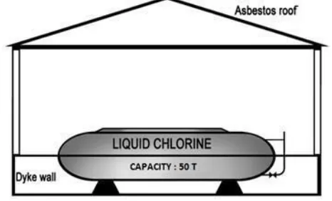
The storage tank is placed in a cement concrete dyke located in an open asbestos roofed container building as shown in Figure 1. The existing size of the dyke wall is 10m*4m*1m.
A partial pressure of 3Kg/cm2 and temperatures of -10 oC in liquid are maintained in the storage tank. The diameter and length of the horizontal cylindrical dished end tank are 250 mm and 8830mm respectively.
FIGURE. 1 EXISTING CHLORINE STORAGE FACILITY
3.MODIFICATIONS PROPOSED
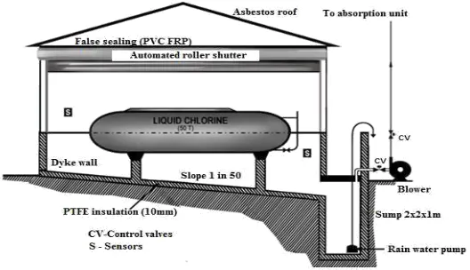
The proposed new mitigation system for the building of chlorine storage tank is shown in Figure 2. The existing dyke wall should be overlapped with materials having poor-heat transfer properties to reduce the rate of vaporization of chlorine. Poly tetra fluoro ethylene (PTFE) is one such material. It has a thermal conductivity of 0.25w/mK [7] and is suitable for liquid chlorine handling. The existing floor should be provided with a PTFE lining (shown in Fig. 2). Thickness of the lining is assumed as 10mm.
In the event of chlorine leakage the proposed mitigating system starts operating automatically. As soon as the leakage of chlorine is sensed by the sensor, the alarm device beeps and it communicates to the control room immediately. The Immediately Dangerous to Life or Health (IDLH) concentration for chlorine (10ppm) is considered as setting value of the sensor. The chlorine release from the storage tank is considered to be in liquid phase.
In liquid release, about 10% of chlorine spill will vaporize immediately [5].
4. RELEASE SCENARIO
The chlorine discharge is assumed to flow through the 20 mm diameter pipe connected at the dish end of the storage tank for sight glass fitting, which is 280mm from the base of the tank. It is assumed that the pipe gets broken at 50mm away from the tank. The quantity of chlorine considered for the study is 42.0 tones and the corresponding height of the liquid from the base is 1.4 meters. The worst case scenario considered is the incident that may occur at initial stage of transferring liquid chlorine from storage tank to truck container by using compressed air at 10 Kg/cm2.
Discharge Rate Calculation
The discharge rate is given by [9]
+ (1)
Where, - 3.14*10 -4
m2, 1,468 Kg/m3, - 3*10 5
N/m2 and 10*10 5
N/m2, - 1*10 5
N /m2, - 1.2m and - 9.81m/s2.
The discharge rate of chlorine from the pressurized tank will vary with time [10]. As the level of the liquid in the tank falls, the hydrostatic head, upstream pressure and, therefore, the rate of release will be reduced. This may lead to an overestimation of total quantity of discharge. To overcome this drawback, calculation of the discharge rate will, at best, take a set of piecewise constant pressure values with each piece as 1-10sec. The values of upstream pressure and liquid height above release point will vary in each set of discharge rate calculation. Table 1 shows the chlorine discharge in 10 seconds stepwise duration corresponding to the initial upstream pressure of 10*10
5
N/m2.
FIGURE. 2 PROPOSED MITIGATION SYSTEMS FOR CHLORINE STORAGE FACILITIES
Evaporation of the liquid pool
Vaporization from a pool is determined using total energy balance on the pool,
(2)
Where - 0.9412Kj/Kg, - 263 oK, - 239 oK and -288 kJ/kg.
Fraction of liquid entrained is given by [12]
TABLE. 1 DISCHARGE OF LIQUID CHLORINE IN 10 SECONDS INCREASE (P1, 10 *10
5
N/m2)
Time Pressure Pressure Liquid h* =
Liquid Vapour
Discharge
Volume Volume
P1 P2 height h-0.28
in the in the
2 2 3
(sec) (N/m ) (N/m ) h (m) (m) tank (m3) tank (m3) (m )
10 1000000.00 100000 1.4 1.12 28.67 11.99 0.07554
10 993739.33 100000 1.395 1.115 28.59 12.07 0.07529
10 987577.07 100000 1.392 1.112 28.52 12.14 0.07505
10 981510.13 100000 1.388 1.108 28.44 12.22 0.0748
10 975536.52 100000 1.384 1.104 28.37 12.29 0.07456
-- --- --- --- --- --- --- ---
-- --- --- --- --- --- --- ---
10 757106.15 100000 1.208 0.928 24.82 15.84 0.06505
10 754009.20 100000 1.205 0.925 24.76 15.90 0.0649
10 750944.41 100000 1.201 0.921 24.69 15.97 0.06475
10 747911.48 100000 1.199 0.919 24.63 16.03 0.06461
10 744909.46 100000 1.195 0.915 24.56 16.10 0.06446
600 4.17037
The mass fraction of liquid flashed can be represented as [11]
(3)
The vaporization rate of the pool is controlled by heat transfer from the ground (by conduction), the air (both by conduction and convection), and the sun (radiation). A number of useful references are available for estimating the evaporation rate from liquid pool [13, 14]. The mass transfer evaporation rate is given by [15]
5. DISPERSION OF CHLORINE
The dispersion calculations provide an estimate of the area affected and the average vapour concentrations expected.
The centerline ground level concentration is [16]
Where is the heat transfer coefficient of liquid chlorine (J/m2s oc) and which is given by
(15)
Where - assumed as 3.5 m/s and the stability class is F (conservative). The dispersion coefficients are obtained graphically or numerically using the downwind distance and stability category of the atmosphere [17].
6. DOSE-RESPONSE MODEL
The probit variable Y for gas exposure is [18]
(16)
Where values of , and are – 8.29, 0.92 and 2 respectively, and is the duration of exposure time in minutes. An exposure time of 10 minutes is assumed for the proposed storage facility and an exposure time of 76 minutes (average time for complete evaporation of liquid pool) for existing storage facility.
7. RESULTS AND DISCUSSION
In this research, rupture of pipe for sight glass fitting of a liquid chlorine storage tank is chosen for consequence assessment. The release time of liquid is considered as 10 minute.
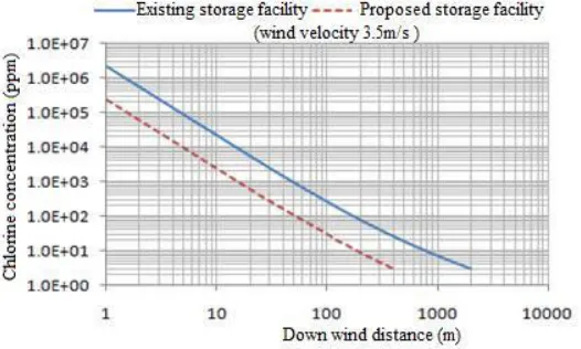
FIGURE. 3 CHLORINE CONCENTRATION WITH DOWN WIND DISTANCE
Total quantity of chlorine released in 10 minute is found to be 2.28m3 (3347 kg) and 4.17m3 (6121.56Kg) corresponding to the initial upstream pressure of 3*105 N/m2 and10*105 N/m2 respectively.
Equation 5 is used to calculate the mass of vapour flashed during release which is found to be 505.35 Kg and 924.35 Kg corresponding to the initial upstream pressure of 3*105 N/m2 and 10* 105 N/m2 respectively.
wind velocity of 3.5 m/s is considered for consequence assessment. The net evaporation rate in existing storage facility is found to be 1.152Kg/s where as it is 0.127 Kg/s in proposed storage facility.
Equation 15 is used to determine the chlorine concentration in the vicinity of the tank. The chlorine concentrations from different sources at different distances are calculated and the results are shown in Figure 3.
FIGURE.4 THE RELATIONSHIP BETWEEN DISTANCE AND FATALITY FOR EXISTING STORAGE FACILITY
For the existing storage facility, the percentage fatality is 82% at 100 m where as it is 10% at a distance of 200m.
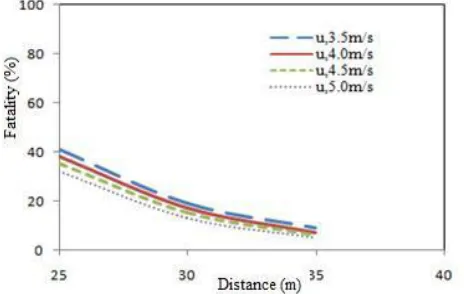
FIGURE. 5 THE RELATIONSHIP BETWEEN DISTANCE AND FATALITY FOR PROPOSED STORAGE FACILITY
For the proposed storage facility, the percentage fatality is 41% at 25 m where as it is 2% at a distance of 45 m. For the existing storage facility the minimum concentration of 3.06 ppm is estimated at a location of 2000 m which is outside the company premises.
8. CONCLUSIONS
proposed storage facility can be managed by on-site emergency response planning.
REFERENCES
[1] Allen, D.E and Thomason, C.S (2005). Fish Kill Investigation Graniteville Chlorine Spill Fish Kill Investigation in the Horse Creek System in Aiken County, SC January 7, 2005 through January 24,2005. Division of Wildlife and Freshwater Fisheries, South Carolina
Department of Natural Resources. EPA - 005706.
[2] Buckley, R.L. Hunter, C.H. Addis, R.P. and Parker, M.J. (2007). Modeling dispersion from toxic gas released after a train collision in Graniteville, SC.
Journal of Air & Waste Management Association, 57: 268-278.
[3] Jao-Jia Horng. Yi-Shu Lin. Chi-Min Shu. and Eric Tsai. (2005).Using consequence analysis on some chlorine operation hazards and their possible effects on neighborhoods in central Taiwan. Journal of Loss prevention in the process industries, 18: 474-480.
[4] Yu, Q. Zhang, Y. Wang, X..Ma, X.C. and Chen, L.M.(2009). Safety distance assessment of industrial toxic releases based on frequency and consequence: A case study in Shanghai, China. Journal of Hazardous Materials, 168: 955-961.
[5] Thomas F. O’Brien., Bommaraju, T.V. and Fumio Hine. (2005). Hand book of Chlor- Alkali Technology, Volume: 1 Fundamentals, Springer, 233, Springer street, New York, NY. pp – 1440-1442.
[6] Hendershot, D.C. Sussman, J.A. Winkler, G.E. and Lee Dill, G. (2006). Implementing Inherently Safer Design in an Existing Plant, Process Safety Progress, 25(1): 52- 57.
[7] Price, D.M. and Mark Jarret.(2002). Thermal conductivity of PTFE and PTFE composites, Thermochimica Acta 392-393: 231-236.
[8] Department of Transportation, (1980). “LNG Facilities, Federal Safety Standards” Federal Register, Vol.45, No.29, pp 9184-9237..
[9] Perry, R .and Green, D. (1984). Perry’s Chemical Engineering Handbook, 6th ed., McGraw-Hill, New York, NY.
[10] Hanna,S.R. Drivas, P.J. and Chang, J.C.(1996).Guidelines for use of Vapor Cloud
Dispersion Models, Second ed, AIChE/CCPS, 345 East, 47th street., New York, NY 10017.
[11] Crowl, D.A. and Louvar, J.F.(1990). Chemical Process Safety: Fundamentals with Applications, Englewood Cliffs, NJ, Prentice Hall (ISBN 0-13-129701-5).
[12] Cameron , I. and Raman, R. (2005).Process System Risk Management Vol.6, Elsevier Academic Press, San Diego, CA 92101-4495, USA.
[13] Kawamura, P.I.and Mackay, D. (1987). The Evaporation of Volatile Liquids. Journal of Hazardous Materials, 158: 343-64.
[14] AIChE/CCPS (1987a). Guidelines for use of Vapor Cloud Dispersion Models, New York, American Institute of Chemical Engineers,USA.
[15] Matthiesen, R.C. (1986). Estimating Chemical Exposure Levels in the Work place. Chemical Engineering Progress, 82(4): 30-34.
[16] Soman, A.R. Sundararaj, G. and Devadasan, S.R.(2012). Consequence assessment of chlorine release, Process Safety Progress, 31 (2):145-147.
[17] CCPS, (2000).Guidelines for Chemical Process Quantitative Risk Analysis, 2nd ed, AIChE, New York, USA.