Shape Optimization of Flexible Fixed Beam
K.S. Singh1, M.K. Meitei2 and S. Mahto3
B. Tech. Student, ME Dept., NERIST, Nirjuli, Arunachal Pradesh, India 1, 2
Assoc. Prof., ME Dept., NERIST, Nirjuli, Arunachal Pradesh, India 3
Abstract— In this work, shape optimization is carried out of a flexible fixed beam. Beam is considered under Euler-Bernoulli theory and finite element formulation is done for its dynamics analysis using Newmark’s scheme. Sequential quadratic programming (SQP) method is used to optimize the overall performance of the beam. Optimized fixed beam may be preferred in the real world applications for specific performance requirement.
Keywords—Euler-Bernoulli beam theory, flexible fixed beam, finite element method, shape optimization, sequential quadratic programming
I. INTRODUCTION
Conventional beams are comprised of high rigidity. Due to high rigidity, beams are generally heavy and bulky. Flexible beams have been a topic of investigation in several fields. Flexibility due to light weight of beams have several advantages (like less materials, transportable, etc). However, there are certain disadvantages associated with flexible beams, e.g. vibration due to low stiffness. Static deflection and vibration are the challenging tasks for flexible beam applications. To retain the advantages of flexible beam, it needs its optimal design.
Most of the researchers optimized the fundamental frequency of the cantilever beam or manipulator. Cranch and Adler [1] presented the closed-form solutions in term of Bessel’s functions for the natural frequencies. Unconstraint non-uniform beams with four kinds of rectangular cross-sections is considered for mode shapes analysis. Heidebrecht [2] determined the approximate natural frequencies and mode shapes of a non-uniform simply supported beam from frequency equation. Bailey [3] solved the frequency equation derived from Hamilton’s
principle to obtain natural frequencies of the non-uniform cantilever beams.
Elwany and Barr [4] presented work which maximizes the fundamental frequency for a given beam weight or equivalent beam weight minimization for a specific value of fundamental frequency. Olhoff and Perbery [5] determined the optimal design of a transversely vibrating thin elastic beam using cross-sectional area function as the design variable that maximizes the difference between two adjacent natural frequencies. Gupta and Murthy [6] studied the optimal design of uniform non-homogeneous beams under transverse vibration.
Optimum tapering of cantilever beam carrying tip mass is determined by Karihaloo and Niordson [6] to maximize fundamental frequency. Lio [7] developed a generalized method for the design of a cantilever beam of circular cross-section in flexural vibration. The beam is composed of two materials along the length. Wang [9] addressed optimum design of a single link manipulator to maximize its fundamental frequency. He formulated the design problem as a nonlinear eigenvalue problem using variational method. He demonstrated the increase of fundamental frequency as a result of optimization. Wang and Meirowitch [10] extended the work of Karihaloo and Niordson [7] to find substantial improvement in optimum shape through simplifying original analysis.
Wang and Russel [11] proposed minimax design method to construct the optimum shape under a finite range of tip loads. Xu and Ananthasuresh [12] employed sequential quadratic programming (SQP) method available in MATLAB for shape optimization of segment of compliant mechanism.
frequencies and dynamic response of the optimized beam. Dixit et al. [14] presented FEM model of single link flexible robotic manipulator for revolute and prismatic joint. They used SQP for optimizing beam shapes under different optimization conditions and compared its dynamic responses and fundamental frequencies.
From the above study, it is observed that most of the researchers contributed shape optimization for cantilever beam and rotating cantilever beam to improve certain objectives. There is no much research contribution in shape optimization of flexible fixed beam. In this work, authors considered three different optimization problems for shape optimization for comparative study.
II.MODELLING AND SOLUTION TECHNIQUE Flexible beams have significant transverse deflections. They behave as a nonlinear elastic beams and exhibit vibratory motions in transverse direction. Formulations are linearized for small transverse deflection due to bending motion under linear beam theory as a two-dimensional idealization. This simplified model is not suitable for modeling the dynamic behavior of flexible beam with large deflections.
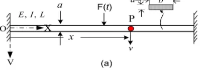
The finite element formulation has been described in Dixit [14]. It is described here for the sake of completeness. Figure 1(a) shows flexible fixed beam in which XOV represents the stationary co-ordinate frame. F represents the applied force at the mid-position of a beam, q represents the loading intensity (load per unit length) in the transverse plane and E, I, L, ρ, A and M represents the Young’s modulus, area moment of inertia, length, mass density, cross-sectional area and payload mass (at the centre) respectively. Motion of the manipulator is represented by fixed XOV co-ordinate frame. Beam is considered slender. So, transverse shear and rotary inertia effects are neglected allowing it to be treated as an Euler-Bernoulli beam. Beam is assumed to vibrate dominantly in vertical plane (XOV), neglecting gravity effects.
Fig. 1 (a) Configuration of flexible manipulator, (b) typical
finite element with four dof
Consider an infinitesimal link element P on the manipulator at a distance ‘x’ from the fixed end (left side). Position of the element P with respect to inertial frame of reference (XOV) after time ' 't and transverse deflection
( , )
v x t
is given by the position vector P( , )x v with respect to the fixed frame. From basic mechanics, equation of motion of the flexible beam may be written as2 2 2
2 2 2 0
v v
EI m q
x x t
(1)
where m (mass per unit length) and I are function of x and transverse load is the function of both x and t. The following geometry boundary conditions act at the fixed end sides:
( 0, ) 0
v x t & 0 0
v
x x
(2)
and
( , ) 0
v xL t & 0 L v
x x
. (3)
In the FEM formulation the beam is divided into elements, each element having four degrees of freedom as shown in Figure 1(b). In the figure,
v v v v
1,
2, ,
3 4 are the transverse deflection and slopes at the first and second nodes of the element. Transverse deflectionv
is expressed by the approximate functionv
e inside the element at point P. Then residual of Equation 6 is given by2 2 2
2 2 2
e e
v v
e
R EI m q
x x t
(4)
1 2
1 2 3 4
3 4
v v e
N N N N
v v v
(5)
where
x
is the local coordinate, h the element length and N1, N2, N3 and N4 are known as the Hermitian shape functions and Galerkin’s weight function We is approximated in the same fashion asv
eis defined as1 2 .
1 2 3 4
3 4
N N e
W W W W
N N W
(6)
Using Galerkin’s FEM approach, weak form of the differential equation for an element is given by
d 0. 0
h e e W R x
(7)
2 2 2 2
2 2 2 2
0 0
d 0
h h
e h e
v W v W v
W EI EI EI x
x x x x x x
22 d d 0.
0 0
e
h v h
m W x W q x
t
(8)
Using Equation 5 and 6, the Equation 8 becomes
1 1
2 2
1 2 3 4
3 3 0 4 4 d h N v N v
EI N N N N x
N v N v
1 1 2 21 2 3 4
3 3 0 4 4 d h N v N v
m N N N N x
N v N v
1 2 3 4 d0 Internal force vector.
N h N q x N N (9)
Effect payload mass is incorporated in the global mass matrix and stiffness matrix using Dirac-delta function as described by Dixit et al. [14]. Payload mass is defined μ
(ratio of tip mass to beam mass). Equation 9 can be expressed in matrix form:
.e e e
M v K v F
(10)where [Me], [Ke] and
Fe are the element mass matrix, stiffness matrix and element load vector. Structural damping of the beam is not considered for numerical study. After assembling element equations, the global system governing equation can be expressed as[M]{ }V [K V]{ }{ },F (11)
where [M] and [K] are the global mass and stiffness matrices respectively. Global load vector {F} and global nodal displacement vector {X} are given by
1 2 0 0... ...0 0 1 Tm n n
F F F F F F
(12)and
1 2 . . . n-1 T, nV
v v v v
(13)where n is number of nodes taken (21) and m is mid-position node no (11). Neglecting load vector, Equation 11 becomes standard eigenvalue problem, which is solved to obtain natural frequencies of the system. Newmark method is used to solve the Equation 11 to predict the dynamic behaviour of the beam. The Newmark integration scheme is basically the extension of the linear acceleration method. It is a constant average acceleration scheme. Using Newmark’s method, transverse deflection ( )v , slope ( )v
and its derivative are obtained.
III. OPTIMIZATION PROCEDURE
Three optimization problems are considered for the comparison of static and dynamic behavior of the flexible fixed beam system. Minimization of maximum dynamic tip deflection is considered as an objective for high speed operation of the robotic system. Minimization of mass of the uniform beam manipulator is kept constraints. General form of an optimization problem is expressed as
TABLE 1
DIFFERENT OPTIMIZATION PROBLEMS
Optimization Problem /Beam
referred
I (Beam-I) Minimization of static tip deflection
*
0
M M
II (Beam-II)
Maximization of fundamental beam
frequency
*
0
M M
III (Beam-III)
Minimization of maximum dynamic
tip deflection
*
0
M M
Permissible Bound : LB UB
X XX
where X
b1 b2 . . . bn
T is a design vector withbi indicating width of the ith finite element, f(X) indicates
the different objective function. Lower bounds (XL)and upper bound (XU)are the vectors of design variables respectively. M is the mass of the optimized manipulator,
*
M is the prescribed mass of the uniform. The MATLAB function “fmincon” uses sequential quadratic programming (SQP) technique for constrained optimization of nonlinear function.
III. RESULTS AND DISCUSSION
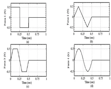
A comparative dynamic analysis has been carried out for shape optimized flexible fixed beam. For the numerical study, a beam having uniform width 10 mm, thickness 4 mm, length 1750 mm, mass 189.66 gm, Young’s modulus of elasticity 71 GPa is considered. Optimized beams are subjected to a sinusoidal force of amplitude 0.5 N-m (Figure 2d) at the mid-position of the beam.
Fig. 2 Excitation Force (a) Bang-bang, (b) Triangular, (c) Trapezoidal and (d) Sinusoidal
Fig. 3 Optimized shapes for different payloads mass ( )
(a) Beam-I, (b) Beam-II, (c) Beam-III
Fig. 4 All optimized shapes for payloads (µ=0)
Optimized shapes of the fixed beam as per the optimization problems defined in Equation 11 are plotted in Figure 3. There are different optimal shapes for different optimization problems. In optimization problem-I and II, there is almost no variations of optimal shapes for different payload masses, however there is for optimization problem-II.
These shapes give the optimal performance for that particular objective. Different optimized shapes under different optimization problems for payload mass
Fig. 5 Static beam deflection optimized at µ=0 due to 1N force at centre
For comparative static beam deflections, 1N static load is considered at the mid-position of the beam. Static beam deflections of uniform beam and optimized beams are plotted in Fig. 5. Optimized Beam-I and III are deflected lesser static beam deflection than that of uniform beam. As expected, Beam-I is least deflected. Beam-II is not improved for static beam deflection.
Fig. 6 Static beam deflection optimized at µ=0 due to 1N force at centre
Natural frequencies are important characteristics of any structural system. Fundamental frequencies of uniform beam and optimize beams are plotted in Fig. 6. All the optimized beams have higher fundamental frequency than that of uniform beam. However, optimized Beam-II enhanced the fundamental frequency of uniform beam maximum.
Fig. 7 Static beam deflection optimized at µ=0 due to 1N force at centre
Dynamic beam deflections due to sinusoidal force (0.5 sin 4t)are shown in Fig. 7. All optimized beams (at0)have minimum beam deflection than the uniform beam deflection for no payload mass cases. Beam-III is optimized for minimization of maximum dynamic beam deflection. Hence, it suppress the vibration maximum
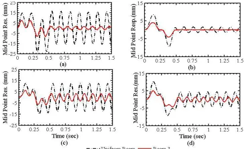
Fig. 8 Comparison of dynamic tip deflection due to bang-2 input torque, beam optimized at (a) µ=0, (b) µ=0.1,
(c) µ=0.3 & (d) µ=0.5
IV. CONCLUSION
In this work, shape optimization of flexible fixed beam is carried out through linear modeling. Thorough FE analysis has been conducted and successive SQP iteration scheme has been used to solve constrained optimum shape of the flexible fixed beam to optimize its static/dynamic performances.
There are different optimal shapes for different optimization problems. These optimum shapes give optimized overall performance for that particular payload. Beam optimized for higher payload always gives minimum of maximum dynamic beam deflection with respect to that of uniform beam manipulator for range of lower payloads but reverse is not necessarily true.
REFERENCES
[1] E.T. Cranch and A.A. Adler, “Bending vibration of variable cross-section beams”, J. of Applied Mechanics, ASME, vol.23(1), pp.103-108, 1956.
[2] A.C. Heidebvecht, “Vibration of non-uniform simply supported beams”, J . of Engineering Mechanics Division, proceeding of the ASCE, vol. 93(EM2), pp. 1-15, 1967.
[3] C.D. Bailey, “Direct analytical solution to non-uniform beam problem”, J. of Sound of Vibration, vol. 56(4), pp. 501-507, 1978.
[4] M.H.S. Elwany and Barr, A.D.S. Barr, "Optimal design of beams under flexural vibration", J. of Sound and Vibration, 88(2), pp. 175-195, 1983.
[5] N. Olhoff and R. Parbery, "Designing vibrating beams and rotating shafts for maximum difference between adjacent natural frequencies", J of Solid Structure, 30(1), pp. 63-75, 1984.
[6] V.K. Gupta and P.N. Murthy, "Optimal design of uniform non-homogeneous vibrating beams", J. of Sound and Vibration, 59(4), pp. 175-195, 1978.
[7] B.L Karihaloo and F.I. Niordson, “Optimum design of vibrating cantilever”, Journal of Optimization, Theory and Applications, vol. 11(6), pp. 638–654, 1973.
[8] Y.S. Lio, “A generalized method for the Optimal Design of Beams under Flexural Vibration”, Journal of Sound and Vibration, vol. 167(2), pp. 193–202, 1993.
[9] Fei-Yue Wang, “On the External Fundamental Frequencies of one Link Flexible Manipulators”, The International Journal of Robotics Research, vol. 13, pp. 162–170, 1994.
[10]F.Y. Wang and L. Meirovitch, “Optimum Design of Vibrating Cantilevers: A classical problem. Revisited”, Journal of Optimization Theory and Applications, vol. 84(3), pp. 635–652, 1995.
[11]F.Y. Wang, and J.L. Russel, “Optimum Shape Construction of Flexible Manipulators with Total Weight Constraint”, Systems, Man and Cybernetics, vol. 25(4), pp. 605–614, 1995.
[12]D. Xu, and G.K. Ananthasuresh, “Freeform Skeletal Shape Optimization of Compliant Mechanism”, Journal of Mechanical Design, vol. 125, pp. 253–261, 2003.
[13]S.K. Gunjal, and U.S. Dixit, “Vibration Analysis of Shape Optimized Rotating Cantilever Beam”, Engineering Optimization, vol. 39(1), pp. 105–123, 2007.