Robust Template-based Watermarking for DIBR 3D
Images
Wook-Hyung Kim1 ID, Jong-Uk Hou1, Han-Ul Jang1, and Heung-Kyu Lee1,*
1 School of Computing, Korea Advanced Institute of Science and Technology, Daejeon 305701, Korea;
1 2 3 4 5 6 7 8 9 10 11 12
13
[email protected](W.-H.K.);[email protected](J.-U.H.);[email protected](H.-U.J);
* Correspondence:[email protected]
Abstract:Severaldepthimagebasedrendering(DIBR)watermarkingmethodshavebeenproposed, buttheyhavevariousdrawbacks,suchasnon-blindness,lowimperceptibility,andvulnerabilityto signalorgeometricdistortion.ThispaperproposesatemplatebasedDIBRwatermarkingmethod thatovercomesthedrawbacksofpreviousmethods.Theproposedmethodexploitstwoproperties toresistDIBRattacks:thepixelisonlymovedhorizontallybyDIBR,andthesmallerblockisnot distortedbyDIBR.Theonedimensional(1D)discretecosinetransform(DCT)andcurveletdomains areadoptedtoutilizethesetwoproperties.Atemplateisinsertedinthecurveletdomaintorestorethe synchronizationerrorcausedbygeometricdistortion.Awatermarkisinsertedinthe1DDCTdomain toinsertanddetectamessagefromtheDIBRimage.Experimentalresultsoftheproposedmethod showhighimperceptibilityandrobustnesstovariousattacks,suchassignalandgeometricdistortions. TheproposedmethodisalsorobusttoDIBRdistortionandDIBRconfigurationadjustment,suchas depthimagepreprocessingandbaselinedistanceadjustment.
Keywords:Depth-image-basedrendering(DIBR);3Dcontent;curvelettransform;1D-discretecosine transform(1D-DCT);templatewatermark;DIBRwatermarking
14
1. Introduction 15
Three-dimensional (3D) content has been steadily increasing in popularity because of its excellent 16
lifelike appearance. With the recent development of 3D display technology, many new 3D applications 17
have appeared to maximize realism, such as head mounted displays, 360° virtual reality, and ultra-high 18
definition 3D content. Consequently, interest in 3D content and the 3D market itself have both increased 19
greatly. 20
Methods of representing 3D content are divided into stereo image recording (SIR) and 21
depth-image-based rendering (DIBR). SIR stores the left and right views (as human eyes do) and 22
provides a high-quality immersive view; however, this has many limitations, including large data size, 23
fixed depth, high cost, and difficulty with multiple camera settings. Meanwhile, DIBR is a rendering 24
method that creates various virtual viewpoint images using center and depth images[1–4]. The DIBR 25
method has two main advantages: 1) The DIBR system is able to easily save and transmit 3D content, 26
Watermarked
center image Watermark
Original center image
DIBR image (synthesized image)
Geometrically distorted DIBR image
Embed
watermark DIBR
Geometric distortion
Watermark extraction
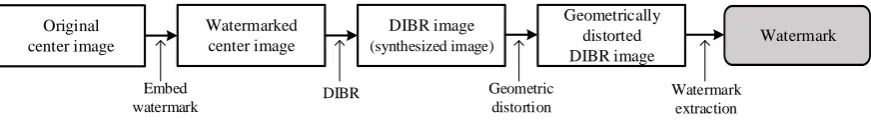
Figure 1.Watermark extraction scenario in DIBR image with geometric attack. Extraction is possible only if the watermark is survived both in the DIBR, which is a non-linear attack, and the geometric distortion, which is a linear attack.
since it allows us to adjust the 3D configuration. These advantages have led to DIBR technology being 28
employed in 2D-to-3D conversion [5–10] and auto-stereoscopic [11,12] and multi-view stereo[13–17] 29
that provide various viewpoints depending on the user’s position 30
Copyright protection techniques for DIBR content has received considerable attention due to 31
DBIRs important role and significant 3D content market growth. A typical copyright protection 32
technique is watermarking, but many conventional two-dimensional (2D) watermarking techniques 33
are difficult to apply to DIBR content. In the DIBR system, center image pixels are partially moved 34
along the horizontal axis with distance depending on the depth image, using a process called non-linear 35
geometric distortion. Watermarks inserted in the center image are strongly distorted and cannot be 36
extracted. 37
Hence, several watermarking methods have been proposed as being robust to the DIBR process. 38
Lin et al. proposed a method of embedding watermarks by predicting pixels’ moving distance[18]. 39
Protecting the center image and both the left and right images required superimposing and embedding 40
three watermarks. This method has a low bit error rate (BER) against the DIBR process and common 41
distortions, such as JPEG or additive noise. However, this method is vulnerable when the depth 42
information is modified, such as in depth image preprocessing or change of baseline distance, since the 43
moving distance for pixels during the DIBR process is predicted with unmodified depth information. 44
Additionally, this method is vulnerable to geometric attacks due to the characteristics of the discrete 45
cosine transform (DCT) domain. 46
Kim et al. suggested a watermarking method that employed quantization on dual tree complex 47
wavelet transform (DT-CWT) domain coefficients[19]. The method used directional coefficients that 48
were not significantly changed by the DIBR process. Row wise quantization was performed to provide 49
robustness to horizontal pixel shifts. The method showed robustness to DIBR; JPEG compression; 50
image scaling; and DIBR configuration adjustments, such as depth image preprocessing and baseline 51
distance changes. However, it was vulnerable to noise addition and geometric distortions. 52
Wang et al.[20], Miao et al.[21], and Cui et al.[22] proposed a DIBR watermarking method that 53
used the scale invariant feature transform (SIFT). The SIFT based-watermarking systems found similar 54
parts between the center image and the synthesized image using a SIFT descriptor and then inserted 55
the watermark into those parts. Because of the object matching with SIFT, these methods were robust to 56
DIBR distortion. Additionally, the methods showed high robustness to both general signal distortions 57
and geometric distortions. However, SIFT-based DIBR watermarking methods need SIFT descriptors 58
during watermark extraction. These methods cannot extract watermarks blindly; therefore, SIFT-based 59
watermarking methods are less practical than full-blind watermarking systems. 60
Asikuzzaman et al. proposed a DT-CWT based video watermarking method using color 61
channels[23,24]. The method inserted a watermark into the U channel of YUV color space and inserted 62
the same watermark rotated 180° into the V channel. They showed the method was robust to DIBR, 63
due to DT-CWT domain characteristics; and geometric attacks, such as scaling and rotation, since 64
the U and V channels suffer the same geometric transformation. However, if the image center was 65
changed due to attacks such as crop or translation, the watermark could not be detected, and under 66
geometric distortion it could only determine whether a watermark had been inserted or not, i.e., an 67
on/off switch. Therefore, its application was somewhat limited. 68
Various templates have been proposed that are robust against geometric attacks[25–28]. However, 69
these are only designed to be robust to linear distortions, such as affine transforms, and so are not 70
robust to DIBR, which is non-linear distortion as discussed above. 71
The results of previous works show that blind watermarks are very difficult to survive in 72
geometrically distorted DIBR images, because the watermark must be robust to both DIBR and 73
geometric attacks, as shown in Fig.1. The combination of non-linear and linear deformation severely 74
Center image
Depth image Depth image
(Blurred)
Center image Left image
Right image
Left image (Hole-filled)
Right image (Hole-filled)
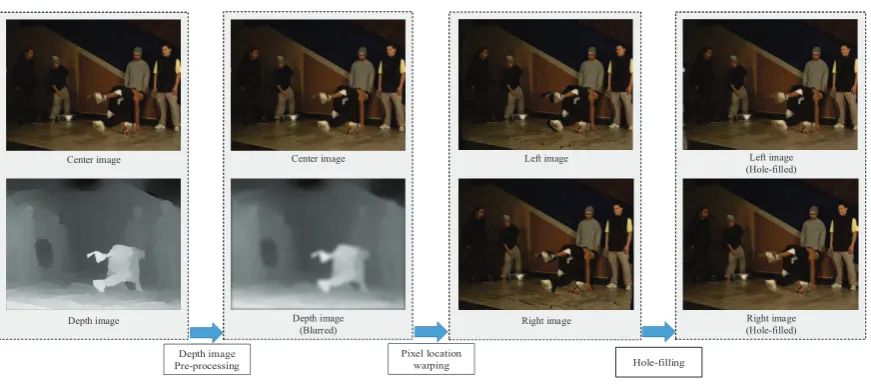
Figure 2.Overall process of DIBR system.
two watermarking methods that have different characteristics rather than using a single watermarking 76
method. 77
This paper proposes a blind template based watermarking system combining templates and 78
message watermarks. The role of the template is to restore geometric distortion without being destroyed 79
from DIBR attack. The template is inserted into the curvelet domain in the form of peak points, and 80
geometric distortion is estimated using the modified iterative closest point (ICP) method. The message 81
watermark inserts and detects messages in the DIBR image. The proposed message watermark is 82
inserted into the 1D-DCT domain and the message is extracted from the DIBR image after geometric 83
distortion recovery using the proposed template. The message watermark inserts the same information 84
along the horizontal direction in the 1D-DCT domain, and the inserted message watermark is invariant 85
to DIBR due to 1D-DCT linearity. 86
Experimental results showed that the proposed method has both high invisibility and robustness 87
against various attacks. It achieved excellent scores in visual quality tests and low BER for common 88
signal distortions, such as noise addition and JPEG compression. The watermarking system also 89
exhibited good robustness against geometric distortions, a point of vulnerability in previous 90
approaches, and excellent robustness against DIBR attacks and DIBR configuration adjustments. 91
This paper is organized as follows. Section2describes the DIBR system and curvelet transform, 92
which are fundamental techniques for the proposed scheme. Section3.1demonstrates the main idea 93
of the proposed watermarking method. The watermark embedding and extraction processes are 94
presented in Sections3.2and3.3, respectively, and the experimental results and conclusion are given 95
in Sections4and5, respectively. 96
2. Backgrounds 97
This section presents DIBR and the curvelet transform, fundamental techniques of the proposed 98
watermarking system. First, the DIBR process is briefly introduced and DIBR analysis is presented, 99
and then we provide an introduction to and analysis of the curvelet transform. 100
2.1. DIBR Process 101
The whole DIBR process is shown in Fig. 2. DIBR consists of three steps: depth image 102
preprocessing, pixel location warping, and hole filling. 103
Depth image preprocessing, the first step, improves the quality of the rendered image by reducing 104
the number of holes [29–31]. When the viewpoint is moved by the DIBR, an area where no pixel 105
large. Hence, the image quality can be improved by reducing the number of holes through depth 108
image smoothing. 109
Pixel location warping, the second step, changes the position of pixels along the horizontal direction, allowing users to feel a 3D effect. The warping equation is as follows,
xL=xC+
tx
2 × f Z
, xR=xC−
tx
2 × f Z
(1)
wherexCis the pixel position on thex-axis of the center image,xLandxRare the pixel positions on 110
thex-axis of the left view and the right view, respectively,txis the baseline distance, which means the 111
distance from the center axis to the left and right, f is the focal length, andZis the value of the depth 112
image. During warping, two or more pixels can overlap in one position. In this situation, the highestZ 113
value of a pixel has to be selected to prevent an unnatural image. 114
The last step is hole filling, which creates pixel values in holes caused by pixel location warping. 115
There are several hole filling techniques, such as interpolation and inpainting. This is a field that is 116
constantly studied in pursuit of a more natural image [4,32–34]. 117
2.2. Analysis of DIBR Attack 118
In the DIBR process, pixels are only translated horizontally, where the translation magnitude is 119
determined by the depth . Similar to the cover model being considered as a random, the depth image 120
is also close to a random signal[35], hence pixel’s moving distance can also be assumed to be random. 121
Consequently, the pixels move irregularly, unlike in common translation. Thus, the 2D transformed 122
domain coefficients are distorted by DIBR. 123
The watermark damage caused by DIBR can be confirmed by the average energy change of the 124
middle frequency at which the watermark is inserted, since the average energy is the basis of the 125
watermark embedding energy. 126
Table1shows the average energy change between center and synthesized DIBR image coefficients. DIBR parameters used in this test were as recommended by [3], and average energy change was defined as
MSE(O,S)
mean(O2) (2)
whereOandSare the transformed domain’s coefficients for the original and synthesized images, 127
respectively; and MSE is mean squared error. The various transform domain coefficients’ energy is 128
severely impaired by DIBR. Therefore, the watermark energy, inserted into the transform domain’s 129
coefficients, is also damaged, and watermarks damaged by more than 40% are difficult to detect. 130
However, the average energy change of the haar discrete wavelet transform (DWT) is reduced to 131
4% if the distorted coefficients are matched with the undistorted coefficients using the depth image. 132
This is because the wavelet series represent the frequency information of the small spatial block, such 133
as 2×2, 4×4,· · ·. 134
If the image is divided into small blocks, some of these will be undistorted, since the depth is 135
similar between adjacent pixels within an object. If all depth values are the same in the block, pixel 136
moving distances are all the same. DIBR is treated like a common translation for this case. Smaller 137
block size implies greater percentage uncorrupted blocks, as shown in Table2for the example of 1800 138
synthesized DIBR images. Similar to the previous average energy change test, this test also used the 139
recommended DIBR parameters from [3]. 140
Since DCT and discrete Fourier transform (DFT) express a global frequency that does not include 141
spatial information, the amount of average energy change after matching is still high. In other words, 142
it can be seen that the magnitude of the coefficients is damaged in DCT and DFT, but the magnitude of 143
Table 1.Average energy change between coefficients of center and synthesized images.
2D DCT 2D DFT(mag) 2D DWT (haar)
Average Unmatched 209% 39% 215%
energy change Matched 207% 40% 4%
Table 2.Average percentage of undistorted blocks after DIBR
Block size
5×5 10×10 20×20 40×40
Undistorted blocks(%) 94.32 85.68 70.67 48.35
In summary, the following two properties of DIBR can be identified: 1) the pixel is moved only 145
in the horizontal direction and the moving distance is determined by the depth; 2) the percentage of 146
undistorted blocks is high with a small block size. Due to the second property, the wavelet series are 147
robust to DIBR. 148
2.3. Curvelet Transform 149
The curvelet transform is a multi-scale decomposition-like wavelet transform, and the curvelet represents the curve shape for the various directions in the spatial domain[36–39]. The curvelet transform is developed to improve on the limitation of wavelet-based transforms and can represent edges more efficiently than conventional wavelet-based transforms. Moreover, curvelet bases cover all frequencies in contrast to other directional multi-scale transforms, such as the Gabor and Ridgelet transforms[40]. The curvelet transform is expressed as follows,
C(g,l,k):=hf,ϕg,l,ki=
Z
R2 f(x)ϕg,l,kdx
= 1
(2π)2
Z ˆ
f(ω)Ug(Rθlω)e
ihx(kg,l),ωidω,
(3)
Ug(r,θ) =2−3g/4W(2−gr)V
2bg/2cθ
2π
, (4)
In (3),Cis the curvelet coefficient,g=0, 1, 2, ... is the scale parameter,lis the rotation parameter, and 150
k= (k1,k2)is the translation parameter.Ugis a “wedge”-shaped frequency window represented in 151
(4).Rθ is the rotation operator andθl = 2π·2
−bg/2c·l. In (4),W andVare the radial and angular
152
windows, respectively. 153
The curvelet is illustrated in Fig.3. Figure3(a) illustrates the tiling of the curvelet in the frequency 154
domain, and the curvelet shape in several directions and scales in the spatial domain are shown in Fig. 155
3(b)–(d). 156
As shown in Eq. (3) and Fig.3, the curvelet represents frequency information of a small spatial 157
block similar, so the curvelet is also not distorted by DIBR. In addition, energy conservation is better 158
with the curvelet transform than with conventional haar DWT when image rotation occurs[41]. For 159
example, when the image rotates 10 degrees, the energy inserted into haar DWT is reduced to 50%, 160
but that inserted into the curvelet is maintained up to 85%. In case of scaling attack, energy is well 161
maintained in most DWT. 162
In summary, the curvelet transform is suitable for use as a template due to its robustness to DIBR 163
(b) (c)
(d)
(a)
(b)
100 200 300 400 500
50
100
150
200
250
300
350
400
450
500
(c)
100 200 300 400 500
50
100
150
200
250
300
350
400
450
500
(d)
Figure 3.Curvelet in the frequency and spatial domain. (a) Curvelet tiling of the frequency domain; (b)–(d) Curvelets for various scales and directions in the spatial domain. Curvelets are drawn on k1=w/2 andk2=h/2.
Template embedding
Message watermark embedding Original image Watermarked image
Template key Split image into
template and message blocks
Message key & Message
(a)
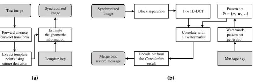
Message watermark extraction Test image Extracted message
Template key Template decoding
and image synchronization
Split synchronized image
into blocks
Message key
(b)
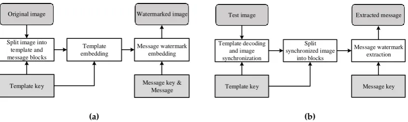
Figure 4.Watermarking process overview. (a) Embedding process; (b) Extraction process.
3. Proposed Method 165
3.1. Main Idea of Proposed Method 166
The overall flow of watermark embedding/extraction is shown in Fig.4. As shown, the proposed 167
watermarking system consists of a template and message watermark. This section describes the 168
characteristics and roles of the template and message. 169
The DIBR watermarking system must be robust to both DIBR and geometric attacks, as shown 170
in Fig.1. The proposed method inserts a template into a curvelet domain robust against DIBR and 171
geometric distortions. The inserted template enables restoring the image from geometric distortion 172
without being destroyed by DIBR. Geometric distortion can be restored by inserting the template in 173
peak point form and matching detected peaks with ground-truth positions, which can be obtained 174
from the template key in the detection step. 175
However, although the peak matching method can recover global geometric distortion that occurs 176
across the entire image, DIBR distortion cannot be recovered because it is treated as horizontal error. 177
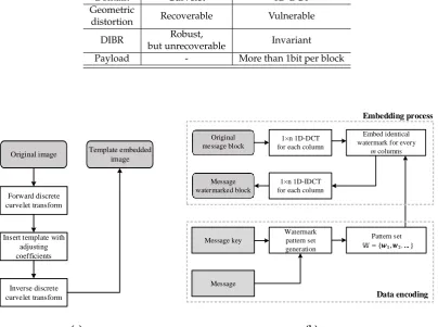
Table 3.The roles of template and message watermark.
Template Message watermark
Domain Curvelet 1D-DCT
Geometric
distortion Recoverable Vulnerable
DIBR Robust,
but unrecoverable Invariant
Payload - More than 1bit per block
Original image Template embedded image
Inverse discrete curvelet transform Insert template with
adjusting coefficients Forward discrete curvelet transform
(a)
1×n 1D-DCT for each column
Embed identical watermark for every
m columns
1×n 1D-IDCT for each column
Message
Watermark pattern set generation
Pattern set Message key
Original message block
Message watermarked block
Data encoding Embedding process
(b)
Figure 5.Detailed embedding process. (a) Template embedding process; (b) Message watermark embedding process.
designed an invariant message watermarking technique against DIBR, where DIBR deformations that 179
cannot be restored by the template are handled by the message watermark. Message watermarks 180
without templates are vulnerable to geometric attacks, but combining template and message watermark 181
advantages allows a robust DIBR watermarking system. 182
In summary, the template and message in the proposed watermarking system complement 183
each other’s weaknesses. The curvelet with robustness to DIBR is utilized as a template to restore 184
images from geometric attacks. The message watermark inserted in the 1D-DCT domain resolves the 185
unrecovered damage caused by DIBR. The message watermark itself is not robust to geometric attacks, 186
but images that have suffered geometric attacks can be restored using templates. The roles of templates 187
and message watermarks are summarized in Table3. 188
3.2. Proposed Watermark Embedding Method 189
This section gives a detailed description of the proposed watermarking procedure. The whole 190
embedding process is presented in Fig.5. 191
3.2.1. Block Separation 192
If the template and the message watermark are inserted at the same position, the signals interfere 193
with each other, and the robustness is degraded. To avoid overlapped insertion, the image is spatialy 194
divided intoM×Nblocks, as shown in Fig.6. The set of blocks is defined asB, and the template and 195
: Template
: Message watermark Template
key
Random binary code generation
M× N binary matrix (K)
Figure 6.Example of template and message watermark block placement in spatial domain.
m
n
3 m
3 2m
3 2m 3 m
Figure 7.Insert four peak points into one template block. The points are inserted at the third division point so that the intervals are the same.
A random binary code is generated using the key, and this code is used to generate a 2D binary 197
matrix,K, of sizeM×Nsize, which determines whether each block is a template or watermark block 198
in an image divided into blocks. To match the number of template blocks with the number of message 199
watermarks, average (K) should be 0.5. 200
The following rules distinguish the roles of the blocks.
B(x,y) = (
Template block, ifK(x,y) =1
Watermark block, ifK(x,y) =0 (5) where,xandyare the horizontal and vertical coordinates ofBandK, 0≤x<M, and 0≤y<N. 201
3.2.2. Template Embedding 202
Since the curvelet coefficients contain spatial information, the template block position can be 203
extracted from the curvelet coefficients. Therefore, the entire image is transformed into the curvelet 204
domain without requiring a block based curvelet transform. We then insert the peak point templates 205
into the curvelet coefficients. 206
As shown in Fig.7, four peak points are inserted into one template block. If the number of peak 207
points is too small, the robustness drops, and if there are too many points, the visual quality drops. 208
Experimentally, four points were appropriate. 209
The template embedding process is divided into three steps: 210
a) Forward curvelet transform: The forward curvelet transform is applied to the whole image. 211
b) Peak points insertion: Select two directions of a curvelet,l1andl2, with scale valueg.l1and
212
l2are selected such that they differ by 90°, to increase detection rate by corner detection in the
213
template extraction step, andgshould be selected to be a middle frequency, as a compromise 214
between invisibility and robustness. As discussed above, four peak points are inserted into one 215
Cm(g,l1,k) =C(g,l1,k)·αt+βt
Cm(g,l2,k) =C(g,l2,k)·αt+βt
(6)
whereCmis the modified curvelet coefficient,Cis the original curvelet coefficient,αtandβtis 217
the strength of the inserted template, andkis the location of the template point. 218
c) Inverse curvelet transform: The inverse curvelet transform is applied to the modified coefficients. 219
3.2.3. Message Watermark Embedding 220
The message is inserted into the 1D-DCT domain using the spread spectrum method[42]. If a watermark having the same information in the horizontal direction is inserted into the 1D-DCT, invariance can be obtained against DIBR due to the first property in Section2.2. The 1D-DCT watermark insertion equation is as follows,
DCT(Ii0:) =DCT(Ii:) +w, (7)
wherei = 1, 2, ...,m,w = [w1,w2, ...wn]T is the watermark signal, andm,nare the horizontal and 221
vertical sizes of the block, respectively.Ii:denotes thei-th column of the original block,Ii0:denotes the
222
i-th column of the watermarked block, andDCTdenotes the 1D-DCT. 223
The DIBR attack is applied in the spatial domain, not in the transformed domain. Therefore, the inverse DCT (IDCT) is performed to check the change of the inserted watermark in the spatial domain. Using the IDCT, Eq. (7) can be rewritten according to linearity of the DCT as follows,
Ii0:=IDCT(DCT(Ii0:))
=IDCT(DCT(Ii:) +w) =Ii:+IDCT(w)
=Ii:+v,
(8)
wherev= [v1,v2, ...,vn]Tdenotes the inverse transformed watermark. 224
The signalvis inserted as the same information in all columns of the spatial domain. This means that the embedded patterns from thej-th row have the samevjsignal. Therefore, embedded watermark vhas the following DIBR invariance,
D([v,v, ...,v]) =
v1 v1 . . . v1
v2 v2 . . . v2
..
. ... . .. ... vn vn . . . vn
= [v,v, ...,v] (9)
whereD(·)is the DIBR process described in Section2.1. 225
Since DIBR only translates pixels in the horizontal direction,vis not deformed. Therefore, the watermark can be extracted in the frequency domain as follows,
DCT(D(Ii0:)) =DCT(D(Ii:+v))
=DCT(D(Ii:) +D(v))
=DCT(D(Ii:) +v)
=DCT(D(Ii:)) +DCT(v)
=DCT(D(Ii:)) +w.
(10)
Hencewcan be extracted in the frequency domain without being damaged by DIBR in extraction 226
Forward discrete curvelet transform
Test image Synchronized image
Extract template points using corner detection
Estimate the geometric
information
Template key
(a)
Watermark pattern set generation Pattern set
Message key Synchronized
image
Merge bits, restore message
1×n 1D-DCT
Correlate with all watermarks Block separation
Decode bit from the Correlation
result
(b)
Figure 8.Proposed extraction process. (a) Template decoding and image recovery from geometric distortions, (b) Message watermark extraction.
To compensate for capacity decrease caused by template insertion, a data coding technique can be 228
utilized to insert more than 1 bit per block [35]. The message watermark embedding process is divided 229
into four steps as follows. 230
a) Column-by-column 1D-DCT: Each column of the message block is transformed by 1D-DCT. 231
b) Data encoding: A pseudo random watermark pattern set (i.e., a set of watermark patterns) is 232
generated. The length of the set is determined by the user, and the capacity of the block is 233
determined according to the length. For example, to represent 4 bits of information per block, 16 234
(i.e., 24) unique watermark patterns are generated[43]. 235
c) Watermark embedding: The proposed method embeds the watermark based on the spread-spectrum[44]. The generated watermark pattern set wb = {wb1,wb2, . . . ,wbL} is
embedded into the middle frequency of the DCT signal s = {s1,s2, . . . ,sL} compromising
both robustness and invisibility. The embedding equation is as follows,
s0i =si+αm|si|wbi (11)
whereiis the block column, 1≤i≤L,Lis the length of the watermark signal,s={s1,s2, . . . ,sL} 236
is the original signal,s0=
s01,s02, ...,s0L is the watermarked signal,αmis the message watermark 237
strength,wbLis the watermark pattern, andbis the message inserted into the block. For example, 238
ifb=7 (111 in binary form), the message inserted in the block is 111 (in this case, pseudo-random 239
pattern set length = 23). The embedding step (11) is repeated for all columns in the block. 240
d) 1D-IDCT: The watermarked block is reconstructed by 1D-IDCT. 241
3.3. Proposed Watermark Extraction Method 242
This section describes the details of the proposed watermark extraction method. The overall 243
process is illustrated in Fig.8. Before extracting the messages, the image must be synchronized using a 244
template. 245
3.3.1. Template Decoding 246
a) Forward curvelet transform: The curvelet transform is applied to the test image. 247
b) Extract template points using corner detection: A peak was inserted into thel1andl2pair in the
248
embedding step, with 90° difference at each template point. Due to curvelet filter characteristics, 249
the peak point spreads in a straight line in the corresponding direction. Therefore, the peak point 250
is represented by an “X” shape when only coefficients ofl1andl2are extracted, as shown in
251
Fig.9, and can be found by corner detection. This paper employed Harris corner detection, but 252
(a) (b)
Figure 9.Template extraction results (a) for one template block; (b) for whole rotated image. Red dots are points detected by corner detection.
c) Estimate degree of geometric deformation by exploiting modified ICP: The ICP method estimates 254
the parameters of geometric distortion when there is no matching information of two point 255
clouds. This method assumes that the closest points between the two point clouds match each 256
other and repeats the process of minimizing the error[45]. 257
This paper modifies the ICP to suit the problem in need of solving. Since the DIBR image has an 258
error in the horizontal information, the weight of the horizontal distance error is set to 1/2. 259
Geometric distortion parameters are estimated using the modified ICP method, comparing 260
detected corner points with template point ground truth. The template ground truth can be 261
generated using the key as in the embedding step. 262
d) Recover the test image using the estimated geometric distortion parameters. 263
If the degree of geometric transformation is large, the direction in which the template was inserted 264
may have changed. For example, if the image was significantly rotated, the template inserted in 265
direction pairsl1andl2is moved to the direction pairsl1+1 andl2+1. In this case, the template
266
decoding process is repeated for all direction pairs, and the estimated geometric parameters with the 267
lowest ICP error is used. 268
3.3.2. Message Watermark Extraction 269
The message is extracted from the image recovered by template. Message extraction consists of 270
six steps: 271
a) Split synchronized image into blocks: Divide the recovered image into blocks as in the embedding 272
step. 273
b) Column-by-column 1D-DCT: The same process applied in the embedding step is applied. 274
c) Correlation: The correlation is conducted as follows,
Corr(b) = s
0·w
b
L =
1 L
L
∑
i=1s0i·wbi (12)
The notations are identical to those in the embedding step. 275
e) Bit decoding: Bits are decoded from the correlation result. For example, if correlation value 276
withw3iis the highest, then the bit decoded from theith column is 011. The length of the bit is 277
determined by the length of the watermark pattern set, and in this case, watermark pattern set 278
length = 23. Different bits may be decoded for each column, and the majority voting method is 279
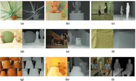
(a) (b) (c)
(d) (e) (f)
(g) (h) (i)
Figure 10.Test image sets. (a) aloe; (b) baby; (c) ballet; (d) bowling; (e) breakdancers; (f) cloth; (g) flowerpot; (h) lampshade; (i) interview.
f) Restore messages by merging the bits: The messages are recovered by merging the bits extracted 281
from each message block. 282
4. Experimental Results 283
This section evaluates the proposed method performance in terms of imperceptibility and 284
robustness to various distortions. The proposed method was compared with other blind DIBR image 285
watermarking systems, specifically Lin’s method [18] and Kim’s method[19]. The bit capacity of all 286
methods was set to 64. 287
4.1. Experiment Setting 288
The test image sets were obtained from Heinrich Hertz Institute[46], Middlebury[47–50], and 289
Microsoft Research 3D Video Datasets[51]. Fig.10shows pairs of center and depth images of the test 290
image sets. They have various resolutions from 900×720 to 1800×1500. The total number of images 291
used in the experiment was about 1800. 292
The DIBR parameters are set to focal length f =1 and baseline distancetx =5% of the image 293
width, which are the recommended value for comfortable viewing conditions. Linear interpolation is 294
used as hole filling for simplicity and without loss of generality. 295
For Lin’s method, block size was set from 100×100 to 200×200 to match embedding capacity 296
with other methods. Watermark strength was set asα= 1, watermark pattern length = 5120, and the 297
beginning of the embedding position is the 2560-th coefficient of the zigzag scan order in the DCT 298
domain. 299
For Kim’s method, block size was set to (w/8)×(h/8). The weighting factor for coefficient 300
magnitude was set asW= 450, maximum quantization levelmaxBit= 2, and minimum difference
301
between paired coefficientserrMin= 8. These values are demonstrated in [19]. 302
In the proposed method, the size of each block is set set to (w/8)×(h/8). In the template embedding 303
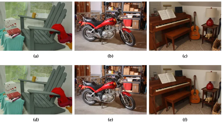
(a) (b) (c)
(d) (e) (f)
Figure 11.(a)–(c) Original ’adirondack’, ’motorcycle’ and ’piano’; (d)–(f) Watermarked ’adirondack’, ’motorcycle’ and ’piano’ by the proposed method.
Table 4.Average PSNR and SSIM.
PSNR SSIM
Proposed method 50.03 0.9942
Lin’s method 45.12 0.9936
Kim’s method 44.02 0.9878
embedding process,αmis set to 0.5, the length of the watermark pattern is 40, and the start of the 305
embedding position is the 45th coefficient of 1D-DCT. 306
4.2. Image Quality 307
As shown in Fig.11, the quality degradation of the watermarked image is not noticeable. For more 308
accurate image quality measurements, the peak signal-to-noise ratio (PSNR) and structure similarity 309
(SSIM)[52] were measured. The average PSNR and SSIM are shown in Table4. 310
Lin’s method has a lower PSNR despite it exploiting a spread spectrum-based watermarking 311
method that is similar to the proposed method. Since the 2D-DCT is not invariant to DIBR, the Lin’s 312
method must insert three watermarks in a superimposed manner in order to protect left, right, and 313
center image. For this reason, the inserted watermark energy is very large. 314
In Kim’s method, the images are seriously blurred, because this method cuts the coefficient off 315
excessively. As a result, both PSNR and SSIM values were low. 316
The proposed method increases imperceptibility by taking advantage of the curvelet and 1D-DCT, 317
which are robust against DIBR. Due to this robustness, the proposed method does not require excessive 318
insertion of the watermark. In particular, the message watermark using the 1D-DCT does not require 319
watermark insertion in a superimposed manner, so the insertion energy can be reduced to about 320
one-third as compared with the 2D-DCT. In addition, since the template and the message can be inserted 321
into different blocks after dividing the block, it is possible to prevent the invisibility degradation caused 322
by the overlapping of templates and message watermarks. For these reasons, PSNR outperforms the 323
Center image Left image Right image
Proposed method 0.002 0.002 0.002
Lin’s method 0.000 0.002 0.004
Kim’s method 0.006 0.008 0.009
Table 6.Average BER of synthesized images using preprocessed depth image.
Left image (Preprocessed depth)
Right image (Preprocessed depth)
Proposed method 0.002 0.002
Lin’s method 0.003 0.007
Kim’s method 0.008 0.009
4.3. Robustness against DIBR 325
Table5shows the results of a DIBR attack. All three methods have low BER against the DIBR 326
attack. Since Lin’s method inserts multiple watermarks, the BER is slightly higher on the right image. 327
The previously inserted watermark (right watermark) was disturbed by the later inserted watermarks 328
(left and center watermarks). 329
The major advantage of the DIBR process is that DIBR configurations can be adjusted to suit a 330
user’s needs. As described in Section2.1, the user can preprocess the depth image to increase the 331
rendered image quality. Table6shows robustness results for synthesized images with a preprocessed 332
depth image. Unlike other methods, Lin’s method raised the BER. This result shows that Lin’s method 333
is susceptible to the shift distance of the pixel, because the left and right watermarks were inserted by 334
predicting the shift distance of the pixels. 335
Baseline distance is another DIBR configuration aspect. Various viewpoints of an image can be 336
synthesized depending on the baseline distance change. Figure12shows average BER where the 337
baseline distance is adjusted from 1 to 10%. Lin’s method increases BER for the same reason as in-depth 338
image preprocessing, whereas Kim’s and the proposed method do not increase BER in the baseline 339
distance adjustment. 340
4.4. Robustness against Signal Distortion 341
Tables7and8show the average BER for the signal distorted center, left, and right images, and 342
Fig.13illustrates the average BER for the signal distorted right image. 343
For additive noise, Lin’s method has the best performance, and the proposed method has a slightly 344
higher BER than Lin’s method. However, additive Gaussian noise with a variance of 2000 is a very 345
1 2 3 4 5 6 7 8 9
Baseline distance(%)
0 0.1 0.2 0.3 0.4 0.5 0.6 0.7
BER
Proposed Lin Kim
Table 7.Average BER for Gaussian noise attack
Noise Proposed Lin Kim
var. Left Center Right Left Center Right Left Center Right
10 0.00 0.00 0.00 0.00 0.00 0.00 0.04 0.03 0.04
40 0.00 0.00 0.00 0.00 0.00 0.00 0.12 0.09 0.111
300 0.01 0.01 0.01 0.00 0.00 0.00 0.38 0.36 0.38
1250 0.04 0.04 0.05 0.02 0.02 0.02 0.54 0.54 0.55
Table 8.Average BER for JPEG attack
Quality Proposed Lin Kim
factor Left Center Right Left Center Right Left Center Right
90 0.00 0.00 0.00 0.00 0.00 0.00 0.02 0.01 0.02
60 0.01 0.01 0.01 0.00 0.00 0.00 0.22 0.20 0.22
30 0.10 0.09 0.10 0.09 0.08 0.10 0.35 0.33 0.35
100 101 102 103
Noise variance
0 0.1 0.2 0.3 0.4 0.5 0.6 0.7
BER
Proposed Lin Kim
(a)
30 40 50 60 70 80 90 100
JPEG quality factor
0 0.05 0.1 0.15 0.2 0.25 0.3 0.35
BER
Proposed Lin Kim
(b)
0.6 0.8 1 1.2 1.4 1.6 1.8 2
Scaling factor
0 0.1 0.2 0.3 0.4 0.5 0.6 0.7
BER
Proposed Lin Kim
(a)
5 10 15 20 25 30 35 40 45
Rotation degree(°)
0 0.1 0.2 0.3 0.4 0.5 0.6 0.7
BER
Proposed Lin Kim
(b)
5 10 15 20 25 30 35
Translation(%)
0 0.1 0.2 0.3 0.4 0.5 0.6 0.7
BER
Proposed Lin Kim
(c)
0.05 0.1 0.15 0.2 0.25 0.3
Shearing factor
0 0.1 0.2 0.3 0.4 0.5 0.6 0.7
BER
Proposed Lin Kim
(d)
Figure 14.Average BER for geometric distortion. This experiment was conducted on the right image. (a) image size scaling; (b) image rotation; (c) image translation; (d) image shearing
Table 9.Average BER for scaling attack
Scaling Proposed Lin Kim
factor Left Center Right Left Center Right Left Center Right
0.6 0.01 0.01 0.02 0.48 0.49 0.49 0.08 0.01 0.10
0.8 0.02 0.01 0.02 0.47 0.50 0.52 0.01 0.02 0.03
1.4 0.09 0.06 0.08 0.52 0.51 0.49 0.01 0.01 0.01
2.0 0.04 0.03 0.04 0.49 0.50 0.50 0.02 0.02 0.02
severe attack and such a large amount of noise barely occurs. Considering this, the proposed method 346
is robust enough to additive noise. 347
For JPEG compression, the proposed method has a slightly higher BER than Lin’s method. 348
However, since the proposed method exhibits error < 0.1 for JPEG quality factor 30, which is very large 349
compression, it can be considered sufficiently strong against a JPEG attack. 350
Meanwhile, Kim’s method is more vulnerable to signal distortion than the other methods, since 351
the quantized DT-CWT coefficients are greatly affected by the signal distortion. 352
4.5. Robustness against Geometric Distortion 353
A robustness test against geometric distortion was also conducted with center, left, and right 354
images. Tables9–12show the average BER for the geometrically distorted center, left, and right images, 355
and Fig.14illustrates the average BER for the geometrically distorted right image. 356
Lin’s method does not show good results against geometric distortion, because this method 357
Table 10.Average BER for rotation attack
Rotation Proposed Lin Kim
degree Left Center Right Left Center Right Left Center Right
10 0.09 0.05 0.10 0.45 0.54 0.51 0.43 0.41 0.42
20 0.10 0.07 0.09 0.52 0.50 0.49 0.54 0.55 0.51
30 0.09 0.06 0.09 0.50 0.53 0.53 0.52 0.54 0.54
40 0.11 0.08 0.12 0.55 0.56 0.50 0.50 0.55 0.54
Table 11.Average BER for translation attack
Transl- Proposed Lin Kim
ation(%) Left Center Right Left Center Right Left Center Right
10 0.08 0.06 0.09 0.54 0.51 0.51 0.24 0.22 0.22
20 0.07 0.05 0.08 0.53 0.50 0.53 0.55 0.55 0.55
30 0.11 0.07 0.12 0.49 0.47 0.50 0.53 0.53 0.53
Table 12.Average BER for shearing attack
Shearing Proposed Lin Kim
factor Left Center Right Left Center Right Left Center Right
0.1 0.03 0.02 0.02 0.54 0.51 0.52 0.24 0.22 0.22
0.2 0.03 0.03 0.03 0.48 0.53 0.49 0.53 0.50 0.51
0.3 0.05 0.05 0.05 0.50 0.51 0.47 0.52 0.53 0.56
Table 13.Average BER of proposed method for combination geometric distortion. The experiment was conducted to the synthesized right image.
Translation(%) Rotation° Scaling
factor
Rotation° Scaling
factor
Translation(%)
3 6 9 3 6 9 7 14 21
5 0.11 0.11 0.11 0.8 0.13 0.10 0.12 0.8 0.13 0.12 0.13
10 0.12 0.12 0.12 0.9 0.10 0.09 0.09 0.9 0.12 0.11 0.11
15 0.11 0.12 0.12 1.1 0.17 0.17 0.18 1.1 0.13 0.12 0.13
shearing. This method does not lose synchronization information in scaling. However, the rotation, 360
translation, and shearing attacks break the block synchronization. This is because the block size is 361
specified as the ratio of the image, such as(width/M)×(height/N). 362
The proposed method shows good performance on this test, because it utilizes a template robust 363
to geometric attacks. Since the images were recovered from geometric distortion using this template, 364
the message watermark has a low error. 365
Experiments were also conducted on the combination of geometric distortion in the proposed 366
method. This experiments were conducted by combining two of rotation, translation, and scaling, and 367
the results are shown in Table13. Rotation with translation and scaling with translation show good 368
results. However, when rotation and scaling occur at the same time, the watermark signal is greatly 369
weakened, so the error is higher than with other geometric combination attacks. 370
5. Conclusion 371
Due to the advent of new 3D applications, DIBR has taken on an important role in 3D content. 372
To protect the copyright of such content, this paper proposed a template-based DIBR watermarking 373
system. Ensuring robustness against geometric attacks in rendered images requires that watermarks 374
should be robust to both DIBR and geometric attacks. In order to have robustness to a combination 375
of linear and non-linear attacks, a watermarking system was designed by combining two methods: 376
template and message watermark. Inserting a template into the curvelet domain robust to DIBR 377
allowed this method restore the geometrically distorted image. Then, the message was extracted 378
using a 1D-DCT message watermarking method that was invariant to the DIBR. In experimental 379
results, the proposed method showed high image quality. In terms of robustness, it had low BER 380
to DIBR configuration adjustment as well as standard configured DIBR. Additionally, the results 381
showed that the proposed method is very robust against noise addition and JPEG compression. For 382
geometric distortion, such as scaling, rotation, translation, and shearing, good performance was also 383
demonstrated. However, this method still does not consider the robustness of video coding, which 384
is often used in 3D video, such as high-efficiency video coding (HEVC). Therefore, future work will 385
focus on extending this method to 3D videos. 386
Author Contributions: Conceptualization, Wook-Hyung Kim; Investigation, Jong-Uk Hou; Methodology,
387
Wook-Hyung Kim and Jong-Uk Hou; Resources, Han-Ul Jang; Software, Wook-Hyung Kim; Supervision,
388
Heung-Kyu Lee; Validation, Han-Ul Jang; Writing – original draft, Wook-Hyung Kim.
389
Acknowledgments:This work was supported by the National Research Foundation of Korea(NRF) grant funded
390
by the Korea government(MSIT) (NRF-2016R1A2B2009595)
391
Conflicts of Interest:The authors declare no conflict of interest.
392
References 393
1. Fehn, C. A 3D-TV approach using depth-image-based rendering (DIBR). Proc. of VIIP, 2003, Vol. 3.
394
2. Fehn, C. Depth-image-based rendering (DIBR), compression, and transmission for a new approach on
395
3D-TV. Electronic Imaging 2004. International Society for Optics and Photonics, 2004, pp. 93–104.
396
3. Zhang, L.; Tam, W.J. Stereoscopic image generation based on depth images for 3D TV.Broadcasting, IEEE
397
Transactions on2005,51, 191–199.
398
4. Chen, W.Y.; Chang, Y.L.; Lin, S.F.; Ding, L.F.; Chen, L.G. Efficient depth image based rendering with edge
399
dependent depth filter and interpolation. Multimedia and Expo, 2005. ICME 2005. IEEE International
400
Conference on. IEEE, 2005, pp. 1314–1317.
401
5. Ens, J.; Lawrence, P. An investigation of methods for determining depth from focus.Pattern Analysis and
402
Machine Intelligence, IEEE Transactions on1993,15, 97–108.
403
6. Battiato, S.; Curti, S.; La Cascia, M.; Tortora, M.; Scordato, E. Depth map generation by image classification.
404
Electronic Imaging 2004. International Society for Optics and Photonics, 2004, pp. 95–104.
7. Moustakas, K.; Tzovaras, D.; Strintzis, M.G. Stereoscopic video generation based on efficient layered
406
structure and motion estimation from a monoscopic image sequence. Circuits and Systems for Video
407
Technology, IEEE Transactions on2005,15, 1065–1073.
408
8. Tam, W.J.; Zhang, L. 3D-TV content generation: 2D-to-3D conversion. Multimedia and Expo, 2006 IEEE
409
International Conference on. IEEE, 2006, pp. 1869–1872.
410
9. Zhang, L.; Vázquez, C.; Knorr, S. 3D-TV content creation: automatic 2D-to-3D video conversion.
411
Broadcasting, IEEE Transactions on2011,57, 372–383.
412
10. Feng, Y.; Ren, J.; Jiang, J. Object-based 2D-to-3D video conversion for effective stereoscopic content
413
generation in 3D-TV applications.Broadcasting, IEEE Transactions on2011,57, 500–509.
414
11. Holliman, N.; Dodgson, N.; Favalora, G.; Pockett, L. Three-Dimensional Displays: A Review and
415
Applications Analysis.Broadcasting, IEEE Transactions on2011,57, 362–371. doi:10.1109/TBC.2011.2130930.
416
12. Urey, H.; Chellappan, K.; Erden, E.; Surman, P. State of the Art in Stereoscopic and Autostereoscopic
417
Displays.Proceedings of the IEEE2011,99, 540–555. doi:10.1109/JPROC.2010.2098351.
418
13. Merkle, P.; Smolic, A.; Müller, K.; Wiegand, T. Multi-view video plus depth representation and coding.
419
Image Processing, 2007. ICIP 2007. IEEE International Conference on. IEEE, 2007, Vol. 1, pp. I–201.
420
14. Cheng, C.M.; Lin, S.J.; Lai, S.H. Spatio-Temporally Consistent Novel View Synthesis Algorithm From
421
Video-Plus-Depth Sequences for Autostereoscopic Displays. Broadcasting, IEEE Transactions on2011,
422
57, 523–532. doi:10.1109/TBC.2011.2139090.
423
15. Smolic, A.; Mueller, K.; Merkle, P.; Kauff, P.; Wiegand, T. An overview of available and emerging 3D video
424
formats and depth enhanced stereo as efficient generic solution. Picture Coding Symposium, 2009. PCS
425
2009, 2009, pp. 1–4. doi:10.1109/PCS.2009.5167358.
426
16. Shade, J.; Gortler, S.; He, L.w.; Szeliski, R. Layered depth images. Proceedings of the 25th annual conference
427
on Computer graphics and interactive techniques. ACM, 1998, pp. 231–242.
428
17. Bartczak, B.; Vandewalle, P.; Grau, O.; Briand, G.; Fournier, J.; Kerbiriou, P.; Murdoch, M.; Müller, M.; Goris,
429
R.; Koch, R.; others. Display-independent 3D-TV production and delivery using the layered depth video
430
format.Broadcasting, IEEE Transactions on2011,57, 477–490.
431
18. Lin, Y.H.; Wu, J.L. A digital blind watermarking for depth-image-based rendering 3D images.Broadcasting,
432
IEEE Transactions on2011,57, 602–611.
433
19. Kim, H.D.; Lee, J.W.; Oh, T.W.; Lee, H.K. Robust DT-CWT watermarking for DIBR 3D images.Broadcasting,
434
IEEE Transactions on2012,58, 533–543.
435
20. Wang, S.; Cui, C.; Niu, X. Watermarking for DIBR 3D images based on SIFT feature points.Measurement
436
2014,48, 54–62.
437
21. Miao, H.; Lin, Y.H.; Wu, J.L. Image descriptor based digital semi-blind watermarking for DIBR 3D images.
438
International Workshop on Digital Watermarking. Springer, 2014, pp. 90–104.
439
22. Cui, C.; Wang, S.; Niu, X. A novel watermarking for DIBR 3D images with geometric rectification based on
440
feature points.Multimedia Tools and Applications2015, pp. 1–29.
441
23. Asikuzzaman, M.; Alam, M.J.; Lambert, A.J.; Pickering, M.R. A blind watermarking scheme for
442
depth-image-based rendered 3D video using the dual-tree complex wavelet transform. Image Processing
443
(ICIP), 2014 IEEE International Conference on. IEEE, 2014, pp. 5497–5501.
444
24. Asikuzzaman, M.; Alam, M.J.; Lambert, A.J.; Pickering, M.R. Robust DT CWT-Based DIBR 3D Video
445
Watermarking Using Chrominance Embedding.IEEE Transactions on Multimedia2016,18, 1733–1748.
446
25. Fleet, D.J.; Heeger, D.J. Embedding invisible information in color images. Image Processing, 1997.
447
Proceedings., International Conference on. IEEE, 1997, Vol. 1, pp. 532–535.
448
26. Pereira, S.; Pun, T. Robust template matching for affine resistant image watermarks.Image Processing, IEEE
449
Transactions on2000,9, 1123–1129.
450
27. Barni, M. Effectiveness of exhaustive search and template matching against watermark desynchronization.
451
IEEE Signal Processing Letters2005,12, 158–161.
452
28. Zheng, D.; Liu, Y.; Zhao, J.; Saddik, A.E. A survey of RST invariant image watermarking algorithms.ACM
453
Computing Surveys (CSUR)2007,39, 5.
454
29. Tam, W.J.; Alain, G.; Zhang, L.; Martin, T.; Renaud, R. Smoothing depth maps for improved steroscopic
455
image quality. Optics East. International Society for Optics and Photonics, 2004, pp. 162–172.
456
30. Fu, D.; Zhao, Y.; Yu, L. Temporal consistency enhancement on depth sequences. Picture Coding Symposium
457
(PCS), 2010. IEEE, 2010, pp. 342–345.
IEEE Transactions on2011,13, 246–254.
460
32. Oh, K.J.; Yea, S.; Ho, Y.S. Hole filling method using depth based in-painting for view synthesis in free
461
viewpoint television and 3-d video. Picture Coding Symposium, 2009. PCS 2009. IEEE, 2009, pp. 1–4.
462
33. Chen, K.Y.; Tsung, P.K.; Lin, P.C.; Yang, H.J.; Chen, L.G. Hybrid motion/depth-oriented inpainting for
463
virtual view synthesis in multiview applications. 3DTV-Conference: The True Vision-Capture, Transmission
464
and Display of 3D Video (3DTV-CON), 2010. IEEE, 2010, pp. 1–4.
465
34. Chen, W.Y.; Chang, Y.L.; Lin, S.F.; Ding, L.F.; Chen, L.G. Efficient depth image based rendering with edge
466
dependent depth filter and interpolation. Multimedia and Expo, 2005. ICME 2005. IEEE International
467
Conference on. IEEE, 2005, pp. 1314–1317.
468
35. Cox, I.; Miller, M.; Bloom, J.; Fridrich, J.; Kalker, T. Digital watermarking and steganography; Morgan
469
Kaufmann, 2007.
470
36. Candes, E.J.; Donoho, D.L. Curvelets: A surprisingly effective nonadaptive representation for objects with
471
edges. Technical report, DTIC Document, 2000.
472
37. Candès, E.J.; Guo, F. New multiscale transforms, minimum total variation synthesis: Applications to
473
edge-preserving image reconstruction.Signal Processing2002,82, 1519–1543.
474
38. Candès, E.J.; Donoho, D.L. New tight frames of curvelets and optimal representations of objects with
475
piecewise C2 singularities.Communications on pure and applied mathematics2004,57, 219–266.
476
39. Candes, E.; Demanet, L.; Donoho, D.; Ying, L. Fast discrete curvelet transforms. Multiscale Modeling &
477
Simulation2006,5, 861–899.
478
40. Sumana, I.J.; Islam, M.M.; Zhang, D.; Lu, G. Content based image retrieval using curvelet transform.
479
Multimedia Signal Processing, 2008 IEEE 10th Workshop on. IEEE, 2008, pp. 11–16.
480
41. Islam, M.M.; Zhang, D.; Lu, G. Rotation invariant curvelet features for texture image retrieval. Multimedia
481
and Expo, 2009. ICME 2009. IEEE International Conference on. IEEE, 2009, pp. 562–565.
482
42. Cox, I.J.; Kilian, J.; Leighton, F.; Shamoon, T. Secure spread spectrum watermarking for multimedia.Image
483
Processing, IEEE Transactions on1997,6, 1673–1687. doi:10.1109/83.650120.
484
43. Barni, M.; Bartolini, F.; Cappellini, V.; Piva, A. A DCT-domain system for robust image watermarking.
485
Signal processing1998,66, 357–372.
486
44. Barni, M.; Bartolini, F.; Cappellini, V.; Piva, A. A DCT-domain system for robust image watermarking.
487
Signal processing1998,66, 357–372.
488
45. Rusinkiewicz, S.; Levoy, M. Efficient variants of the ICP algorithm. 3-D Digital Imaging and Modeling,
489
2001. Proceedings. Third International Conference on. IEEE, 2001, pp. 145–152.
490
46. Fehn, C. Depth-image-based rendering (DIBR), compression, and transmission for a new approach on
491
3D-TV. Electronic Imaging 2004. International Society for Optics and Photonics, 2004, pp. 93–104.
492
47. Scharstein, D.; Szeliski, R. High-accuracy stereo depth maps using structured light. Computer Vision and
493
Pattern Recognition, 2003. Proceedings. 2003 IEEE Computer Society Conference on. IEEE, 2003, Vol. 1, pp.
494
I–195.
495
48. Scharstein, D.; Pal, C. Learning conditional random fields for stereo. Computer Vision and Pattern
496
Recognition, 2007. CVPR’07. IEEE Conference on. IEEE, 2007, pp. 1–8.
497
49. Hirschmüller, H.; Scharstein, D. Evaluation of cost functions for stereo matching. Computer Vision and
498
Pattern Recognition, 2007. CVPR’07. IEEE Conference on. IEEE, 2007, pp. 1–8.
499
50. Scharstein, D.; Hirschmüller, H.; Kitajima, Y.; Krathwohl, G.; Neši´c, N.; Wang, X.; Westling, P.
500
High-resolution stereo datasets with subpixel-accurate ground truth. German Conference on Pattern
501
Recognition. Springer, 2014, pp. 31–42.
502
51. Zitnick, C.L.; Kang, S.B.; Uyttendaele, M.; Winder, S.; Szeliski, R. High-quality video view interpolation
503
using a layered representation. ACM Transactions on Graphics (TOG). ACM, 2004, Vol. 23, pp. 600–608.
504
52. Wang, Z.; Bovik, A.C.; Sheikh, H.R.; Simoncelli, E.P. Image quality assessment: from error visibility to
505
structural similarity.Image Processing, IEEE Transactions on2004,13, 600–612.